Configuring the Avoidance of Suboptimal Traffic From an ACI Internal Endpoint to a Floating L3Out Using the Cisco APIC GUI

Workflow for Configuring Floating L3Out with Avoidance of Suboptimal Traffic

This section provides high-level configuration steps for a floating L3Out with avoidance of suboptimal traffic using topologies illustrated in Example of Configuration to Avoid Suboptimal Traffic Flow with directly attached next-hop and Example of Configuration to Avoid Suboptimal Traffic Flow with recursive lookup as examples. For other topology examples, please see Topology Examples with Avoidance of Suboptimal Traffic and ECMP.

The figure below illustrates an example with directly attached next-hop, pointing out that even if the external prefix is learned from the external router on the anchor leaf, the outbound traffic flows originated from the internal EPG Web are sent directly to the leaf where the external router is physically connected.
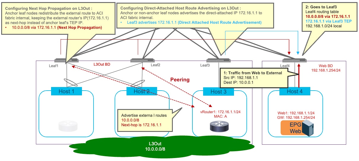
Figure 1. Example of Configuration to Avoid Suboptimal Traffic Flow with directly attached next-hop

To achieve the optimal traffic forwarding behavior shown above, the following configuration steps are required:

  1. Configuring Next Hop Propagation on L3Out: it enables the anchor leaf nodes to redistribute the external route with the next-hop IP address (that is the external device's IP address in this example) instead of the TEP address of the anchor leaf nodes. Therefore, the compute leaf nodes (Leaf4 in the example above) receives the external route with the external router’s IP address as the next-hop (10.0.0.0/8 via 172.16.1.1 in this specific example).

    More detail is available in the section Configuring Next Hop Propagation on L3Out.

  2. Defining a match rule for a route-map to match the external prefix for which next hop propagation should be enabled (10.0.0.0/8 in the example above).

  3. Defining a set rule for the same route-map to enable Next Hop Propagation for the external prefix.

  4. Creating the route-map for route control referencing the match rule and the set rule to enable next hop propagation for the external prefix.

  5. Applying the route-map to the L3Out. This is done in different ways, depending on the specific peering mechanism (BGP, OSPF or static routing):

    • If the external prefix (10.0.0.0/8 in the example above) is learned via BGP: selecting the route-map at the Route Control Profile on the BGP Peer Connectivity profile of the L3Out where the external routes are exchanged via BGP.

    • If the external prefix (10.0.0.0/8 in the example above) is learned via OSPF: selecting the route-map at the Route Profile for Interleak on the L3Out where the external routes are exchanged via OSPF.

    • If the external prefix (10.0.0.0/8 in the example above) is known via static routing configuration: selecting the route-map at the Route Profile for Redistribution on the L3Out where the static route is configured.

  6. Configuring Direct-Attached Host Route Advertising on L3Out: it enables the leaf nodes where the external routers are physically connected to redistribute the directly attached host routes to the Cisco Application Centric Infrastructure (ACI) fabric (172.16.1.1, 172.16.1.2, and 172.16.1.3 in the example above). See Configuring Direct-Attached Host Route Advertising on L3Out.

    • Creating a match rule for a route-map to specify the prefix of the L3Out’s SVIs subnet where the external router is directly connected (172.16.1.0/24 in the example above).

    • Creating the route-map for route control referencing the match rule to enable host route advertisement for the address of the router directly connected to the L3Out’s SVIs subnet.

    • Selecting the route-map at the Route Profile for Redistribution box on the L3Out where the external devices are connected.

If the next-hop for the external prefix is not directly attached to the L3Out’s SVIs subnet (for example when using a loopback on the external router as next-hop), additional configurations are required to enable an additional recursive lookup. Example of Configuration to Avoid Suboptimal Traffic Flow with recursive lookup illustrates an example. See Increasing the Local Maximum ECMP Paths in a BGP Address Family Context Policy.
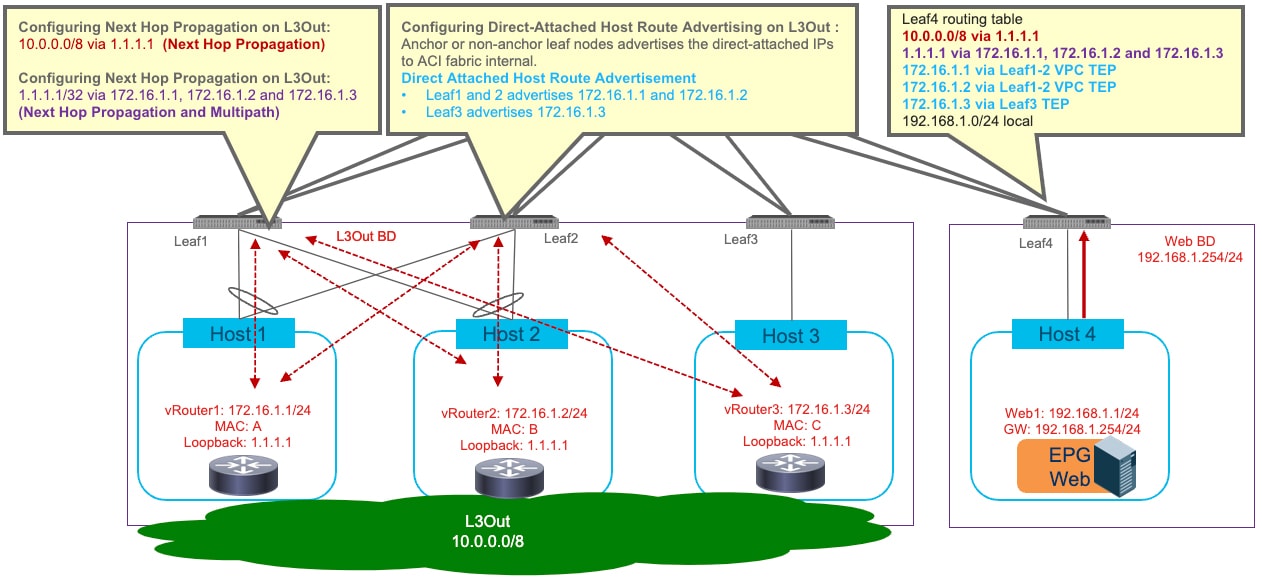
Figure 2. Example of Configuration to Avoid Suboptimal Traffic Flow with recursive lookup

The following configuration steps are required to enable this functionality:

  • Increase “Local Max ECMP” in BGP Address Family Context Policy: it enables the Cisco ACI fabric to increase Maximum Number of Paths when redistributing external routes from the anchor leaf nodes into the Fabric.

  • Configure Next Hop Propagation and Multipath on L3Out:

    • Creating a match rule for a route-map to specify the prefix to enable next hop propagation and multipath (loopback address 1.1.1.1/32 in the example above).

    • Creating a set rule for a route-map to enable Next Hop Propagation and Multipath.

    • Creating the route-map for route control referencing the match rule and the set rule to enable next hop propagation and multipath for the specific loopback IP prefix.

    • If the next-hop address (1.1.1.1 in the example above) is learned via OSPF: selecting the route-map at the Route Profile for Interleak box on the L3Out where the external routes are exchanged via OSPF.

    • If the next-hop address (1.1.1.1 in the example above) is learned via static route: selecting the route-map at the Route Profile for Redistribution box on the L3Out where the static route is configured.

The enablement of the functionality required to avoid sub optimal flow has the following considerations:

  • Cisco ACI release 5.0(1) or later is required.

  • If the next-hop for the external prefix is not directly attached to the L3Out’s SVIs subnet but require recursive lookup, Cisco ACI release 5.2(1) or later is required.

  • For Next Hop Propagation to work, the floating L3Out must be in a physical domain, not in a VMM domain.

  • If both OSPF and BGP need to redistribute routes into the ACI fabric, then you would have to configure OSPF and BGP under two different L3Outs. For example, the OSPF L3Out is required for the fabric to learn the next-hop loopback address, whereas the BGP L3Out is used to receive the external prefixes reachable via the next-hop address.

Configuring Next Hop Propagation on L3Out

This section explains how to create match and set rules for a route map, create a route map, configure route control profiles at a BGP peer connectivity profile, and configure a route profile for redistribution. The configuration steps described below refer the network topology and example shown in Example of Configuration to Avoid Suboptimal Traffic Flow with directly attached next-hop.

Before you begin

The following must be configured:

  • Floating L3Out with a physical domain (For Next Hop Propagation, the floating L3Out must be in a physical domain, not in a VMM domain.)

  • A BD, EPG, and a contract between the EPG and L3Out EPG

Procedure


Step 1

To create a match rule for a route map:

  1. From the navigation pane, go to Tenants > tenant_name > Policies > Protocol.

  2. Right-click on Match Rules and choose Create Match Rules for Route Map.

    The Create Match Rule dialog appears in the work pane.

  3. Enter a name in the Name field

  4. Locate the Match Prefix summary table and click the + to access the IP, Description, Aggregate, Greater Than Mask and Less Than Mask fields and enter the appropriate values.

    Note

     
    • The IP subnet should include the subnet that the external router advertises (in our example: 10.0.0.0/8).

    • Click the ? icon to open the help file and view a description of each field.

  5. When finished, click Submit.

Step 2

To create a set rule for a route map:

  1. From the navigation pane, go to Tenants > tenant_name > Policies > Protocol.

  2. Right-click on Set Rules and choose Create Set Rules for Route Map.

    The Create Set Rules for Route Map dialog appears in the work pane.

  3. Enter a name in the Name field.

  4. Click to place a check in the Next Hop Propagation checkbox.

  5. When finished, click Finish.

Step 3

To create a route map for route control:

  1. From the navigation pane, go to Tenants > tenant_name > Policies > Protocol.

  2. Right-click on Route Maps for Route Control and choose Create Route Maps for Route Control.

    The Create Route Maps for Route Control dialog appears in the work pane.

  3. Enter a name in the Name field.

  4. From the Contexts summary table in the Create Route Maps for Route Control dialog, click the + to access the Create Route Control Context dialog.

  5. From the Create Route Control Context dialog, click the Associated Match Rules + symbol to access the Rule Name field and choose the Match Rule created in Step 1.

  6. From the Create Route Control Context dialog, click the Set Rule drop-down menu and choose the Set Rule created in Step 2.

  7. When finished, click Submit.

If the next-hop for the external prefix is learned via BGP, go Step 4. If the next-hop for the external prefix is learned via OSPF, go Step 5. If the next-hop for the external prefix is learned via static route, go Step 6.

Step 4

To configure a route control profile in the BGP peer connectivity profile:

Note


The next hop propagation policy must be applied on the BGP peer connection policy in the L3Out for BGP.

  1. From the navigation pane, go to Tenants > tenant_name > Networking > L3Outs > L3Out_name > Logical Node Profiles > logical_node_profile_name > Logical Interface Profiles > logical_interface_profile_name > bgp_peer_connectivity_profile_name

    The BGP Peer Connectivity Profile properties appear in the work pane.

  2. From the Route Control Profile option in the BGP Peer Connectivity Profile window, click the +.

    The Name and Direction options are enabled.

  3. Click the Name drop-down menu to specify the route map created in Step 3.

  4. Click the Direction drop-down menu and choose Route Import Policy.

  5. When finished, click Update.

Step 5

To configure a Route Profile for Interleak on the L3Out where the OSPF route is learned.

  1. From the navigation pane, go to Tenants>tenant name>Networking >L3Outs>L3Out name.

  2. Click the Policy tab, then click the Main subtab.

  3. Locate the Route Profile for Interleak field and choose the route-map from step 3.

  4. Click Submit.

Step 6

To configure a Route Profile for Redistribution on the L3Out where the static route is configured.

  1. From the navigation pane, go to Tenants> tenant name>NetworkingL3Outs>L3Out name.

  2. Click the Policy tab, then click the Main subtab.

  3. From the Route Profile for Redistribution summary table, click the +. The Source and Route Map options are enabled.

  4. Click the Source drop-down menu to specify static.

  5. Click the Route Map drop-down menu to specify the route map from Step 3.

  6. When finished, click Update.


What to do next

Configuring Direct-Attached Host Route Advertising on L3Out

Configuring Direct-Attached Host Route Advertising on L3Out

This section explains how to create match and set rules for a route map, create a route map, configure route control profile for redistribution in order to advertise inside the fabric the specific IP addresses defined on the external routers for their connection to the SVIs L3Out network. The configuration steps described below refer to the network topology and example shown in Example of Configuration to Avoid Suboptimal Traffic Flow with directly attached next-hop.

Before you begin

The following must be configured:

  • Floating L3Out with a physical domain (For Direct-Attached Host route advertisement, the floating L3Out must be in a physical domain, not in a VMM domain.)

  • A BD, EPG, and a contract between the EPG and L3Out EPG

Procedure


Step 1

To create a match rule for a route map:

  1. From the navigation pane, go to Tenants > tenant_name > Policies > Protocol.

  2. Right-click on Match Rules and choose Create Match Rules for Route Map.

    The Create Match Rule dialog appears in the work pane.

  3. Enter a name in the Name field.

  4. Locate the Match Prefix summary table and click the + to access the IP, Description, Aggregate, Greater Than Mask and Less Than Mask fields and enter the appropriate values to configure the external router IPs. In our example it is IP address 172.16.1.1.

    Note


    Click the ? icon to open the help file and view a description of each field.

  5. When finished, click Submit.

Step 2

To create a route map for route control:

  1. From the navigation pane, go to Tenants > tenant_name > Policies > Protocol.

  2. Right-click on Route Maps for Route Control and choose Create Route Maps for Route Control.

    The Create Route Maps for Route Control dialog appears in the work pane.

  3. Enter a name in the Name field.

  4. From the Contexts summary table in the Create Route Maps for Route Control dialog, click the + to access the Create Route Control Context dialog.

  5. From the he Create Route Control Context dialog, click the Associated Match Rules + symbol to access the Rule Name field and choose the Match Rule created in Step 1.

  6. When finished, click Submit.

Step 3

To configure a route control profile for redistribution on an L3Out:

  1. From the navigation pane, go to Tenants > tenant_name > Networking > L3Outs > l3Out_name.

    The l3_outside_name window appears in the work pane.

  2. From the Route Profile for Redistribution summary table, click the +.

    The Source and Route Map options are enabled.

  3. Click the Source drop-down menu to specify attached-host

  4. Click the Route Map drop-down menu to specify the route-map from Step 2.

  5. When finished, click Update.


Increasing the Local Maximum ECMP Paths in a BGP Address Family Context Policy

This procedure configures the maximum number of paths for the redistributed routes in the Cisco Application Centric Infrastructure (ACI) fabric. Perform this procedure if the next-hop for the external prefix is not a directly attached host, but requires recursive lookup. The configuration steps described below refer to the network topology and example shown in Example of Configuration to Avoid Suboptimal Traffic Flow with recursive lookup.

Procedure


Step 1

Configure the maximum number of paths for the redistribution of routes in the Cisco ACI fabric. This is a necessary step before you can configure the Multipath field. See step 3 of Configuring Next Hop Propagation and Multipath on an L3Out.

Step 2

Navigate to Tenants > tenant name > Policies > Protocol> BGP > BGP Adress Family Context.

Step 3

In the Create BGP Address Family Context Policy dialog box, perform the following steps:

  1. In the Name field, enter a name for the policy.

    For example, enter redistr-mpath.

  2. Locate the Local Max ECMP field and enter the maximum number of paths (ECMP next hops) that should be selected when redistributing static or OSPF protocol routes learned on the border leaf switch into the MP-BGP fabric.

    The default value for this field is 0, which indicates that the Local Max ECMP setting is disabled. Enter a value greater than 0 to enable this setting. The valid range is from 1 to 16.

    Note


    Do not select the Enable Host Route Leak option in this scenario. This is not supported when configuring multi-protocol recursive next hop propagation.

  3. Click Submit after you have updated your entries.

Step 4

Navigate to Tenants > tenant name > Networking > VRFs > vrf name.

Step 5

Review the configuration details of the subject VRF.

Step 6

Locate the BGP Context Per Address Family field and, in the BGP Address Family Type area, select either IPv4 unicast address family or IPv6 unicast address family.

Step 7

Associate the BGP Address Family Context you created in the BGP Address Family Context drop-down list and associate it with the subject VRF.

Step 8

Click Submit.


Configuring Next Hop Propagation and Multipath on an L3Out

This procedure creates match and set rules for a route map, creates a route map, and configures route control profiles for the L3Out (using OSPF or static routing) where the next hop for the external prefix is learned (or reachable). This step is required if the next-hop for the external prefix is not directly attached host but requires recursive lookup. The configuration steps described below refer the network topology and example shown in Example of Configuration to Avoid Suboptimal Traffic Flow with recursive lookup.

Before you begin

Configure the following things:

  • Floating L3Out with a physical domain. For next hop propagation, the floating L3Out must be in a physical domain, not in a VMM domain.

  • If both OSPF and BGP must redistribute routes into the Cisco Application Centric Infrastructure (ACI) fabric, then configure OSPF and BGP under two different L3Outs.

  • A BD, EPG, and a contract between the EPG and the L3Out EPG for the external prefixes.

Procedure


Step 1

To create a match rule for a route map:

  1. From the navigation pane, go to Tenants >tenant_name > Policies > Protocol.

  2. Right-click Match Rules and choose Create Match Rules for Route Map.

    The Create Match Rule dialog appears in the work pane.

  3. Enter a name in the Name field.

  4. In the Match Prefix summary table and click + to access the IP, Description, Aggregate, Greater Than Mask and Less Than Mask fields and enter values to match the external router's loopback IP address that is utilized as next-hop to reach the external prefixes.

  5. Click Submit.

Step 2

To create a set rule for a route map:

  1. From the navigation pane, go to Tenants >tenant_name > Policies > Protocol.

  2. Right-click Set Rules and choose Create Set Rules for Route Map.

    The Create Set Rules for Route Map dialog appears in the work pane.

  3. Enter a name in the Name field.

  4. Click to place a check in the Next Hop Propagation and Multipath checkbox.

    • Next Hop Propagation: Select this option to propagate the next hop address advertised by the external BGP peer into the fabric. If you do not enable this option, the tunnel endpoint (TEP) of the border leaf switch is used as the next hop on the other leaf switches.

    • Multipath: Select this option to specify if multiple paths (ECMP next hops) need to be picked for redistribution for a particular route when performing a next hop unchanged redistribution. The number of paths used is based on the value that you entered in the Local Max ECMP field configured at “Increase Local Max ECMP in BGP Address Family Context Policy”.

  5. When finished, click Finish.

Step 3

To create a route map for route control:

  1. From the navigation pane, go to Tenants >tenant_name > Policies > Protocol.

  2. Right-click on Route Maps for Route Control and choose Create Route Maps for Route Control.

    The Create Route Map for Route Control dialog appears in the work pane.

  3. Enter a name in the Name field.

  4. From the Contexts summary table in the Create Route Map for Route Control dialog, click + to access the Create Route Control Context dialog.

  5. From the Create Route Control Context dialog, click the Associate Map Rules+ symbol to access the Rule Name field and choose the Match Rule created in Step 1.

  6. From the Create Route Control Context dialog, click the Set Rule drop-down menu and choose the Set Rule created in Step 2.

  7. When finished, click Submit.

If the next hop for the external prefix is learned from OSPF, go to Step 4. If the next hop for the external prefix is learned from a static route, go to Step 5.

Step 4

To configure a route profile for interleak on the L3Out where the OSPF route is learned:

  1. From the Navigation pane, choose Tenants >tenant_name > Networking > L3Outs > L3Out name.

  2. Click the Policy tab, then click the Main subtab.

  3. Locate the Route Profile for Interleak field and choose the route map from Step 3.

  4. Click Submit.

Step 5

To configure a route profile for redistribution on the L3Out where the static route is configured:

  1. From the Navigation pane, choose Tenants >tenant_name > Networking > L3Outs > L3Out name.

  2. Click the Policy tab, then click the Main subtab.

  3. From the Route Profile for Redistribution summary table, click the +.

    The Source and Route Map options are enabled.

  4. Click the Source drop-down menu to specify static.

  5. Click the Route Map drop-down menu to specify the route map from Step 3.

  6. When finished, click Update.


Verifying the L3Out Configuration

After you configure the floating Layer 3 outside network connection (L3Out), verify the creation of the port group in the VMware vCenter and the leaf node configuration on the Cisco Application Policy Infrastructure Controller (APIC).

Verify the Floating L3Out Port Group in the VMware vCenter

Verify that the port group has been generated for the Layer 3 outside connection (L3Out) in the VMware vCenter if it is a floating L3Out with a VMM domain.

Before you begin

You must have configured a floating L3Out with a VMM domain.

Procedure


Step 1

Log into the VMware vCenter.

Step 2

Navigate to data center and the VMware VDS, and then expand the VMware VDS to view the port-groups.

Step 3

In the left navigation pane, find the port group that has been generated for the L3Out.

The port group has a name in the following format: Tenant_name|L3Out_name|VLAN-number.

For example, if your tenant name is Floating, your L3Out name is ExtConnect1, and the VLAN number is 205, the port group name is Floating|ExtConnect1|205.

Step 4

Under the Summary tab, ensure that the VLAN ID is the same as the last number of the VLAN range and that the information in the Distributed Port Group Details is correct.


What to do next

Verify Floating L3Out on the Leaf Nodes Using the Cisco APIC GUI

Verify Floating L3Out on the Leaf Nodes Using the Cisco APIC GUI

Verify that the leaf nodes have the correct IP addresses.

Before you begin

You must have configured a floating L3Out.

Procedure


Step 1

Log in to Cisco Application Policy Infrastructure Controller (APIC).

Step 2

Go to Fabric > Inventory.

Step 3

In the Inventory navigation pane, expand the pod, the anchor_leaf_node, the Interfaces folder, and the External SVI Interfaces folder.

Step 4

Click the interface for the floating L3Out.

The name should have the format vlan-VLAN_ID. For example, if the VLAN that you configured for the Layer 3 and VMM domains is 205, the interface is named vlan-205.

Step 5

In the Routed Vlan Interface central work pane, ensure that the IP address is the primary IP address and that the interface is up.

Step 6

Note the Interface VLAN ID, which belongs to the actual VLAN on the leaf switch.

The VLAN ID appears at the top of and in the Properties list of the central work pane.

Step 7

In the In the Inventory navigation pane, under the Interfaces folder, choose the Physical Interfaces folder.

Step 8

In the Interfaces central work pane, choose the Physical Interfaces tab.

Step 9

Choose your physical interfaces—for example, eth 1/8 and eth 1/9—expand the Oper Vlans column, and ensure that the VLAN ID that you noted is in the list.

Step 10

Repeat this procedure for the non-anchor leaf nodes, choosing the non-anchor leaf node in step 3.