Switch Fabric Overview
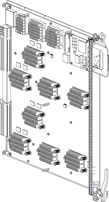
The switch fabric is the core of the Cisco CRS routing system. The Cisco CRS routing system fabric is implemented through multiple redundant switch fabric cards (SFCs) installed in the chassis. The switch fabric uses a cell-switched, buffered, three-stage Benes switch fabric architecture. The switch fabric receives user data from a modular services card (MSC) or Forwarding Processing card (FP) and performs the switching necessary to route the data to the appropriate egress MSC or FP.
The switch fabric is divided into eight planes (plane 0 to plane 7) that are used to evenly distribute traffic across the switch fabric. Each switch fabric plane is independent and not synchronized with one another. Each cell traverses the switch fabric using a single switch fabric plane (cells are not bit-sliced across the switch fabric).
When operating as a single-shelf (standalone) system, the line card chassis (LCC) uses one of the following SFCs:
- CRS-16-FC/S (40G)
- CRS-16-FC140/S (140G)
- CRS-16-FC400/S (200G)
Each fabric card implements all three stages of the switch fabric. Note the following:
- The CRS-16-FC140/S fabric is able to operate in both 40G mode and 140G mode to allow interconnection between 20G, 40G, or 140G MSCs and FPs.
- The CRS-16-FC400/S fabric is able to operate in 40G, 140G and 200G mode to allow interconnection between the 20G, 40G, 140G, or 200G MSCs and FPs.
 Note |
The LCC supports either 40G fabric cards (FC/S cards), 140G fabric cards (FC-140/S cards), or 400G fabric cards (FC-400/S cards in 200G mode). An LCC with a mix of 40G, 140G, and 400G fabric cards is not a supported mode of operation. Such a mode is temporarily allowed only during the upgrade process. |
When operating as part of a multishelf system for the Cisco CRS-1,Cisco CRS-3 or CRS-X, the chassis accepts either the CRS-16-FC/M (40G), CRS-16-FC140/M (140G), or CRS-16-FC400/M (200G) SFC. In a multishelf system, the SFC cards installed in the LCCs perform the S1 stage and S3 stage functions, while the S2 stage of the switch fabric is provided by S2 switch fabric cards in the fabric card chassis (FCC). Like the CRS-16-FC140/S fabric, the CRS-16-FC140/M fabric operates in 40G and 140G mode
.With the CRS-16-FC140/M S2 fabric in the FCC, the LCCs in a multishelf system can be a mixture of 40G fabric LCCs and 140G fabric LCCs; in this case, only those LCCs requiring 140G support would need to be upgraded. Also, like the CRS-16-FC400/S fabric, the CRS-16-FC400/M fabric operates in 40G, 140G, and 200G mode.
With the CRS-16-FC400/M S2 fabric in the FCC, the LCCs in a multishelf system can be a mixture of 40G fabric LCCs, 140G fabric LCCs, and 200G LCCs; in this case, only those LCCs requiring 200G support would need to be upgraded. See the next section for details about the stages of the switch fabric.
The following figure shows the basic path of IP data packets through the Cisco CRS routing system switch fabric. Note that the figure shows a single-shelf system, in which all three stages of the switch fabric are provided by switch fabric cards in the line card chassis. In a multishelf system, Stage 2 of the switch fabric is provided by S2 fabric cards in the fabric card chassis.

Ingress data packets are received at a physical interface on a PLIM and transferred to the associated MSC, where the packets are segmented into cells for efficient switching by the switch fabric hardware. Each MSC has multiple connections to each switch fabric plane, which it uses to distribute cells to each fabric plane. On egress, cells are reassembled into data packets before being transmitted by the egress MSC.
 Note |
The cell structure used in the Cisco CRS routing system switch fabric is a Cisco-specific cell structure and is not related to Asynchronous Transfer Mode (ATM) cells. |


 Feedback