Route Processor Overview
The route processor (RP) card performs the route processing in the Cisco CRS routing system and distributes forwarding tables to the MSCs. The RP provides a control path to each MSC, performs system-monitoring functions and contains hard disks for system and error logging.
Although each line card chassis contains two RP cards, only one RP is active at a time. The other RP operates in standby mode, ready to assume control if the active RP fails. See Route Processor Active and Standby Arbitration for information on how the system determines which RP is active and which is standby. As of Cisco IOS XR release 3.3.0, the RP and RP-B in tandem for active and standby modes (or vice versa) are supported on the one routing system chassis.
The RP card is also the system controller for the Cisco CRS routing system. See Control Plane for more information about system controller functions.) System controller functionality varies between single-shelf and multishelf systems:
- In a single-shelf (standalone) system, the active RP is the system controller for the routing system.
- In a multishelf system, one of the RPs from among all of the line card chassis is selected to be the designated system controller (DSC) for the routing system. See Cisco CRS Carrier Routing System Multishelf System Description for more information about the selection process.)
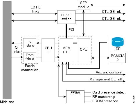
The following figure is a simple block diagram of an RP card. The dotted lines indicate distinct RP modules, such as the CPU and memory controller (MEM CTL), and the “to fabric” and “from fabric” sections.

The main components of the RP card are listed here and described in the following sections:
- A dual-CPU symmetric multiprocessor (SMP) performs route processing. The CPU also serves as the MSC service processor (SP), and monitors the RP temperature, voltages, power supply margining (during factory test), and ID EEPROM.
- Two small form-factor pluggable (SFP) modules provide external Gigabit Ethernet (GE) connections. In a multishelf system, these modules connect to two external Catalyst 6509 systems that interconnect all line card and fabric chassis together to form a control network. The Cat6509 systems are not used in the single-shelf system.
- A third Ethernet port for 10/100/1000 Ethernet copper provides connectivity to network management systems.
- Internal 100 Mbps Fast Ethernet (FE) midplane connections connect each MSC in the chassis to both RPs. These FE connections are traces in the midplane. There are also FE connections to the fans, blowers and power supplies. These connections all form part of the control plane.
- An IDE hard disk is used to gather debugging information, such as core dumps from the RP or MSCs. See IDE Hard Drive for more information.
- PCMCIA flash slots provide support for two PCMCIA flash subsystems that each provide 2GB or 4GB of flash storage. One of the PCMCIA flash subsystems is accessible externally and removable; the other subsystem is fixed to the RP and is not removable. See PCMCIA Flash Slots.
As shown in the above figure, the RP mates with the Cisco CRS 16-slot line card chassis midplane. The RP connects to the switch fabric through two fabric interface modules (from fabric and to fabric) that are similar to the fabric interface of the MSC. See MSC To Fabric Section and Queuing).
- The from fabric section (which is part of the RP receive path) queues the data from the switch fabric and reorders and reassembles the cells into packets before queuing them for slow-path processing.
- The to fabric module (which is part of the RP transmit path) queues the packets and segments them into cells before transmitting them to the switch fabric.
IDE Hard Drive
The RP hard drive (see the following figure) is an IDE hard disk used to gather debugging information, such as core dumps from the RP or MSCs. The hard drive is typically powered down and activated only when there is a need to store data. A hard disk is always provided as part of the RP, but may be removed from the board if necessary (under the direction of Cisco technical support).

|
1 |
Hard drive door |
 Note |
Physically, the hard drive is a hot-pluggable PC board and sled-mounted drive with a connector interface that seats into an RP card. In general, removal and replacement of this drive is not required. |
PCMCIA Flash Slots
The RP card supports two PCMCIA flash cards that each provide up to 2GB or 4GB of flash storage. One of the PCMCIA flash subsystems is accessible externally and removable, and allows you to transfer images and configurations by plugging in a PCMCIA flash card. The other flash subsystem is fixed to the RP and is not removable, and is for permanent storage of configurations and images. The following figure shows the location of the externally accessible PCMCIA slot on the RP card front panel.
 Note |
Only the original route processor (RP) card uses a PCMCIA card. The performance route processor (PRP) card has a USB connector for using a flash drive. |

|
1 |
PCMCIA flip-up door |
CONSOLE and AUX Ports
The CONSOLE and AUX ports are RJ-45 serial connectors that have the following pinouts:
- Pin 1—Request to send (RTS)
- Pin 2—Data terminal ready (DTR)
- Pin 3—Transmit data (TxD)
- Pin 4—Ground (Gnd)
- Pin 5—Ground (Gnd)
- Pin 6—Receive data (RxD)
- Pin 7—Carrier detect (CD)
- Pin 8—Clear to send (CTS)


 Feedback