IRM-1100-4A2T Overview
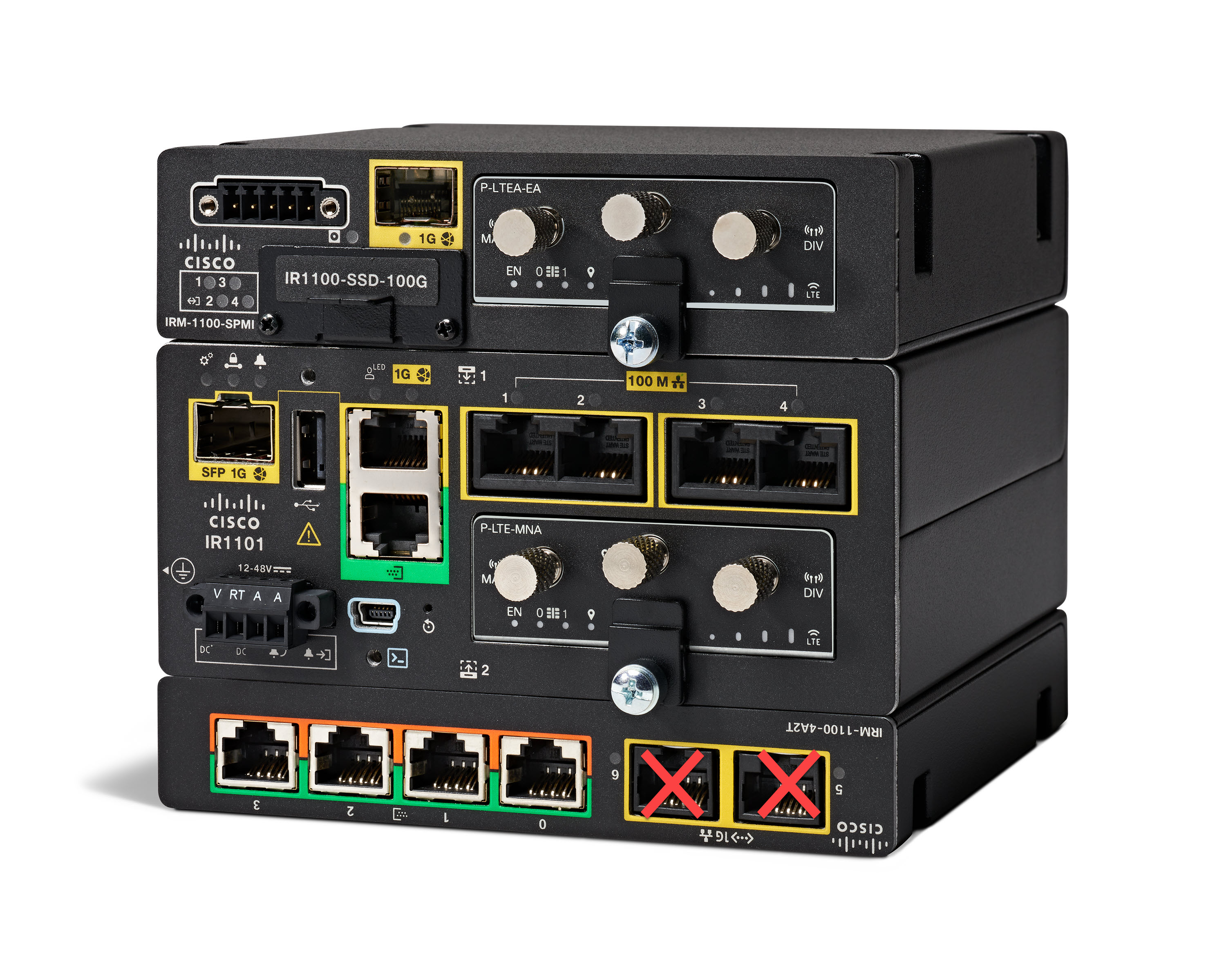
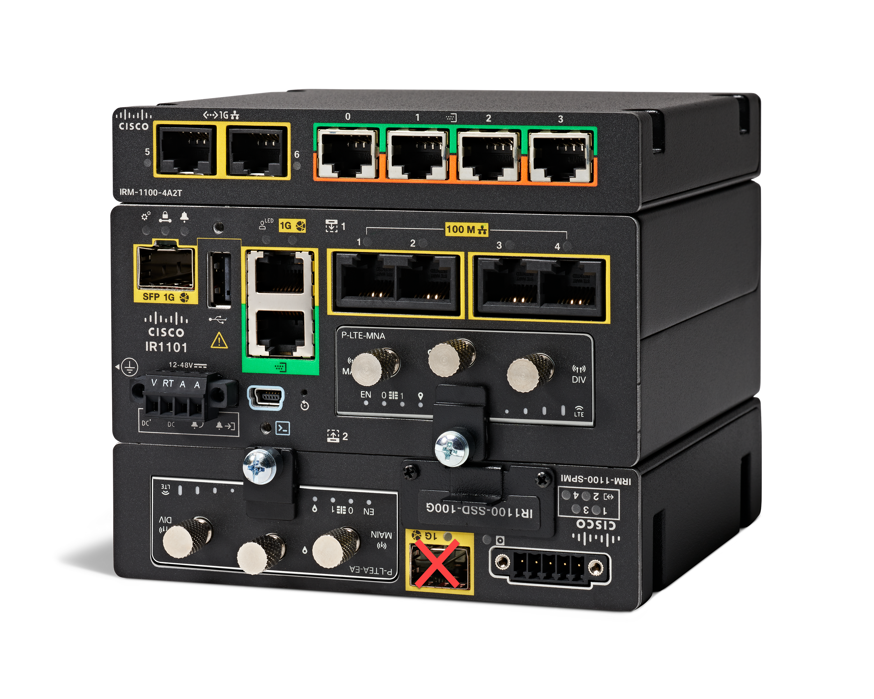
The IRM-1100-4A2T is an expansion module that can be attached to the IR1101. It offers an additional four asynchronous serial ports and two Ethernet interfaces to the IR1101. The following graphic shows the IRM-1100-4A2T.

The IRM-1100-4A2T Ethernet interfaces are Layer 2 RJ45 10/100/1000 Mbps ports.
The IRM-1100-4A2T serial ports are RJ45 combo ports (RS232/RS485/RS422).
The IR1101 has two sides that expansion modules mount to. The top is called the Expansion side, and the bottom is called the Compute side. If the additional module is connected to the top, then it is referenced as the Expansion Module (EM) side. If the additional module is connected on the bottom, then it is referenced as the Compute Module (CM) side. Functionality differs depending on which side the expansion module is attached to, and how many and type of expansion modules are in use.
 Note |
For more information, see the Installing the IRM-1100-4A2T Expansion Module section. |
The IRM-1100-4A2T can be managed from the following tools:
-
Cisco DNA Center
-
WebUI
Router Switch Path
The switch path that is detected on the platform, is based on the type of additional module connected on the Expansion module (EM) side. Refer to the following table:
|
Additional Module |
Switch Path |
|---|---|
|
No Module Connected |
IR1101-ES-5 |
|
IRM-1100-SPMI |
IR1101-ES-6S |
|
IRM-IR1100-4A2T |
IR1101-ES-7G |
 Note |
When an IRM-IR1100-4A2T is connected on both sides of the IR1101-K9, there is a maximum of nine Async interfaces which can be enumerated. The switch path for the IR1101-K9 will be IR1101-ES-7G. |
Serial Port Pinouts and Characteristics
The serial ports are intended as a DCE port, capable of both RS232 and RS485. RS485 can support full or half duplex.
The RJ45 pinouts are shown in the following figure and table:

| RS232 | RS485 Full Duplex | RS485 Half Duplex | ||||||
|---|---|---|---|---|---|---|---|---|
|
Pin # |
Signal Description |
Abbr. |
S0 (DTE) |
S1 (DCE) |
Signal |
DIR |
Signal |
Direction |
|
1 |
DCE ready. Used as DSR in Cisco IOS. |
DSR/RI |
Input |
Output |
TX- |
Output |
TX/RX+ |
<-> |
|
2 |
Received Line Signal Detector |
DCD |
Input |
Output |
TX+ |
Output |
TX/RX- |
<-> |
|
3 |
DTE Ready |
DTR |
Output |
Input |
RX- |
Input |
— |
— |
|
4 |
Signal Ground |
COM |
— |
— |
COM |
— |
COM |
— |
|
5 |
Received Data |
RxD |
Input |
Output |
— |
— |
— |
— |
|
6 |
Transmitted Data |
TxD |
Output |
Input |
RX+ |
Input |
— |
— |
|
7 |
Clear To Send |
CTS |
Input |
Output |
— |
— |
— |
— |
|
8 |
Request To Send |
RTS |
Output |
Input |
— |
— |
— |
— |


 Feedback