Enterprise Firewall with Application Awareness

Cisco’s Enterprise Firewall with Application Awareness feature uses a flexible and easily understood zone-based model for traffic inspection, compared to the older interface-based model.

Overview of Enterprise Firewall with Application Awareness

The Enterprise Firewall with Application Awareness uses a flexible and easily understood zone-based model for traffic inspection, compared to the older interface-based model.

A firewall policy is a type of localized security policy that allows stateful inspection of TCP, UDP, and ICMP data traffic flows. Traffic flows that originate in a given zone are allowed to proceed to another zone based on the policy between the two zones. A zone is a grouping of one or more VPNs. Grouping VPNs into zones allows you to establish security boundaries in your overlay network so that you can control all data traffic that passes between zones.

Zone configuration consists of the following components:

  • Source zone—A grouping of VPNs where the data traffic flows originate. A VPN can be part of only one zone.

  • Destination zone—A grouping of VPNs where the data traffic flows terminate. A VPN can be part of only one zone.

  • Firewall policy—A security policy, similar to a localized security policy, that defines the conditions that the data traffic flow from the source zone must match to allow the flow to continue to the destination zone. Firewall policies can match IP prefixes, IP ports, the protocols TCP, UDP, and ICMP, and applications. Matching flows for prefixes, ports, and protocols can be accepted or dropped, and the packet headers can be logged. Nonmatching flows are dropped by default. Matching applications are denied.

  • Zone pair—A container that associates a source zone with a destination zone and that applies a firewall policy to the traffic that flows between the two zones.

Matching flows that are accepted can be processed in two different ways:

  • Inspect—The packet's header can be inspected to determine its source address and port. When a session is inspected, you do not need to create a service-policy that matches the return traffic.

  • Pass—Allow the packet to pass to the destination zone without inspecting the packet's header at all. When a flow is passed, no sessions are created. For such a flow, you must create a service-policy that will match and pass the return traffic.

The following figure shows a simple scenario in which three VPNs are configured on a router. One of the VPNs, VPN 3, has shared resources that you want to restrict access to. These resources could be printers or confidential customer data. For the remaining two VPNs in this scenario, only users in one of them, VPN 1, are allowed to access the resources in VPN 3, while users in VPN 2 are denied access to these resources. In this scenario, we want data traffic to flow from VPN 1 to VPN 3, but we do not want traffic to flow in the other direction, from VPN 3 to VPN 1.
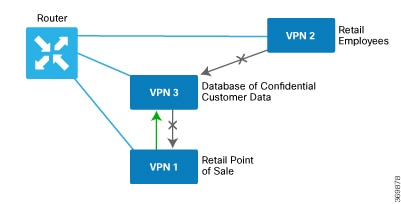

Note

From Cisco IOS XE SD-WAN Release 16.12.2r and onwards, vManage does not show ZBFW statistics for classes that are without any value. If the statistics are "zero" for any of the configured sequences, these are not shown on the device dashboard for zone-based firewall.


Application Firewall

The Application Firewall blocks traffic based on applications or application-family. This application-aware firewall feature provides the following benefits:

  • Application visibility and granular control

  • Classification of 1400+ layer 7 applications

  • Blocks traffic by application or application-family

You can create lists of individual applications or application families. A sequence that contains a specified application or application family list can be inspected. This inspect action is a Layer 4 action. Matching applications are blocked/denied.

The router provides Application Layer Gateway (ALG) FTP support with Network Address Translation – Direct Internet Access (NAT-DIA), Service NAT, and Enterprise Firewall. Service NAT support is added for FTP ALG on the client and not on the FTP Server.


Note

The Application Firewall is valid only for Cisco IOS XE SD-WAN devices.


Restrictions for Enterprise Firewall

You can configure up to 200 rules for firewalls in Cisco vManage.

Configure Firewall Policies

In vManage NMS, you configure firewall policies from the Configuration > Security screen, using a policy configuration wizard. In the CLI, you configure these firewalls on the XE SD-WAN Router.

Configuration Components

For firewall policies, you configure zones and a policy to apply to those zones.

Each zone consists of one of more VPNs in the overlay network. You define a source zone, which identifies the VPNs from which data traffic originates, and a destination zone, which identifies the VPNs to which the traffic is being sent.

The firewall policy consists of a series of numbered (ordered) sequences of match–action pairs that are evaluated in order, from lowest sequence number to highest sequence number. When a data packet matches the match conditions, the associated action or actions are taken and policy evaluation on that packet stops. Keep this process in mind as you design your policies to ensure that the desired actions are taken on the items subject to policy.

If a packet matches no parameters in any of the policy sequences, you define a default action to be taken on the packet.

The following figure illustrates the configuration components for firewall policies:

To create an application firewall policy, you include the following components in the configuration for a XE SD-WAN Router:

Component

Description

vManage Configuration

CLI Configuration Command

Lists

Groupings of related items that you reference in the match portion of the firewall policy configuration.

Configuration ► Security ► Custom Options ► Lists ► Application

Configuration ► Security ► Custom Options ► Lists ► Zones 

policy lists

Firewall policy

Container for a firewall policy.

Configuration ► Security ► Add Security Policy ► <Scenario> ► Add Firewall Policy

policy zone-based-policy

Numbered sequences of match–action pairs

Sequences establish the order in which the policy components are applied.

Configuration ► Security ► Add Security Policy ► <Scenario> ► Add Firewall Policy ► Sequence Rule

policy zone-based-policy sequence

Application Match parameters

Conditions that packets must match to be considered for a security policy.

Configuration ► Security ► Add Security Policy ► <Scenario> ► Add Firewall Policy ► Sequence Rule ► Match ► Application/Application Family List

policy zone-based-policy sequence match app-list

Actions

For a sequence that contains an application or application family list, packets can be inspected. Matching applications are blocked/denied.

Configuration ► Security ► Add Security Policy ► <Scenario> ► Add Firewall Policy ► Sequence Rule ► Actions ►Inspect

policy zone-based-policy sequence action inspect

Default action

Action to take if a packet matches none of the match parameters in any of the sequences. By default, non matching packets are dropped.

Configuration ► Security ► Add Security Policy ► <Scenario> ► Add Firewall Policy ► Sequence Rule ► Actions

policy zone-based-policy default-action drop

Apply firewall policy to a zone pair

For a firewall policy to take effect, you include it in the definition of a zone pair.

Configuration ► Security ► Add Security Policy ►<Scenario> ►Apply Policy

policy zone-pair

General vManage Configuration Procedure

To configure firewall policies, use the vManage policy configuration wizard. The wizard is a UI policy builder that lets you configure policy components:

  • Create Lists—Create lists that group together related items and that you call in the match condition of a firewall policy.

  • Firewall Policy—Define the match and action conditions of the firewall policy.

  • Apply Configuration—Define zone pairs.

You must configure all these components to create a firewall policy. If you are modifying an existing firewall, you can skip a component by clicking the Next button at the bottom of the screen. To return to a component, click the Back button at the bottom of the screen.

Configuration Components

UTD security policy components consist of the following:

  • Intrusion prevention policy—Protects against malicious attacks on data traffic by using signature sets and inspection mode. Intrusion detection passes all packets flowing between service-side and transport-side (WAN or internet) interfaces, and between VLANs, through an intrusion detection engine, generating alerts for traffic that is identified as malicious, and logging these alerts via syslog. Intrusion prevention blocks traffic that is identified as malicious.

  • URL filtering policy—Allows and disallows access to specific URLs and webpage categories. URL filtering allows you to control access to Internet websites by permitting or denying access to specific websites based on lists, categories, and reputations. For example, when a client sends a HTTP or HTTPS request, the router inspects the traffic. If, for example, the request matches the blocked list, a custom blocked page is displayed or it is redirected to a different URL. If, for example, the HTTP or HTTPS request matches the allowed list, the traffic is allowed without further URL filtering inspection.

Create or Modify Lists

To create an application firewall policy, you include the following components in the configuration for a XE SD-WAN Router:

Component

Description

vManage Configuration

CLI Configuration Command

Lists

Groupings of related items that you reference in the match portion of the firewall policy configuration.

Configuration ► Security ► Custom Options ► Lists ► Application

Configuration ► Security ► Custom Options ► Lists ► Zones 

policy lists

Firewall policy

Container for a firewall policy.

Configuration ► Security ► Add Security Policy ► <Scenario> ► Add Firewall Policy

policy zone-based-policy

Numbered sequences of match–action pairs

Sequences establish the order in which the policy components are applied.

Configuration ► Security ► Add Security Policy ► <Scenario> ► Add Firewall Policy ► Sequence Rule

policy zone-based-policy sequence

Application Match parameters

Conditions that packets must match to be considered for a security policy.

Configuration ► Security ► Add Security Policy ► <Scenario> ► Add Firewall Policy ► Sequence Rule ► Match ► Application/Application Family List

policy zone-based-policy sequence match app-list

Actions

For a sequence that contains an application or application family list, packets can be inspected. Matching applications are blocked/denied.

Configuration ► Security ► Add Security Policy ► <Scenario> ► Add Firewall Policy ► Sequence Rule ► Actions ►Inspect

policy zone-based-policy sequence action inspect

Default action

Action to take if a packet matches none of the match parameters in any of the sequences. By default, non matching packets are dropped.

Configuration ► Security ► Add Security Policy ► <Scenario> ► Add Firewall Policy ► Sequence Rule ► Actions

policy zone-based-policy default-action drop

Apply firewall policy to a zone pair

For a firewall policy to take effect, you include it in the definition of a zone pair.

Configuration ► Security ► Add Security Policy ►<Scenario> ►Apply Policy

policy zone-pair

Create Lists

You create lists that group together related items and that you call in the match condition of a firewall policy.

To create lists:

  1. In vManage NMS, select the Configure > Security screen.

  2. In the Title bar, click the Custom Options drop-down.

  3. Select Lists. The Define Lists screen displays.

  4. Select the list type to create. The following table describes the lists you can create for firewall policies.

List Type

Procedure

Application

  1. In the left pane, click Application.

  2. Click New Application List.

  3. Enter a name for the list.

  4. Select individual applications or application families.

  5. Click Add.

Data Prefix

  1. In the left pane, click Data Prefix.

  2. Click New Data Prefix List.

  3. Enter a name for the list.

  4. Enter one or more IP prefixes.

  5. Click Add.

Zones

  1. In the left pane, click Zones.

  2. Click New Zone List.

  3. Enter a name for the zone list.

  4. In the Add VPN field, enter the number or numbers of the VPN in the zone. Separate numbers with commas.

  5. Click Add.

You can edit, copy, or delete an existing list, click the Edit, Copy, or Trash Bin icon in the Action column.

Use the Policy Configuration Wizard

This article provides procedures for configuring firewall policies on XE SD-WAN Routers. You provision firewall policies to direct traffic between two zones, which are referred to as a source zone and a destination zone. Each zone consists of one or more VPNs in the overlay network.

In vManage NMS, you configure firewall policies from the Configuration > Security screen, using a policy configuration wizard. In the CLI, you configure these firewalls on the XE SD-WAN Router.

Start the Policy Configuration Wizard

To start the policy configuration wizard:

  1. In vManage NMS, select the Configure > Security screen.

  2. Click Add Security Policy.

The Add Security Policy configuration wizard opens, and various use-case scenarios display.

Select a Use-Case Scenario

In Add Security Policy, select a policy based on use-case scenarios, or build your own custom policy.

  1. Select a security policy use-case scenario. The following table describes the use-case scenarios.

    • Compliance – Applies application firewall and intrusion prevention.

    • Guest Access – Applies application firewall and URL filtering.

    • Direct Cloud Access – Applies application firewall, URL filtering, and DNS Umbrella security.

    • Direct Internet Access – Applies application firewall, intrusion prevention, URL filtering, and DNS Umbrella security.

    • Custom – Build your own security policy by combining various security policy blocks.

  2. Click Proceed to add a firewall policy in the wizard.

Configure Firewall Policy

  1. Click the Add Firewall Policy drop-down.

  2. To create a new firewall policy

    1. Select Create New.

    2. Enter a name and description for the policy.

    3. Go to Step 4.

  3. To import an existing zone-based firewall policy:

    1. Select Copy from Existing. The Copy from Existing Firewall Policy dialog box appears.

    2. From the Policy drop-down, select the policy to copy.

    3. In the Policy Name field, accept the default name (policy_name_copy) or enter a new name.

    4. In the Policy Description field, enter a description.

    5. Click Copy.

    6. To modify the policy, click the More Actions icon to at the far right of the policy and select Edit. Go to Step 4.

    Otherwise, click Next to move to the next security block in the configuration wizard.

  4. In the left pane, click Sequence Rule to create a single sequence in the firewall policy. The Match tab is selected by default.

  5. Click a match condition:

    • Source Data Prefix

    • Source Port

    • Destination Data Prefix

    • Destination Port

    • Protocol

    • Application/Application Family List

  6. Enter the values for the match condition. 


    Note

    If you selected an Application or Application Family List, you must select at least one other match condition.


  7. Click the Actions tab.

  8. Enter the action or actions to take if the traffic matches.


    Note

    If a match condition contains an Application or Application Family List, the action must be Inspect. This inspect action is a Layer 4 action. The action for a specific application is block/deny.


  9. Click Save Match and Actions to save match-action pair.

  10. Repeat Steps 4 through 9 to add match–action pairs to the firewall policy.

  11. To rearrange match–action pairs in the policy, drag them to the desired position.

  12. To edit, copy, or delete a sequence rule, in the right pane, click the edit, copy, or delete icon to the right of the sequence rule.

  13. If no packets match any of the policy sequence rules, the default action is to drop the packets. To change the default action:

    1. Click the Pencil icon.

    2. Change the default action to Inspect or Pass.

    3. Click Save Match and Actions.

Apply Policy to a Zone Pair

Table 1. Feature History

Feature Name

Release Information

Description

Self Zone Policy for Zone-Based Firewalls

Cisco IOS XE SD-WAN Release 16.12.1b

This feature can help define policies to impose rules on incoming and outgoing traffic.

  1. At the top of the page, click Apply Zone-Pairs.

  2. In the Source Zone field, select the zone that is the source of the data packets.

  3. In the Destination Zone field, select the zone that is the destination of the data packets.


    Note

    You can select the same zone for both source and destination. However, if the packet's source and destination use the same physical interface (resulting in U-turn traffic), a firewall session is not created and traffic passes.


  4. Click the plus (+) icon to add zone pairs.

  5. Click Save.

  6. At the bottom of the page, click Save Firewall Policy to save the policy.

  7. To edit or delete a firewall policy, in the right pane, click the More Actions icon to the far right of the policy and select the desired option.

  8. Click Next to configure the next security block in the wizard.

    • Intrusion Prevention

    • URL Filtering

    • DNS Security

Policy Summary

  1. Enter a name for the security policy. This field is mandatory and can contain only uppercase and lowercase letters, the digits 0 through 9, hyphens (–), and underscores (_). It cannot contain spaces or any other characters.

  2. Enter a description for the security policy. This field is mandatory.

  3. (Optional) For Cisco IOS XE SD-WAN Release 16.12.x and onwards, to configure high-speed logging (HSL), enter the following details of the Netflow server that will listen for the Netflow event logs:


    Note

    For more information on HSL, see Firewall High-Speed Logging Overview.


    1. In the VPN field, enter the VPN that the server is in.

    2. In the Server IP field, enter the IP address of the server.

    3. In the Port field, enter the port on which the server is listening.

  4. If you configured an application firewall policy, uncheck the “Bypass firewall policy and allow all Internet traffic to/from VPN 0” check box in the Additional Security Policy Settings area.

  5. (Optional) To configure an audit trail, enable the Audit Trail option. This option is only applicable for rules with an Inspect action.

  6. Click Save Policy to save the security policy.

Apply Policy to a Zone Pair

Table 2. Feature History

Feature Name

Release Information

Description

Self Zone Policy for Zone-Based Firewalls

Cisco IOS XE SD-WAN Release 16.12.1b

This feature allows you to define firewall policies for incoming and outgoing traffic between a self zone of an edge router and another zone. When a self zone is configured with another zone, the traffic in this zone pair is filtered as per the applied firewall policy.

Note

For IPSEC overlay tunnels in Cisco SD-WAN, if a self zone is selected as a zone pair, firewall sessions are created for SD-WAN overlay BFD packets if inspect action is configured for UDP.

However, for GRE overlay tunnels, if you chose a self zone as a zone pair with the inspect action of protocol 47, firewall sessions are created only for TCP, UDP, ICMP packets; but not BFD packets.


Warning

Control connections may be impacted when you configure drop action from self-zone to VPN0 and vice versa. This applies for DTLS/TLS, BFD packets, and IPsec overlay tunnel.


To apply policy to a zone pair:

  1. Create security policy using Cisco vManage. See

    https://www.cisco.com/c/en/us/td/docs/routers/sdwan/configuration/security/ios-xe-17/security-book-xe/m-firewall-17.html#c-use-the-policy-configuration-wizard-17

  2. At the top of the page, click Apply Zone-Pairs.

  3. In the Source Zone field, choose the zone that is the source of the data packets.

  4. In the Destination Zone field, choose the zone that is the destination of the data packets.


    Note

    You can choose self zone for either a source zone or a destination zone, not both.


  5. Click the plus (+) icon to create a zone pair.

  6. Click Save.

  7. At the bottom of the page, click Save Firewall Policy to save the policy.

  8. To edit or delete a firewall policy, click the More Actions icon in the right pane to the far right of the policy, and select the desired option.

  9. Click Next to configure the next security block in the wizard.

    • Intrusion Prevention

    • URL Filtering

    • DNS Security

Apply Security Policy to a Cisco IOS XE SD-WAN Device

To apply a security policy to an Cisco IOS XE SD-WAN device:

  1. In Cisco vManage, select the Configuration > Templates screen.

  2. If you are creating a new device template:

    1. In the Device tab, click Create Template.

    2. From the Create Template drop-down, select From Feature Template.

    3. From the Device Model drop-down, select one of the Cisco IOS XE SD-WAN devices.

    4. In the Template Name field, enter a name for the device template. This field is mandatory and can contain only uppercase and lowercase letters, the digits 0 through 9, hyphens (–), and underscores (_). It cannot contain spaces or any other characters.

    5. In the Description field, enter a description for the device template. This field is mandatory, and it can contain any characters and spaces.

    6. Continue with Step 4.

  3. If you are editing an existing device template:

    1. In the Device tab, click the More Actions icon to the right of the desired template, and click the pencil icon.

    2. Click the Additional Templates tab. The screen scrolls to the Additional Templates section.

    3. From the Policy drop-down, select the name of a policy that you have configured.

  4. Click the Additional Templates tab located directly beneath the Description field. The screen scrolls to the Additional Templates section.

  5. From the Security Policy drop-down, select the name of the security policy you configured in the above procedure.

  6. Click Create (for a new template) or Update (for an existing template).

Monitor Enterprise Firewall

You can monitor Enterprise Firewall by using the statistics created for the firewall.

To monitor Enterprise Firewall and view statistics:

  1. Cisco vManage, navigate to Monitor > Network.

  2. Select a device from the list of devices.

  3. Under the Security Monitoring pane on the left, click Firewall. Here you can view the statistics for all the firewall policies created.

    You can view the statistics either for a specified time range, hourly, daily, weekly, or for a customized period. To customize the time period, select Custom and then the click on the calendar icon to input the start date and time followed by the end date and time.

Zone-Based Firewall Configuration Examples

This topic provides an example of configuring a simple zone-based firewall using the CLI or vManage.

Setting Up an Inspection Firewall Policy

In this zone-based firewall configuration example, we have a scenario where a router is connected to an employee network and the internet.

We want to set up a firewall between the employee network and the internet to do the following:

  • Enable stateful packet inspection for traffic between the employee network and the internet

  • Log all packets dropped by the firewall

  • Set Denial-of-Service thresholds

  • Enable the following firewall rule:
    Protocol Source Address Source Port Destination Address Destination Port Action
    TCP and UDP

    10.0.0.1

    172.16.0.1

    192.168.0.1 255.255.0.0

    200

    209.165.200.225

    209.165.202.129

    300 drop

The configuration consists of three sections:

  • Define the zones.

  • Define a firewall policy.

  • Define the zone pair.

  • Apply the zone-based firewall policy to the zone pair.

CLI Configuration

  1. Enable privileged EXEC mode. If prompted, enter your password.

    Device> enable
  2. Enter global configuration mode:

    configure transaction
  3. Create the inspect parameter map:

    Device(config)# parameter-map type inspect-global
     multi-tenancy
     vpn zone security
     alert on
     log dropped-packets
     max-incomplete tcp 2000
    
  4. Create the employee zone:

    Device(config)# zone security employee
     vpn 1
    
  5. Create the internet zone:

    Device(config)# zone security internet
     vpn 0
  6. Configure the object group for the source addresses:

    Device(config)# object-group network employee_1
     host 10.0.0.1
     host 172.16.0.1
     192.168.0.1 255.255.0.0
    
  7. Configure the object group for the destination addresses:

    Device(config)# object-group network internet_1
     host 209.165.200.225
     host 209.165.202.129
    
  8. Configure the object group for the ports:

    Device(config)# object-group network svc
     tcp source eq 200 eq 300
     udp source eq 200 eq 300
  9. Create the IP access-list:

    Device(config)# ip access-list ext acl_1
     10 deny  object-group svc object-group employee_1  object-group internet_1
  10. Create the class map:

    Device(config)# class-map type inspect match-all cmap_1
     match access-group name acl_1
    
  11. Create the policy map that you want to add to the zone pair.

    Device(config)# policy-map type inspect fw_policy1
     class cmap_1
      drop
  12. Create the zone pair and link the policy map to it:

    Device(config)# zone-pair security employee-inet source employee destination internet
     service-policy type drop fw_policy1
    

vManage Configuration

To configure this zone-based firewall policy in vManage NMS:

  1. Select Configuration > Security.

  2. Click Add Policy. The zone-based firewall configuration wizard opens.

Configure data prefix groups and zones in the Create Groups of Interest screen:

  1. In the left pane, select Data Prefix.

  2. In the right pane, click New Data Prefix List.

  3. Enter a name for the list.

  4. Enter the data prefix or prefixes to include in the list.

  5. Click Add.

Configure zones in the Create Groups of Interest screen:

  1. In the left pane, select Zones.

  2. In the right pane, click New Zone List.

  3. Enter a name for the list.

  4. Enter the number of the zone or zones to include in the list. Separate numbers with a comma.

  5. Click Add.

  6. Click Next to move to Zone-Based Firewall in the zone-based firewall configuration wizard.

Configure zone-based firewall policies:

  1. Click Add Configuration, and select Create New.

  2. Enter a name and description for the policy.

  3. In the left pane, click Add Sequence.

  4. In the right pane, click Add Sequence Rule.

  5. Select the desired match and action conditions.

  6. Click Same Match and Actions.

  7. In the left pane, click Default Action.

  8. Select the desired default action.

  9. Click Save Zone-Based Policy.

Click Next to move to the Apply Configuration in the zone-based firewall configuration wizard.

  1. Enter a name and description for the zone-based firewall zone pair.

  2. Click Add Zone Pair.

  3. In the Source Zone drop-down, select the zone from which data traffic originates.

  4. In the Destination Zone drop-down, select the zone to which data traffic is sent.

  5. Click Add.

  6. Click Save Policy. The Configuration > Security screen is then displayed, and the zone-based firewalls table includes the newly created policy.

Firewall High-Speed Logging

The Firewall High-Speed Logging feature supports the high-speed logging (HSL) of firewall messages by using NetFlow Version 9 as the export format.

Table 3. Feature History

Feature Name

Release Information

Feature Description

Firewall High-Speed Logging

Cisco IOS XE SD-WAN Release 16.12.1b

This feature allows a firewall to log records with minimum impact to packet processing.

This module describes how to configure HSL for zone-based policy firewalls.

Information About Firewall High-Speed Logging

Firewall High-Speed Logging Overview

Zone-based firewalls support high-speed logging (HSL). When HSL is configured, a firewall provides a log of packets that flow through routing devices (similar to the NetFlow Version 9 records) to an external collector. Records are sent when sessions are created and destroyed. Session records contain the full 5-tuple information (the source IP address, destination IP address, source port, destination port, and protocol). A tuple is an ordered list of elements.

HSL allows a firewall to log records with minimum impact to packet processing. The firewall uses buffered mode for HSL. In buffered mode, a firewall logs records directly to the high-speed logger buffer, and exports of packets separately.

A firewall logs the following types of events:

  • Audit—Session creation and removal notifications.

  • Alert—Half-open and maximum-open TCP session notifications.

  • Drop—Packet-drop notifications.

  • Pass—Packet-pass (based on the configured rate limit) notifications.

  • Summary—Policy-drop and pass-summary notifications.

The NetFlow collector issues the show platform software interface F0 brief command to map the FW_SRC_INTF_ID and FW_DST_INTF_ID interface IDs to the interface name.

The following sample output from the show platform software interface F0 brief command shows that the ID column maps the interface ID to the interface name (Name column):

Device# show platform software interface F0 brief

Name                          ID      QFP ID   
GigabitEthernet0/2/0          16         9     
GigabitEthernet0/2/1          17        10     
GigabitEthernet0/2/2          18        11     
GigabitEthernet0/2/3          19        12     

Restrictions

  • HSL is supported only on NetFlow Version 9 template.

  • HSL is supported only on IPv4 destination and source IP addresses. IPv6 addresses are not supported.

  • HSL supports only one HSL destination.

NetFlow Field ID Descriptions

The following table lists NetFlow field IDs used within the firewall NetFlow templates:

Table 4. NetFlow Field IDs

Field ID

Type

Length

Description

NetFlow ID Fields (Layer 3 IPv4)

FW_SRC_ADDR_IPV4

8

4

Source IPv4 address

FW_DST_ADDR_IPV4

12

4

Destination IPv4 address

FW_SRC_ADDR_IPV6

27

16

Source IPv6 address

FW_DST_ADDR_IPV6

28

16

Destination IPv6 address

FW_PROTOCOL

4

1

IP protocol value

FW_IPV4_IDENT

54

4

IPv4 identification

FW_IP_PROTOCOL_VERSION

60

1

IP protocol version

Flow ID Fields (Layer 4)

FW_TCP_FLAGS

6

1

TCP flags

FW_SRC_PORT

7

2

Source port

FW_DST_PORT

11

2

Destination port

FW_ICMP_TYPE

176

1

ICMP 1 type value

FW_ICMP_CODE

177

1

ICMP code value

FW_ICMP_IPV6_TYPE

178

1

ICMP Version 6 (ICMPv6) type value

FW_ICMP_IPV6_CODE

179

1

ICMPv6 code value

FW_TCP_SEQ

184

4

TCP sequence number

FW_TCP_ACK

185

4

TCP acknowledgment number

Flow ID Fields (Layer 7)

FW_L7_PROTOCOL_ID

95

2

Layer 7 protocol ID. Identifies the Layer 7 application classification used by firewall inspection. Normal records use 2 bytes, but optional records use 4 bytes.

Flow Name Fields (Layer 7)

FLOW_FIELD_L7_PROTOCOL_NAME

96

32

Layer 7 protocol name. Identifies the Layer 7 protocol name that corresponds to the Layer 7 protocol ID (FW_L7_PROTOCOL_ID).

Flow ID Fields (Interface)

FW_SRC_INTF_ID

10

2

Ingress SNMP 2 ifIndex

FW_DST_INTF_ID

14

2

Egress SNMP ifIndex

FW_SRC_VRF_ID

234

4

Ingress (initiator) VRF 3 ID

FW_DST_VRF_ID

235

4

Egress (responder) VRF ID

FW_VRF_NAME

236

32

VRF name

Mapped Flow ID Fields (Network Address Translation)

FW_XLATE_SRC_ADDR_IPV4

225

4

Mapped source IPv4 address

FW_XLATE_DST_ADDR_IPV4

226

4

Mapped destination IPv4 address

FW_XLATE_SRC_PORT

227

2

Mapped source port

FW_XLATE_DST_PORT

228

2

Mapped destination port

Status and Event Fields

FW_EVENT

233

1

High level event codes
  • 0—Ignore (invalid)

  • 1—Flow created

  • 2—Flow deleted

  • 3—Flow denied

  • 4—Flow alert

FW_EXT_EVENT

35,001

2

Extended event code. For normal records the length is 2 byte, and 4 byte for optional records.

Timestamp and Statistics Fields

FW_EVENT_TIME_MSEC

323

8

Time, in milliseconds, (time since 0000 hours UTC 4 January 1, 1970) when the event occurred (if the event is a microevent, use 324 and 325, if it is a nanoevent)

FW_INITIATOR_OCTETS

231

4

Total number of Layer 4 payload bytes in the packet flow that arrives from the initiator

FW_RESPONDER_OCTETS

232

4

Total number of Layer 4 payload bytes in the packet flow that arrives from the responder

AAA Fields

FW_USERNAME

40,000

20 or 64 depending on the template

AAA 5 user name

FW_USERNAME_MAX

40,000

64

AAA user name of the maximum permitted size

Alert Fields

FW_HALFOPEN_CNT

35,012

4

Half-open session entry count

FW_BLACKOUT_SECS

35,004

4

Time, in seconds, when the destination is shutdown or unavailable

FW_HALFOPEN_HIGH

35,005

4

Configured maximum rate of TCP half-open session entries logged in one minute

FW_HALFOPEN_RATE

35,006

4

Current rate of TCP half-open session entries logged in one minute

FW_MAX_SESSIONS

35,008

4

Maximum number of sessions allowed for this zone pair or class ID

Miscellaneous

FW_ZONEPAIR_ID

35,007

4

Zone pair ID

FW_CLASS_ID

51

4

Class ID

FW_ZONEPAIR_NAME

35,009

64

Zone pair name

FW_CLASS_NAME

100

64

Class name

FW_EXT_EVENT_DESC

35,010

32

Extended event description

FLOW_FIELD_CTS_SRC_GROUP_TAG

34000

2

Cisco Trustsec source tag

FW_SUMMARY_PKT_CNT

35,011

4

Number of packets represented by the drop/pass summary record

FW_EVENT_LEVEL

33003

4

Defines the level of the logged event
  • 0x01—Per box

  • 0x02—VRF

  • 0x03—Zone

  • 0x04—Class map

  • Other values are undefined

FW_EVENT_LEVEL_ID

33,004

4

Defines the identifier for the FW_EVENT_LEVEL field
  • If FW_EVENT_LEVEL is 0x02 (VRF), this field represents VRF_ID.

  • If FW_EVENT_LEVEL is 0x03 (zone), this field represents ZONE_ID.

  • If FW_EVENT_LEVEL is 0x04 (class map), this field represents CLASS_ID.

  • In all other cases the field ID will be 0 (zero). If FW_EVENT_LEVEL is not present, the value of this field must be zero.

FW_CONFIGURED_VALUE

33,005

4

Value that represents the configured half-open, aggressive-aging, and event-rate monitoring limit. The interpretation of this field value depends on the associated FW_EXT_EVENT field.

FW_ERM_EXT_EVENT

33,006

2

Extended event-rate monitoring code

FW_ERM_EXT_EVENT_DESC

33,007

N (string)

Extended event-rate monitoring event description string

1 Internet Control Message Protocol
2 Simple Network Management Protocol
3 virtual routing and forwarding
4 Coordinated Universal Time
5 Authentication, Authorization, and Accounting

HSL Messages

The following are sample syslog messages from Cisco SD-WAN IOS XE Router:

Table 5. Syslog Messages and Their Templates

Message Identifier

Message Description

HSL Template

FW-6-DROP_PKT

Type: Info

Dropping %s pkt from %s %CA:%u => %CA:%u (target:class)-(%s:%s) %s %s with ip ident %u %s %s

Explanation: Packet dropped by firewall inspection.

%s: tcp/udp/icmp/unknown prot/L7 prot

%s:interface

%CA:%u ip/ip6 addr: port

%s:%s: zone pair name/ class name

%s "due to"

%s: fw_ext_event name

%u ip ident

%s: if tcp, tcp seq/ack number and tcp flags

%s: username

FW_TEMPLATE_DROP_V4 or FW_TEMPLATE_DROP_V6

FW-6-SESS_AUDIT_TRAIL_START

Type: Info

(target:class)-(%s:%s):Start %s session: initiator (%CA:%u) -- responder (%CA:%u) from %s %s %s

Explanation: Start of an inspection session. This message is issued at the start of each inspection session and it records the source/destination addresses and ports.

%s:%s: zonepair name: class name

%s: l4/l7 protocolname

%CA:%u ip/ip6 addr: port

%s : interface

%s : username

%s : TODO

Actual log:

*Jan 21 20:13:01.078: %IOSXE-6-PLATFORM: F0: cpp_cp: CPP:00 Thread:125 TS:00000010570290947309 %FW-6-SESS_AUDIT_TRAIL_START: Start tcp session: initiator (10.1.1.1:43365) -- responder (10.3.21.1:23) from FastEthernet0/1/0

FW_TEMPLATE_START_AUDIT_V4 or FW_TEMPLATE_START_AUDIT_V6

FW-6-SESS_AUDIT_TRAIL

Type: Info

(target:class)-(%s:%s):Stop %s session: initiator (%CA:%u) sent %u bytes -- responder (%CA:%u) sent %u bytes , from %s %s

Explanation: Per-session transaction log of network activities. This message is issued at the end of each inspection session, and it records the source/destination addresses and ports, and the number of bytes transmitted by the client and the server.

%s:%s: zonepair name: class name

%s: l4/l7 protocolname

%CA:%u ip/ip6 addr: port

%u bytes counters

%s: interface

%s : TODO

Actual log:

*Jan 21 20:13:15.889: %IOSXE-6-PLATFORM: F0: cpp_cp: CPP:00 Thread:036 TS:00000010585102587819 %FW-6-SESS_AUDIT_TRAIL: Stop tcp session: initiator (10.1.1.1:43365) sent 35 bytes -- responder (11.1.1.1:23) sent 95 bytes, from FastEthernet0/1/0

FW_TEMPLATE_STOP_AUDIT_V4 or FW_TEMPLATE_STOP_AUDIT_V6

FW-4-UNBLOCK_HOST

Type: Warning

(target:class)-(%s:%s):New TCP connections to host %CA no longer blocked

Explanation: New TCP connection attempts to the specified host are no longer blocked. This message indicates that the blocking of new TCP connection attempts to the specified host has been removed.

%s:%s: zonepair name: class name

%CA: ip/ip6 addr

FW_TEMPLATE_ALERT_TCP_HALF_OPEN_V4 or FW_TEMPLATE_ALERT_TCP_HALF_OPEN_V6 with fw_ext_event id: FW_EXT_ALERT_UNBLOCK_HOST

FW-4-HOST_TCP_ALERT_ON

Type: Warning

"(target:class)-(%s:%s):Max tcp half-open connections (%u) exceeded for host %CA.

Explanation: Exceeded the max-incomplete host limit for half-open TCP connections. This message indicates that a high number of half-open connections is coming to a protected server, and this may indicate that a SYN flood attack is in progress.

%s:%s: zonepair name: class name

%u: half open cnt

%CA: ip/ip6 addr

FW_TEMPLATE_ALERT_TCP_HALF_OPEN_V4 or FW_TEMPLATE_ALERT_TCP_HALF_OPEN_V6 with fw_ext_event id: FW_EXT_ALERT_HOST_TCP_ALERT_ON

FW-2- BLOCK_HOST

Type: Critical

(target:class)-(%s:%s):Blocking new TCP connections to host %CA for %u minute%s (half-open count %u exceeded).

Explanation: Exceeded the max-incomplete host threshold for TCP connections. Any subsequent new TCP connection attempts to the specified host is denied, and the blocking option is configured to block all subsequent new connections. The blocking will be removed when the configured block time expires.

%s:%s: zonepair name: class name

%CA: ip/ip6 addr

%u blockout min

%s: s if > 1 min blockout time

%u: half open counter

FW_TEMPLATE_ALERT_TCP_HALF_OPEN_V4 or FW_TEMPLATE_ALERT_TCP_HALF_OPEN_V6 with fw_ext_event id: FW_EXT_ALERT_BLOCK_HOST

FW-4-ALERT_ON

Type: Warning

(target:class)-(%s:%s):%s, count (%u/%u) current rate: %u

Explanation : Either the max-incomplete high threshold of half-open connections or the new connection initiation rate has been exceeded. This error message indicates that an unusually high rate of new connections is coming through the firewall, and a DOS attack may be in progress. This message is issued only when the max-incomplete high threshold is crossed.

%s:%s: zonepair name: class name

%s: "getting aggressive"

%u/%u halfopen cnt/high

%u: current rate

FW_TEMPLATE_ALERT_HALFOPEN_V4 or FW_TEMPLATE_ALERT_HALFOPEN_V6: with fw_ext_event id FW_EXT_SESS_RATE_ALERT_ON

FW-4-ALERT_OFF

Type: Warning

(target:class)-(%s:%s):%s, count (%u/%u) current rate: %u

Explanation: Either the number of half-open connections or the new connection initiation rate has gone below the max-incomplete low threshold. This message indicates that the rate of incoming new connections has slowed down and new connections are issued only when the max-incomplete low threshold is crossed.

%s:%s: zonepair name: class name

%s: "calming down"

%u/%u halfopen cnt/high

%u: current rate

FW_TEMPLATE_ALERT_HALFOPEN_V4 or FW_TEMPLATE_ALERT_HALFOPEN_V6: with fw_ext_event id FW_EXT_SESS_RATE_ALERT_OFF

FW-4-SESSIONS_MAXIMUM

Type: Warning

Number of sessions for the firewall policy on "(target:class)-(%s:%s) exceeds the configured sessions maximum value %u

Explanation: The number of established sessions have crossed the configured sessions maximum limit.

%s:%s: zonepair name: class name

%u: max session

FW_TEMPLATE_ALERT_MAX_SESSION

FW-6-PASS_PKT

Type: Info

Passing %s pkt from %s %CA:%u => %CA:%u (target:class)-(%s:%s) %s %s with ip ident %u

Explanation: Packet is passed by firewall inspection.

%s: tcp/udp/icmp/unknown prot

%s:interface

%CA:%u src ip/ip6 addr: port

%CA:%u dst ip/ip6 addr: port

%s:%s: zonepair name: class name

%s %s: "due to", "PASS action found in policy-map"

%u: ip ident

FW_TEMPLATE_PASS_V4 or FW_TEMPLATE_PASS_V6

FW-6-LOG_SUMMARY

Type: Info

%u packet%s %s from %s %CA:%u => %CA:%u (target:class)-(%s:%s) %s

Explanation : Log summary for the number of packets dropped/passed

%u %s: pkt_cnt, "s were" or "was"

%s: "dropped"/ "passed"

%s: interface

%CA:%u src ip/ip6 addr: port

%CA:%u dst ip/ip6 addr: port

%s:%s: zonepair name: class name

%s: username

FW_TEMPLATE_SUMMARY_V4 or FW_TEMPLATE_SUMMARY_V6 with FW_EVENT: 3 - drop 4 - pass

How to Configure Firewall High-Speed Logging

Enabling Firewall High-Speed Logging Using vManage

To enable Firewall High-Speed Logging using vManage, follow the standard firewall vManage flow. In the Policy Summary screen, you will see an option to enable Firewall High-Speed Logging. For more information, see Use the Policy Configuration Wizard.

Enabling High-Speed Logging for Global Parameter Maps

By default, high-speed logging (HSL) is not enabled and firewall logs are sent to a logger buffer located in the Route Processor (RP) or the console. When HSL is enabled, logs are sent to an off-box, high-speed log collector. Parameter maps provide a means of performing actions on the traffic that reaches a firewall and a global parameter map applies to the entire firewall session table. Perform this task to enable high-speed logging for global parameter maps.

SUMMARY STEPS

  1. enable
  2. configure terminal
  3. parameter-map type inspect-global
  4. log dropped-packets
  5. log flow-export v9 udp destination ip-address port-numbervrf vrf-label
  6. log flow-export template timeout-rate seconds
  7. end

DETAILED STEPS

  Command or Action Purpose
Step 1

enable

Example:

Device> enable

Enables privileged EXEC mode.

Enter your password if prompted.

Step 2

configure terminal

Example:

Device# configure terminal

Enters global configuration mode.

Step 3

parameter-map type inspect-global

Example:

Device(config)# parameter-map type inspect-global

Configures a global parameter map and enters parameter-map type inspect configuration mode.

Step 4

log dropped-packets

Example:

Device(config-profile)# log dropped-packets

Enables dropped-packet logging.

Step 5

log flow-export v9 udp destination ip-address port-numbervrf vrf-label

Example:

cEdge(config-profile)# log flow-export v9 udp destination 10.20.25.18 2055 vrf 1

Enables NetFlow event logging and provides the IP address and the port number of the log collector. UDP destination and port correspond to the IP address and port on which the netflow server is listening for incoming packets.

Step 6

log flow-export template timeout-rate seconds

Example:

Device(config-profile)# log flow-export template timeout-rate 5000 

Template timeout-rate is the interval (in seconds) at which the netflow template formats are advertised.

Step 7

end

Example:

Device(config-profile)# end

Exits parameter-map type inspect configuration mode and returns to privileged EXEC mode.

Enabling High-Speed Logging for Firewall Actions

Perform this task enable high-speed logging if you have configured inspect-type parameter maps. Parameter maps specify inspection behavior for the firewall and inspection parameter-maps for the firewall are configured as the inspect type.

SUMMARY STEPS

  1. enable
  2. configure terminal
  3. parameter-map type inspect parameter-map-name
  4. audit-trail on
  5. one-minute {low number-of-connections | high number-of-connections}
  6. tcp max-incomplete host threshold
  7. exit
  8. policy-map type inspect policy-map-name
  9. class type inspect class-map-name
  10. inspect parameter-map-name
  11. end

DETAILED STEPS

  Command or Action Purpose
Step 1

enable

Example:

Device> enable  

Enables privileged EXEC mode.

Enter your password if prompted.

Step 2

configure terminal

Example:

Device# configure terminal

Enters global configuration mode.

Step 3

parameter-map type inspect parameter-map-name

Example:

Device(config)# parameter-map type inspect parameter-map-hsl

Configures an inspect parameter map for connecting thresholds, timeouts, and other parameters pertaining to the inspect keyword, and enters parameter-map type inspect configuration mode.

Step 4

audit-trail on

Example:

Device(config-profile)# audit-trail on

Enables audit trail messages.

You can enable audit-trail to a parameter map to record the start, stop, and duration of a connection or session, and the source and destination IP addresses.

Step 5

one-minute {low number-of-connections | high number-of-connections}

Example:

Device(config-profile)# one-minute high 10000

Defines the number of new unestablished sessions that cause the system to start deleting half-open sessions and stop deleting half-open sessions.

Step 6

tcp max-incomplete host threshold

Example:

Device(config-profile)# tcp max-incomplete host 100

Specifies the threshold and blocking time values for TCP host-specific, denial of service (DoS) detection and prevention.

Step 7

exit

Example:

Device(config-profile)# exit  

Exits parameter-map type inspect configuration mode and returns to global configuration mode.

Step 8

policy-map type inspect policy-map-name

Example:

Device(config)# policy-map type inspect policy-map-hsl

Creates an inspect-type policy map and enters policy map configuration mode.

Step 9

class type inspect class-map-name

Example:

Device(config-pmap)# class type inspect class-map-tcp

Specifies the traffic class on which an action is to be performed and enters policy-map class configuration mode.

Step 10

inspect parameter-map-name

Example:

Device(config-pmap-c)# inspect parameter-map-hsl

(Optional) Enables stateful packet inspection.

Step 11

end

Example:

Device(config-pmap-c)# end  

Exits policy-map class configuration mode and returns to privileged EXEC mode.

Configuration Examples for Firewall High-Speed Logging

Example: Enabling High-Speed Logging for Global Parameter Maps

The following example shows how to enable logging of dropped packets, and to log error messages in NetFlow Version 9 format to an external IP address:

Device# configure terminal
Device(config)# parameter-map type inspect-global
Device(config-profile)# log dropped-packets
Device(config-profile)# log flow-export v9 udp destination 10.0.2.0 5000
Device(config-profile)# log flow-export template timeout-rate 5000
Device(config-profile)# end

Example: Enabling High-Speed Logging for Firewall Actions

The following example shows how to configure high-speed logging (HSL) for inspect-type parameter-map parameter-map-hsl.

Device# configure terminal
Device(config)# parameter-map type inspect parameter-map-hsl
Device(config-profile)# audit trail on
Device(config-profile)# alert on
Device(config-profile)# one-minute high 10000
Device(config-profile)# tcp max-incomplete host 100
Device(config-profile)# exit
Device(config)# poliy-map type inspect policy-map-hsl
Device(config-pmap)# class type inspect class-map-tcp
Device(config-pmap-c)# inspect parameter-map-hsl
Device(config-pmap-c)# end