Network organization
This page allows you to define the subnetworks inside the industrial network by setting up IP address ranges and declaring whether networks are internal or external.

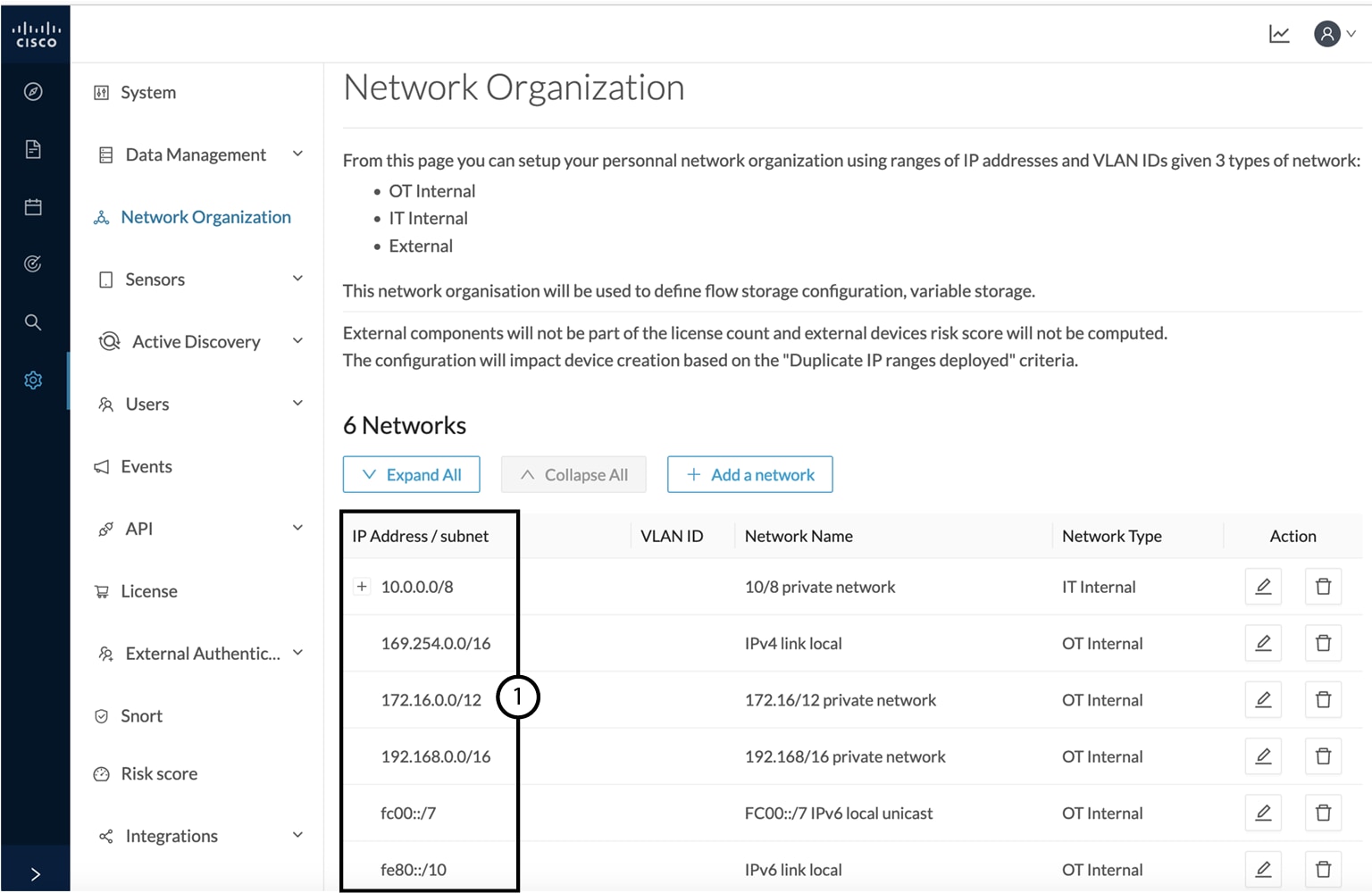
In Cisco Cyber Vision all private IP addresses are classified as OT internal. They appear in the Network Organization page (1).
Every other IP address is considered as external, except for:
-
Broadcast IPv4: 255.255.255.255
-
IPv4 and IPv6 zero: 0.0.0.0 et 0:0:0:0:0:0:0:0
-
Loopback IPv4 and IPv6: 127.0.0.1 and ::1
-
Link Lock Multicast IPv4 and IPv6: 224.0.0.0/8 and ff00::/8
If you want to declare a public IP address as internal, you must add an exception by changing their network type.
Declaring a subnetwork as OT internal is useful in case public IP addresses are used in a private network of an industrial site. Conversely, declaring a set of IP addresses as external will exclude their flows from the database, and exclude their devices from the license device count and the risk score.
Overall, defining subnetworks in Cisco Cyber Vision is useful for several reasons:
-
It allows you to choose afterwards how related flows should be stored through the Ingestion configuration page. Excluding unnecessary flows will have positive impact on performances.
-
It will impact devices' risk scores, since a private network is considered as safer than an external one.
-
Cisco Cyber Vision's license will be more accurate, because devices from an external network will be excluded from the licensing device count.
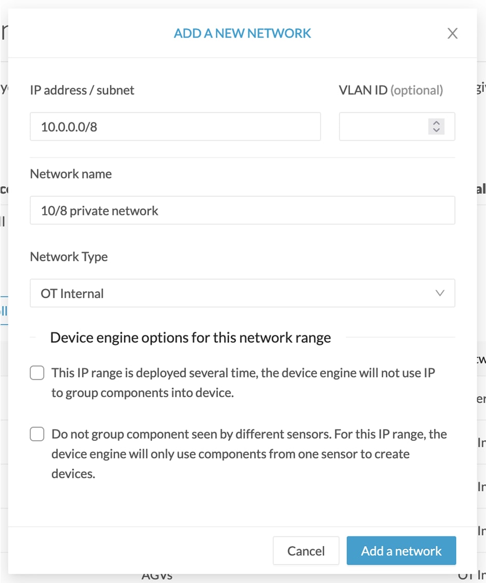
By default, Cisco Cyber Vision groups identical IP addresses detected inside the industrial network into a single device, because in most cases these belong to several components of a device. However, it can happen that the same IP address is used by several devices. In this case, you can choose to select the first option when declaring a subnetwork to prevent duplicate IP addresses from grouping within this subnetwork.
The second option is to be used when components with the same IP address are found by different sensors. This happens when same addressing parameters are used on several subnetworks, for example in case of identical production lines. By using this option, components detected by different sensors will not be aggregated into a single device.

IP ranges can be organized into groups which subranges can be defined like in the example below:

Here, the user specified that the IP range 10.2.0.0/22 is OT internal and that 10.4.0.0/22 is external.
Thus, flow storage can be specificly set in the Ingestion configuration for the IP range set here as OT internal, whereas flows and devices from the IP range set as external will be excluded from the database and the license device count and risk score.
 Note |
It is also possible to organize subnetworks through the API. |
Define a subnetwork
To define a subnetwork:
Procedure
|
Step 1 |
In Cisco Cyber Vision, navigate to Admin > Network organization. |
||
|
Step 2 |
Click the Add a network button. The Edit a network window pops up:  |
||
|
Step 3 |
Enter an IP address range and its subnet. |
||
|
Step 4 |
If possible, add a VLAN ID. |
||
|
Step 5 |
Give the network a name. |
||
|
Step 6 |
Set the network type as OT internal, IT internal or External.
|
||
|
Step 7 |
If applicable, tick the first option.
|
||
|
Step 8 |
If applicable, tick the second option.
|
||
|
Step 9 |
Click Save. |
 Feedback