Sensor Explorer
The Sensor Explorer page allows you to install, manage, and obtain information about the sensors monitoring your industrial network.

First, you need to know that sensors can be used in two modes, and for different purposes:
-
Online mode: A sensor in online mode is placed at a particular and strategic point of the industrial network and will continually capture traffic.
Applicable to: Cisco IE3400, IE3300 10G, Cisco IC3000, Catalyst 9300 and Cisco IR1101.
-
Offline mode: A sensor in offline mode allows you to easily connect it at different points of the industrial network that may be isolated or difficult to access to occasionally make traffic captures. Traffic is captured on a USB drive. The file will then be imported in Cisco Cyber Vision.
Only applicable to Cisco IC3000.
On the Sensor Explorer page, you will see a list of your folders and sensors (when installed) and buttons that will allow you to perform several actions.
Installation modes, features, and information will be available depending on the sensor model and the mode in which it’s being used.
Additional information and actions are available as you click a sensor in the list. A right side panel will appear allowing you to see this information such as the serial number, and buttons to perform other actions.
Filter and sort the sensor list
Filtering
Clicking the Filter button allows you to filter the folders and sensors in the list by label, IP address, version, location, health and processing status.
The folders and sensors list without filtering:

Type in the field or select from the drop down menu to reach the folder(s) or sensor(s) and click the Apply button:

The folders and sensors list after filtering by label:

Sorting
Sort icons allow you to sort sensors by label, IP address, version, location, health and processing status by alphabetical or by ascending/descending order. Sort icons appear when applied or as you hover over them.

Sensors status
There are two types of sensor status:
-
The health status, which indicates at which step of the enrollment process the sensor is.
-
The processing status, which indicates the network connection state between the sensor and the Center.

Health status:
-
New
This is the sensor's first status when it is detected by the Center. The sensor is asking the DHCP server for an IP address.
-
Request Pending
The sensor has asked the Center for a certificate and is waiting for the authorization to be enrolled.
-
Authorized
The sensor has just been authorized by the Admin or the Product user. The sensor remains as "Authorized" for only a few seconds before displaying as "Enrolled".
-
Enrolled
The sensor has successfully connected with the Center. It has a certificate and a private key.
-
Disconnected
The sensor is enrolled but isn't connected to the Center. The sensor may be shut down, encountering a problem, or there is a problem on the network.
Processing status:
-
Disconnected
The sensor is enrolled but isn't connected to the Center. The sensor may be shut down, encountering a problem, or there is a problem on the network.
-
Not enrolled
The sensor is not enrolled. The health status is New or Request Pending. The user must enroll the sensor for it to operate.
-
Normally processing
The sensor is connected to the Center. Data are being sent and processed by the Center.
-
Waiting for data
The sensor is connected to the Center. The Center has treated all data sent by the sensor and is waiting for more data.
-
Pending data
The sensor is connected to the Center. The sensor is trying to send data to the Center but the Center is busy with other data treatment.
Sensors features
You will find in the Sensor Explorer page several features to manage and use your sensors. Some buttons are accessible from the Sensor Explorer page itself to manage one or more sensors. Other buttons are available when clicking a sensor in the list. A right side panel opens with additional sensor information and actions that are available or not depending on the sensor model, mode (online or offline) and the installation type performed.

-
The Start recording button records a traffic capture on the sensor. Records can be used for traffic analysis and may be requested by Cisco support in case of malfunctions. You can download the recording clicking the link below.

Note
This feature is targeted for short captures only. Performing long captures may cause the sensor overload and packets loss.
-
The Move to button is to move the sensor through different folders. For more information, refer to Organize sensors.
-
The Download package button provides a configuration file to be deployed on the sensor when installing the sensor manually (online mode). Only applicable to the Cisco IC3000. Refer to its Installation Guide.
-
The Capture Mode button can be used to set a filter on a sensor sending data to the Center. Refer to the procedure for Setting a capture mode.
-
The Redeploy button can be used to partly reconfigure the sensor, for example to change its parameters such as its IP address.
-
The Enable IDS button can be used to enable the SNORT engine embedded in some sensors to analyze traffic by using SNORT rules. SNORT rules management is available on the SNORT administration page.
-
The Reboot button can be used to reboot the sensor in case of a malfunction.
-
The Shutdown button triggers a clean shutdown of the sensor from the GUI.
Note
After performing a shutdown, you must switch the sensor ON directly and manually on the hardware.
-
The Uninstall button can be used to remove an uninstalled sensor from the list or to fully uninstall a sensor. Diverse options are available according to the sensor model or deployment mode. In the case of a sensor deployed through the management extension, the IOx app can be removed from the device, whereas a reset to factory defaults can be performed in other cases. In any case, the sensor will be removed from the Center.
Install sensor
From the Sensor Explorer page, you can:
-
Install a sensor manually.
-
Install a sensor via the IOx extension. To use the Install via extension button you must first install the sensor management extension via the Extensions page.
-
Capture traffic with an offline sensor (only applicable to Cisco IC3000).
For more information about how to install a sensor, refer to the corresponding Sensor Installation Guide.

Sensor Self Update
Cisco Cyber Vision now allows sensor updates regardless of the install method (i.e., without the extension). Release 4.4.1 provides the necessary foundation for sensor self-updates. However, the self-update feature will only be functional in future releases.
Starting with Cisco Cyber Vision release 4.4.1, you can update all sensors automatically. The required steps are:
-
Select sensors to update.
-
The Center adds a new job to the sensor queue.
-
The sensor automatically collects and validates the update file.
-
The sensor restarts with the new version.
Update Warnings
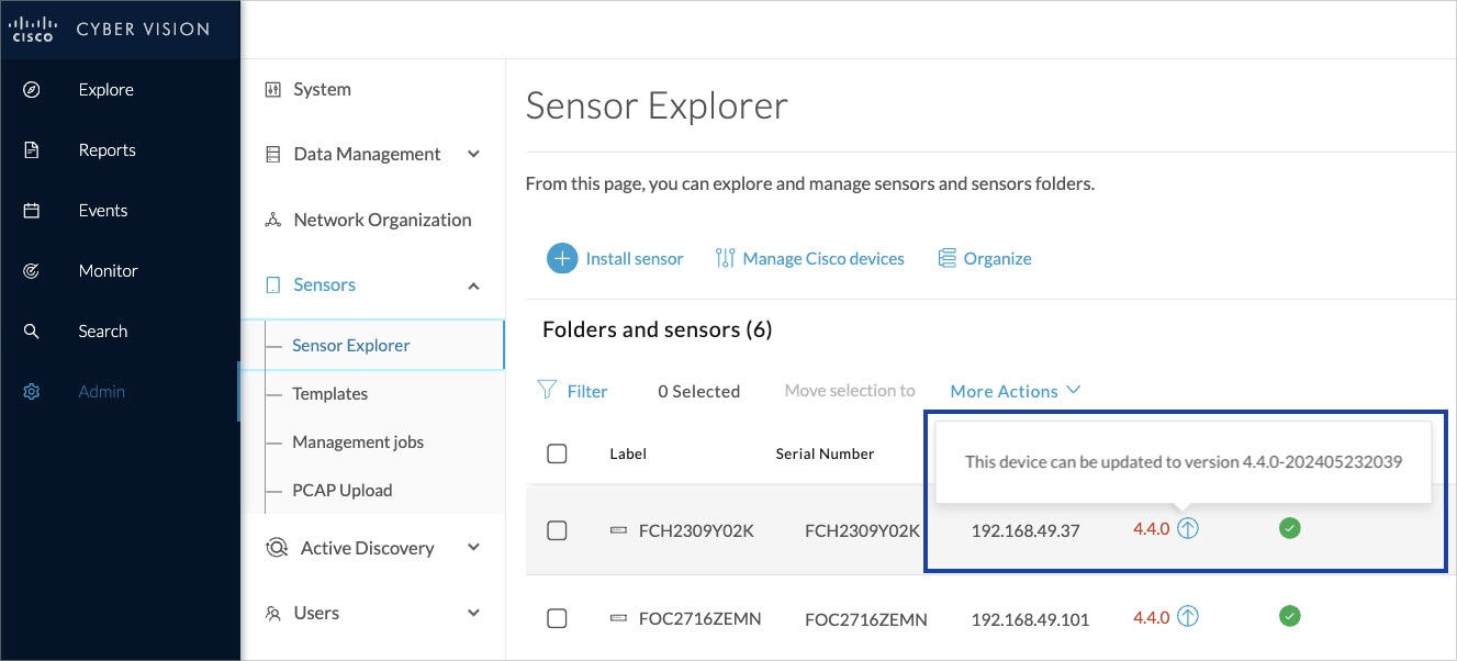
In the Cisco Cyber Vision center on the Sensor Explorer page (Admin – Sensors – Sensor Explorer), users receive an alert to update the sensor. When this happens, the version number turns red, and a blue arrow with a tooltip indicates the sensor is upgradeable.
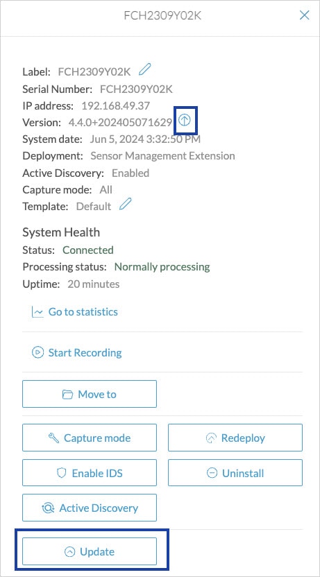
On the sensor's right-side, the same blue arrow and an Update button is visible.
Update Procedure
Procedure
|
Step 1 |
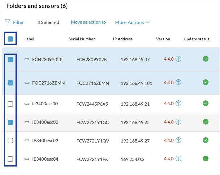
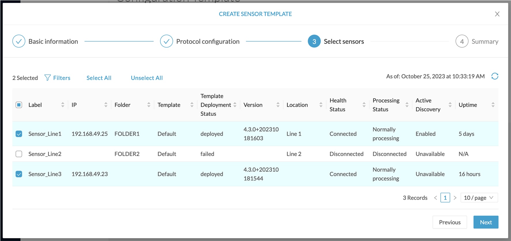
Use the checkboxes on the left to select multiple sensors.
|
|
Step 2 |
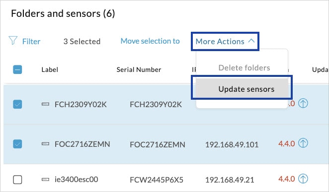
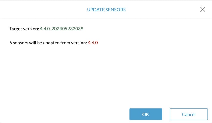
Go to the More Actions and click Update sensors. The sensor self-update menu appears.
|
|
Step 3 |
Click OK.
|
|
Step 4 |
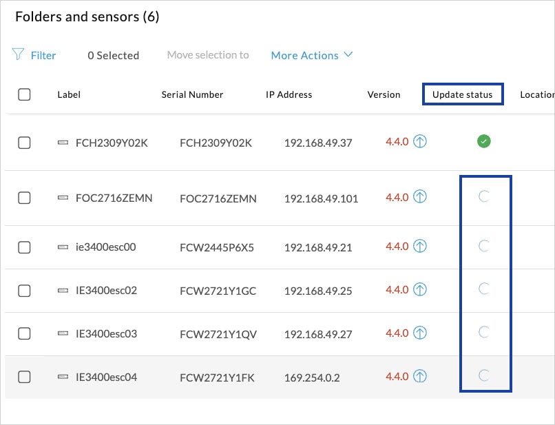
During the update, a blue circle appears in the Update status column.
|
|
Step 5 |
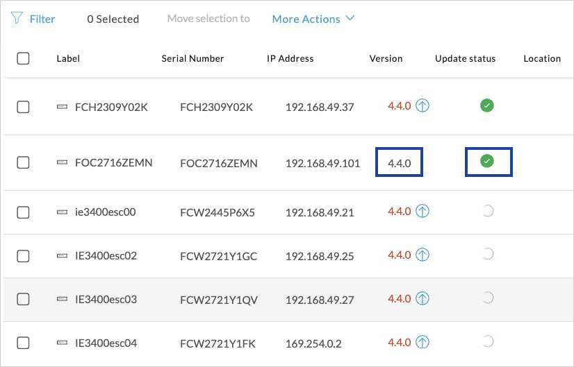
After the update, the version number turns black, and a green symbol appears in the Update status column.
|
|
Step 6 |
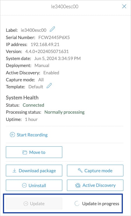
The Update in progress status is visible.
|
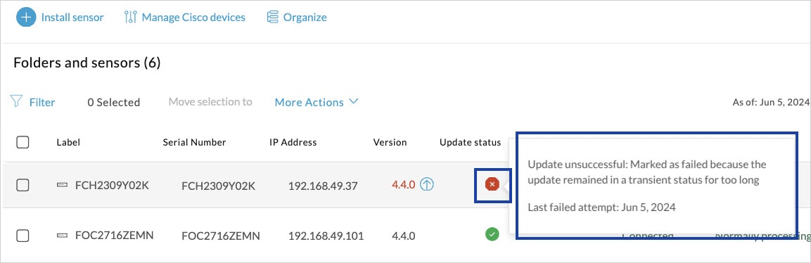
Update Failure
If the update is unsuccessful, the Update status column displays a red cross and a message that provides the details.
Manage credentials
The Manage credentials button, which you can have access by clicking Manage Cisco devices in the Sensor Explorer page, is to register your global credentials if configured before in the Local Manager.

This feature can be used to register your global credentials in Cisco Cyber Vision. This will allow you to enter these credentials only once and they will be used when performing actions that require these credentials, that is installing and updating sensors via the IOx extension.
Only one set of global credentials can be used per Cisco Cyber Vision instance, which means that you cannot have several set of sensors accessible by different global credentials in a single instance. If there are several sensor administrators, they must use the same global credentials registered in Cisco Cyber Vision. However, you can have a set of sensors using a single global credentials and other sensors with their own single credentials.
Global credentials are stored in Cisco Cyber Vision but are set at the switch level in the Local Manager. Consequently, if you lose your global credentials, you must refer to the switch customer support and documentation.
The Manage credentials button can be used the first time you register your global credentials and each time global credentials are changed in the Local Manager. To do so, enter the login and password and click Save.

Once the global credentials are registered, the feature will be enabled in the Install via extension procedure. Select the Use global credentials option to use your global credentials.

Organize sensors
You can create folders and move your sensors into the folders for more clarity. Folders can correspond to a location, a person in charge, a set of disconnected sensors, etc.
To create a folder and move a sensor in it:
-
Click the Organize button and click Create folder.

-
Write a folder name, and, if needed, a location and a description.

The new folder is displayed in the sensor list.

-
Select a sensor in the list and click the button Move selection to.

-
Select the folder you want to place the sensor in or create a new folder. Root can be used to move sensors back into the primary list.

The sensor is moved into the folder. The sensor version, health status and processing status are displayed in the folder line.

If you move a sensor in a disconnected state inside this same folder, then its information will be displayed in the folder line rather than the sensor in connected state. Less secure sensor status are showcased in priority to drag your attention.

The sensors inside a folder:

Set a capture mode
The Capture mode feature lets you choose which network communications will be analyzed by the sensors. You can set it by clicking an online sensor in the sensors list of the Sensor Explorer page or during a sensor installation.
Setting the capture mode on a sensor from the right side panel:

Capture modes:

The aim is mainly to focus the monitoring on relevant traffic but also to reduce the load on the Center.
For example, a common filter in a firewall can consist of removing the network management flows (SNMP). This can be done by setting a filter like "not (port 161 and host 10.10.10.10)" where "10.10.10.10" is the network management platform.
Using Capture mode Cisco Cyber Vision performance can be improved on large networks.
Capture modes operate because of filters applied on each sensor. Filters are set to define which types of incoming packets are to be analyzed by the sensors. You can set a different filter on each sensor according to your needs.
You can set the capture mode in the installation wizard when enrolling the sensors during the Center installation. This option is recommended if you already know which filter to set. Otherwise, you can change it at any time through the Sensor Explorer page in the GUI (provided that the SSH connection is allowed from the Center to the sensors).
Note |
You can set a capture mode to offline sensors from a file containing the filter and registered on the USB drive. This will be then plugged on the Offline USB port of the device. For more information about setting a capture mode on an offline sensor contact the support. |
The different capture modes are:
-
ALL: No filter is applied. The sensor analyzes all incoming flows and they will all be stored inside the Center database.
-
OPTIMAL (Default): The applied filter selects the most relevant flows according to Cisco expertise. Multicast flows are not recorded. This capture mode is recommended for long term capture and monitoring.
-
INDUSTRIAL ONLY: The filter selects industrial protocols only like modbus, S7, EtherNet/IP, etc. This means that IT flows of the monitored network won't be analyzed by the sensor and won't appear in the GUI.
-
CUSTOM (advanced users): Use this capture mode if you want to fully customize the filter to be applied. To do so you will need to use the tcpdump syntax to define the filtering rules.


 Feedback