VPN Overview for Firepower Threat Defense

A virtual private network (VPN) connection establishes a secure tunnel between endpoints over a public network such as the Internet.

This chapter applies to Remote Access and Site-to-site VPNs on Firepower Threat Defense devices. It describes the Internet Protocol Security (IPsec), the Internet Security Association and Key Management Protocol (ISAKMP, or IKE) and SSL standards that are used to build site-to-site and remote access VPNs.

Site-to-site VPNs on 7000 and 8000 Series devices, referred to as Gateway VPNs or Firepower VPNs in the Firepower Management Center are described in Gateway VPNs.

VPN Types

The Firepower Management Center supports the following types of VPN connections:

  • Remote Access VPNs on Firepower Threat Defense devices.

    Remote access VPNs are secure, encrypted connections, or tunnels, between remote users and your company’s private network. The connection consists of a VPN endpoint device, which is a workstation or mobile device with VPN client capabilities, and a VPN headend device, or secure gateway, at the edge of the corporate private network.

    Firepower Threat Defense devices can be configured to support Remote Access VPNs over SSL or IPsec IKEv2 by the Firepower Management Center. Functioning as secure gateways in this capacity, they authenticate remote users, authorize access, and encrypt data to provide secure connections to your network. No other types of appliances, managed by the Firepower Management Center, support Remote Access VPN connections.

    Firepower Threat Defense secure gateways support the AnyConnect Secure Mobility Client full tunnel client. This client is required to provide secure SSL IPsec IKEv2 connections for remote users. This client gives remote users the benefits of a client without the need for network administrators to install and configure clients on remote computers since it can be deployed to the client platform upon connectivity. It is the only client supported on endpoint devices.

  • Site-to-site VPNs on Firepower Threat Defense devices.

    A site-to-site VPN connects networks in different geographic locations. You can create site-to-site IPsec connections between managed devices, and between managed devices and other Cisco or third-party peers that comply with all relevant standards. These peers can have any mix of inside and outside IPv4 and IPv6 addresses. Site-to-site tunnels are built using the Internet Protocol Security (IPsec) protocol suite and IKEv1 or IKEv2. After the VPN connection is established, the hosts behind the local gateway can connect to the hosts behind the remote gateway through the secure VPN tunnel.

  • Site-to-site VPNs on 7000 and 8000 Series devices.

    These site-to-site VPNs are referred to as Gateway VPNs or Firepower VPNs in the Firepower Management Center. See Gateway VPNs, for information on this type of VPN connection.

VPN Basics

Tunneling makes it possible to use a public TCP/IP network, such as the Internet, to create secure connections between remote users and private corporate networks. Each secure connection is called a tunnel.

IPsec-based VPN technologies use the Internet Security Association and Key Management Protocol (ISAKMP, or IKE) and IPsec tunneling standards to build and manage tunnels. ISAKMP and IPsec accomplish the following:

  • Negotiate tunnel parameters.

  • Establish tunnels.

  • Authenticate users and data.

  • Manage security keys.

  • Encrypt and decrypt data.

  • Manage data transfer across the tunnel.

  • Manage data transfer inbound and outbound as a tunnel endpoint or router.

A device in a VPN functions as a bidirectional tunnel endpoint. It can receive plain packets from the private network, encapsulate them, create a tunnel, and send them to the other end of the tunnel where they are unencapsulated and sent to their final destination. It can also receive encapsulated packets from the public network, unencapsulate them, and send them to their final destination on the private network.

After the site-to-site VPN connection is established, the hosts behind the local gateway can connect to the hosts behind the remote gateway through the secure VPN tunnel. A connection consists of the IP addresses and hostnames of the two gateways, the subnets behind them, and the method the two gateways use to authenticate to each other.

Internet Key Exchange (IKE)

Internet Key Exchange (IKE) is a key management protocol that is used to authenticate IPsec peers, negotiate and distribute IPsec encryption keys, and to automatically establish IPsec security associations (SAs).

The IKE negotiation comprises two phases. Phase 1 negotiates a security association between two IKE peers, which enables the peers to communicate securely in Phase 2. During Phase 2 negotiation, IKE establishes SAs for other applications, such as IPsec. Both phases use proposals when they negotiate a connection.

An IKE policy is a set of algorithms that two peers use to secure the IKE negotiation between them. IKE negotiation begins by each peer agreeing on a common (shared) IKE policy. This policy states which security parameters protect subsequent IKE negotiations. For IKE version 1 (IKEv1), IKE policies contain a single set of algorithms and a modulus group. Unlike IKEv1, in an IKEv2 policy, you can select multiple algorithms and modulus groups from which peers can choose during the Phase 1 negotiation. It is possible to create a single IKE policy, although you might want different policies to give higher priority to your most desired options. For site-to-site VPNs, you can create a single IKE policy.

To define an IKE policy, specify:

  • A unique priority (1 to 65,543, with 1 the highest priority).

  • An encryption method for the IKE negotiation, to protect the data and ensure privacy.

  • A Hashed Message Authentication Codes (HMAC) method (called integrity algorithm in IKEv2) to ensure the identity of the sender, and to ensure that the message has not been modified in transit.

  • For IKEv2, a separate pseudorandom function (PRF) used as the algorithm to derive keying material and hashing operations required for the IKEv2 tunnel encryption. The options are the same as those used for the hash algorithm.

  • A Diffie-Hellman group to determine the strength of the encryption-key-determination algorithm. The device uses this algorithm to derive the encryption and hash keys.

  • An authentication method, to ensure the identity of the peers.

  • A limit to the time the device uses an encryption key before replacing it.

When IKE negotiation begins, the peer that starts the negotiation sends all of its policies to the remote peer, and the remote peer searches for a match with its own policies, in priority order. A match between IKE policies exists if they have the same encryption, hash (integrity and PRF for IKEv2), authentication, and Diffie-Hellman values, and an SA lifetime less than or equal to the lifetime in the policy sent. If the lifetimes are not identical, the shorter lifetime—From the remote peer policy—Applies. By default, the FMC deploys an IKEv1 policy at the lowest priority for all VPN endpoints to ensure a successful negotiation.

IPsec

IPsec is one of the most secure methods for setting up a VPN. IPsec provides data encryption at the IP packet level, offering a robust security solution that is standards-based. With IPsec, data is transmitted over a public network through tunnels. A tunnel is a secure, logical communication path between two peers. Traffic that enters an IPsec tunnel is secured by a combination of security protocols and algorithms.

An IPsec Proposal policy defines the settings required for IPsec tunnels. An IPsec proposal is a collection of one or more crypto-maps that are applied to the VPN interfaces on the devices. A crypto map combines all the components required to set up IPsec security associations, including:

  • A proposal (or transform set) is a combination of security protocols and algorithms that secure traffic in an IPsec tunnel. During the IPsec security association (SA) negotiation, peers search for a proposal that is the same at both peers. When it is found, it is applied to create an SA that protects data flows in the access list for that crypto map, protecting the traffic in the VPN. There are separate IPsec proposals for IKEv1 and IKEv2. In IKEv1 proposals (or transform sets), for each parameter, you set one value. For IKEv2 proposals, you can configure multiple encryption and integration algorithms for a single proposal.

  • A crypto map, combines all components required to set up IPsec security associations (SA), including IPsec rules, proposals, remote peers, and other parameters that are necessary to define an IPsec SA. When two peers try to establish an SA, they must each have at least one compatible crypto map entry.

    Dynamic crypto map policies are used in site-to-site VPNs when an unknown remote peer tries to start an IPsec security association with the local hub. The hub cannot be the initiator of the security association negotiation. Dynamic crypto-policies allow remote peers to exchange IPsec traffic with a local hub even if the hub does not know the remote peer’s identity. A dynamic crypto map policy essentially creates a crypto map entry without all the parameters configured. The missing parameters are later dynamically configured (as the result of an IPsec negotiation) to match a remote peer’s requirements.

    Dynamic crypto map policies apply only in a hub-and-spoke and full-mesh VPN topologies. In a point-to-point or full mesh VPN topology, you can apply only static crypto map policies. Emulate the use of dynamic crypto-maps in a point-to-point topology by creating a hub-and-spoke topology with two devices. Specify a dynamic IP address for the spoke and enable dynamic crypto-maps on this topology.


    Note


    Simultaneous IKEv2 dynamic crypto map is not supported for the same interface for both remote access and site-to-site VPNs on Firepower Threat Defense (FTD).


VPN Packet Flow

On a Firepower Threat Defense device, by default no traffic is allowed to pass through access-control without explicit permission. VPN tunnel traffic as well, is not relayed to the endpoints until it has passed through Snort. Incoming tunnel packets are decrypted before being sent to the Snort process. Snort processes outgoing packets before encryption.

Access Control identifying the protected networks for each endpoint node of a VPN tunnel determines which traffic is allowed to pass through the Firepower Threat Defense device and reach the endpoints. For Remote Access VPN traffic, a Group Policy filter or an Access Control rule must be configured to permit VPN traffic flow.

In addition, the system does not send tunnel traffic to the public source when the tunnel is down.

VPN Licensing

There is no specific licensing for enabling Firepower Threat Defense VPN, it is available by default.

The Firepower Management Center determines whether to allow or block the usage of strong crypto on a Firepower Threat Defense device based on attributes provided by the smart licensing server.

This is controlled by whether you selected the option to allow export-controlled functionality on the device when you registered with Cisco Smart License Manager. If you are using the evaluation license, or you did not enable export-controlled functionality, you cannot use strong encryption.

How Secure Should a VPN Connection Be?

Because a VPN tunnel typically traverses a public network, most likely the Internet, you need to encrypt the connection to protect the traffic. You define the encryption and other security techniques to apply using IKE polices and IPsec proposals.

If your device license allows you to apply strong encryption, there is a wide range of encryption and hash algorithms, and Diffie-Hellman groups, from which to choose. However, as a general rule, the stronger the encryption that you apply to the tunnel, the worse the system performance. Find a balance between security and performance that provides sufficient protection without compromising efficiency.

We cannot provide specific guidance on which options to choose. If you operate within a larger corporation or other organization, there might already be defined standards that you need to meet. If not, take the time to research the options.

The following topics explain the available options.

Deciding Which Encryption Algorithm to Use

When deciding which encryption algorithms to use for the IKE policy or IPsec proposal, your choice is limited to algorithms supported by the devices in the VPN.

For IKEv2, you can configure multiple encryption algorithms. The system orders the settings from the most secure to the least secure and negotiates with the peer using that order. For IKEv1, you can select a single option only.

For IPsec proposals, the algorithm is used by the Encapsulating Security Protocol (ESP), which provides authentication, encryption, and anti-replay services. ESP is IP protocol type 50. In IKEv1 IPsec proposals, the algorithm name is prefixed with ESP-.

If your device license qualifies for strong encryption, you can choose from the following encryption algorithms. If you are not qualified for strong encryption, you can select DES only.

  • AES-GCM—(IKEv2 only.) Advanced Encryption Standard in Galois/Counter Mode is a block cipher mode of operation providing confidentiality and data-origin authentication, and provides greater security than AES. AES-GCM offers three different key strengths: 128-, 192-, and 256-bit keys. A longer key provides higher security but a reduction in performance. GCM is a mode of AES that is required to support NSA Suite B. NSA Suite B is a set of cryptographic algorithms that devices must support to meet federal standards for cryptographic strength. .

  • AES-GMAC—(IKEv2 IPsec proposals only.) Advanced Encryption Standard Galois Message Authentication Code is a block cipher mode of operation providing only data-origin authentication. It is a variant of AES-GCM that allows data authentication without encrypting the data. AES-GMAC offers three different key strengths: 128-, 192-, and 256-bit keys.

  • AES—Advanced Encryption Standard is a symmetric cipher algorithm that provides greater security than DES and is computationally more efficient than 3DES. AES offers three different key strengths: 128-, 192-, and 256-bit keys. A longer key provides higher security but a reduction in performance.

  • 3DES—Triple DES, which encrypts three times using 56-bit keys, is more secure than DES because it processes each block of data three times with a different key. However, it uses more system resources and is slower than DES.

  • DES—Data Encryption Standard, which encrypts using 56-bit keys, is a symmetric secret-key block algorithm. If your license account does not meet the requirements for export controls, this is your only option. It is faster than 3DES and uses less system resources, but it is also less secure. If you do not need strong data confidentiality, and if system resources or speed is a concern, choose DES.

  • Null, ESP-Null—Do not use. A null encryption algorithm provides authentication without encryption. This is typically used for testing purposes only. However, it does not work at all on many platforms, including virtual and the Firepower 2100.

Deciding Which Hash Algorithms to Use

In IKE policies, the hash algorithm creates a message digest, which is used to ensure message integrity. In IKEv2, the hash algorithm is separated into two options, one for the integrity algorithm, and one for the pseudo-random function (PRF).

In IPsec proposals, the hash algorithm is used by the Encapsulating Security Protocol (ESP) for authentication. In IKEv2 IPsec Proposals, this is called the integrity hash. In IKEv1 IPsec proposals, the algorithm name is prefixed with ESP-, and there is also an -HMAC suffix (which stands for “hash method authentication code”).

For IKEv2, you can configure multiple hash algorithms. The system orders the settings from the most secure to the least secure and negotiates with the peer using that order. For IKEv1, you can select a single option only.

You can choose from the following hash algorithms.

  • SHA (Secure Hash Algorithm)—Standard SHA (SHA1) produces a 160-bit digest. SHA is more resistant to brute-force attacks than MD5. However, it is also more resource intensive than MD5. For implementations that require the highest level of security, use the SHA hash algorithm.

    The following SHA-2 options, which are even more secure, are available for IKEv2 configurations. Choose one of these if you want to implement the NSA Suite B cryptography specification.

    • SHA256—Specifies the Secure Hash Algorithm SHA 2 with the 256-bit digest.

    • SHA384—Specifies the Secure Hash Algorithm SHA 2 with the 384-bit digest.

    • SHA512—Specifies the Secure Hash Algorithm SHA 2 with the 512-bit digest.

  • MD5 (Message Digest 5)—Produces a 128-bit digest. MD5 uses less processing time for an overall faster performance than SHA, but it is considered to be weaker than SHA.

  • Null or None (NULL, ESP-NONE)—(IPsec Proposals only.) A null Hash Algorithm; this is typically used for testing purposes only. However, you should choose the null integrity algorithm if you select one of the AES-GCM/GMAC options as the encryption algorithm. Even if you choose a non-null option, the integrity hash is ignored for these encryption standards.

Deciding Which Diffie-Hellman Modulus Group to Use

You can use the following Diffie-Hellman key derivation algorithms to generate IPsec security association (SA) keys. Each group has a different size modulus. A larger modulus provides higher security, but requires more processing time. You must have a matching modulus group on both peers.

If you select AES encryption, to support the large key sizes required by AES, you should use Diffie-Hellman (DH) Group 5 or higher. IKEv1 policies do not support all of the groups listed below.

To implement the NSA Suite B cryptography specification, use IKEv2 and select one of the elliptic curve Diffie-Hellman (ECDH) options: 19, 20, or 21. Elliptic curve options and groups that use 2048-bit modulus are less exposed to attacks such as Logjam.

For IKEv2, you can configure multiple groups. The system orders the settings from the most secure to the least secure and negotiates with the peer using that order. For IKEv1, you can select a single option only.

  • 1—Diffie-Hellman Group 1: 768-bit modulus. DH group 1 is considered insecure, please do not use it.

  • 2—Diffie-Hellman Group 2: 1024-bit modular exponential (MODP) group. This option is no longer considered good protection.

  • 5—Diffie-Hellman Group 5: 1536-bit MODP group. Formerly considered good protection for 128-bit keys, this option is no longer considered good protection.

  • 14—Diffie-Hellman Group 14: 2048-bit modular exponential (MODP) group. Considered good protection for 192-bit keys.

  • 19—Diffie-Hellman Group 19: National Institute of Standards and Technology (NIST) 256-bit elliptic curve modulo a prime (ECP) group.

  • 20—Diffie-Hellman Group 20: NIST 384-bit ECP group.

  • 21—Diffie-Hellman Group 21: NIST 521-bit ECP group.

  • 24—Diffie-Hellman Group 24: 2048-bit MODP group with 256-bit prime order subgroup. This option is no longer recommended.

Deciding Which Authentication Method to Use

Preshared keys and digital certificates are the methods of authentication available for VPNs.

Site-to-site, IKEv1 and IKEv2 VPN connections can use both options.

Remote Access, which uses SSL and IPsec IKEv2 only, supports digital certificate authentication only.

Preshared keys allow for a secret key to be shared between two peers and used by IKE during the authentication phase. The same shared key must be configured at each peer or the IKE SA cannot be established.

Digital certificates use RSA key pairs to sign and encrypt IKE key management messages. Certificates provide non-repudiation of communication between two peers, meaning that it can be proved that the communication actually took place. When using this authentication method, you need a Public Key Infrastructure (PKI) defined where peers can obtain digital certificates from a Certification Authority (CA). CAs manage certificate requests and issue certificates to participating network devicesproviding centralized key management for all of the participating devices.

Preshared keys do not scale well, using a CA improves the manageability and scalability of your IPsec network. With a CA, you do not need to configure keys between all encrypting devices. Instead, each participating device is registered with the CA, and requests a certificate from the CA. Each device that has its own certificate and the public key of the CA can authenticate every other device within a given CA’s domain.

Pre-shared Keys

Preshared keys allow for a secret key to be shared between two peers. The key is used by IKE in the authentication phase. The same shared key must be configured on each peer, or the IKE SA cannot be established.

To configure the pre-shared keys, choose whether you will use a manual or automatically generated key, and then speicify the key in the IKEv1/IKEv2 options. Then, when your configuration is deployed, the key is configured on all devices in the topology.

PKI Infrastructure and Digital Certificates

Public Key Infrastructure

A PKI provides centralized key management for participating network devices. It is a defined set of policies, procedures, and roles that support public key cryptography by generating, verifying, and revoking public key certificates commonly known as digital certificates.

In public key cryptography, each endpoint of a connection has a key pair consisting of both a public and a private key. The key pairs are used by the VPN endpoints to sign and encrypt messages. The keys act as complements, and anything encrypted with one of the keys can be decrypted with the other, securing the data flowing over the connection.

Generate a general purpose RSA or ECDSA key pair, used for both signing and encryption, or you generate separate key pairs for each purpose. Separate signing and encryption keys help to reduce exposure of the keys. SSL uses a key for encryption but not signing, however, IKE uses a key for signing but not encryption. By using separate keys for each, exposure of the keys is minimized.

Digital Certificates or Identify Certificates

When you use Digital Certificates as the authentication method for VPN connections, peers are configured to obtain digital certificates from a Certificate Authority (CA). CAs are trusted authorities that “sign” certificates to verify their authenticity, thereby guaranteeing the identity of the device or user.

CA servers manage public CA certificate requests and issue certificates to participating network devices as part of a Public Key Infrastructure (PKI), this activity is called Certificate Enrollment. These digital certificates, also called identity certificates contain:

  • The digital identification of the owner for authentication, such as name, serial number, company, department, or IP address.

  • A public key needed to send and receive encrypted data to the certificate owner.

  • The secure digital signature of a CA.

Certificates also provide non-repudiation of communication between two peers, meaning that it they prove that the communication actually took place.
Certificate Enrollment

Using a PKI improves the manageability and scalability of your VPN since you do not have to configure pre-shared keys between all the encrypting devices. Instead, you individually enroll each participating device with a CA server, which is explicitly trusted to validate identities and create an identity certificate for the device. When this has been accomplished, each participating peer sends their identity certificate to the other peer to validate their identities and establish encrypted sessions with the public keys contained in the certificates. See Certificate Enrollment Objectsfor details on enrolling Firepower Threat Defense devices.

Certificate Authority Certificates

In order to validate a peer’s certificate, each participating device must retrieve the CA's certificate from the server. A CA certificate is used to sign other certificates. It is self-signed and called a root certificate. This certificate contains the public key of the CA, used to decrypt and validate the CA's digital signature and the contents of the received peer's certificate. The CA certificate may be obtained by:

  • Using the Simple Certificate Enrollment Protocol (SCEP) to retrieve the CA’s certificate from the CA server

  • Manually copying the CA's certificate from another participating device

Trustpoints

Once enrollment is complete, a trustpoint is created on the managed device. It is the object representation of a CA and associated certificates. A trustpoint includes the identity of the CA, CA-specific parameters, and an association with a single enrolled identity certificate.

PKCS#12 File

A PKCS#12, or PFX, file holds the server certificate, any intermediate certificates, and the private key in one encrypted file. This type of file may be imported directly into a device to create a trustpoint.

Revocation Checking

A CA may also revoke certificates for peers that no longer participate in you network. Revoked certificates are either managed by an Online Certificate Status Protocol (OCSP) server or are listed in a certificate revocation list (CRL) stored on an LDAP server. A peer may check these before accepting a certificate from another peer.

VPN Topology Options

When you create a new VPN topology you must, at minimum, give it a unique name, specify a topology type, and select the IKE version. You can select from three types of topologies, each containing a group of VPN tunnels:

  • Point-to-point (PTP) topologies establish a VPN tunnel between two endpoints.

  • Hub and Spoke topologies establish a group of VPN tunnels connecting a hub endpoint to a group of spoke endpoints.

  • Full Mesh topologies establish a group of VPN tunnels among a set of endpoints.

Define a pre-shared key for VPN authentication manually or automatically, there is no default key. When choosing automatic, the Firepower Management Center generates a pre-shared key and assigns it to all the nodes in the topology.

Point-to-Point VPN Topology

In a point-to-point VPN topology, two endpoints communicate directly with each other. You configure the two endpoints as peer devices, and either device can start the secured connection.

The following diagram displays a typical point-to-point VPN topology.

Diagram illustrating a point-to-point VPN topology

Hub and Spoke VPN Topology

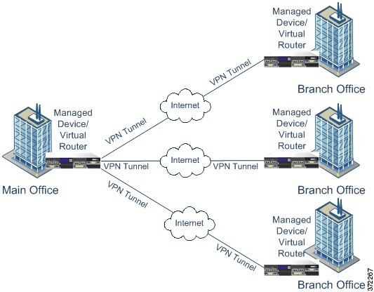
In a Hub and Spoke VPN topology, a central endpoint (hub node) connects with multiple remote endpoints (spoke nodes). Each connection between the hub node and an individual spoke endpoint is a separate VPN tunnel. The hosts behind any of the spoke nodes can communicate with each other through the hub node.

The Hub and Spoke topology commonly represent a VPN that connects an organization’s main and branch office locations using secure connections over the Internet or other third-party network. These deployments provide all employees with controlled access to the organization’s network. Typically, the hub node is located at the main office. Spoke nodes are located at branch offices and start most of the traffic.

The following diagram displays a typical Hub and Spoke VPN topology.

Diagram illustrating a Hub and Spoke VPN topology

Full Mesh VPN Topology

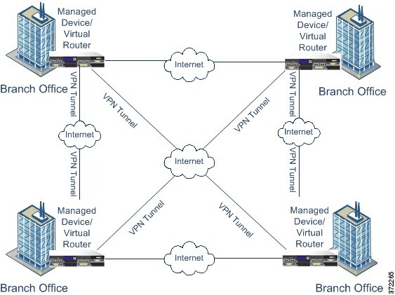
In a Full Mesh VPN topology, all endpoints can communicate with every other endpoint by an individual VPN tunnel. This topology offers redundancy so that when one endpoint fails, the remaining endpoints can still communicate with each other. It commonly represents a VPN that connects a group of decentralized branch office locations. The number of VPN-enabled managed devices you deploy in this configuration depends on the level of redundancy you require.

The following diagram displays a typical Full Mesh VPN topology.

Diagram illustrating a mesh VPN topology

Implicit Topologies

In addition to the three main VPN topologies, other more complex topologies can be created as combinations of these topologies. They include:

  • Partial mesh—A network in which some devices are organized in a full mesh topology, and other devices form either a hub-and-spoke or a point-to-point connection to some of the fully meshed devices. A partial mesh does not provide the level of redundancy of a full mesh topology, but it is less expensive to implement. Partial mesh topologies are used in peripheral networks that connect to a fully meshed backbone.

  • Tiered hub-and-spoke—A network of hub-and-spoke topologies in which a device can behave as a hub in one or more topologies and a spoke in other topologies. Traffic is permitted from spoke groups to their most immediate hub.

  • Joined hub-and-spoke—A combination of two topologies (hub-and-spoke, point-to-point, or full mesh) that connect to form a point-to-point tunnel. For example, a joined hub-and-spoke topology could comprise two hub-and-spoke topologies, with the hubs acting as peer devices in a point-to-point topology.