- Cisco Plug and Play Connect
- Prerequisites
- Load authorized WAN edge serial numbers to vManage
- Method 1: Sync to the Smart Account
- Method 2: Upload File Manually
- Stage Devices (Optional)
- Attach device to template
- Add Variables with a File
- Add Variables Manually
- Modify Variables
- Generate Bootstrap Configuration File
- Bring up Devices
- Plug and Play
- Prerequisites
- Bootstrap
- Prerequisites
- Activate Devices in Staging State
- Device Onboarding Troubleshooting
- Device is Not Authorized by vBond
- Router Configuration Failure
Device Onboarding
Device onboarding is a process initiated by the network administrator by completing the following tasks:
■![]() Load device(s) on Plug and Play Connect if not added during procurement process
Load device(s) on Plug and Play Connect if not added during procurement process
■![]() Load device(s) on vManage, push them to vSmart and vBond, and declare the device(s) as valid or staging device(s).
Load device(s) on vManage, push them to vSmart and vBond, and declare the device(s) as valid or staging device(s).
■![]() Attach the device to a template
Attach the device to a template
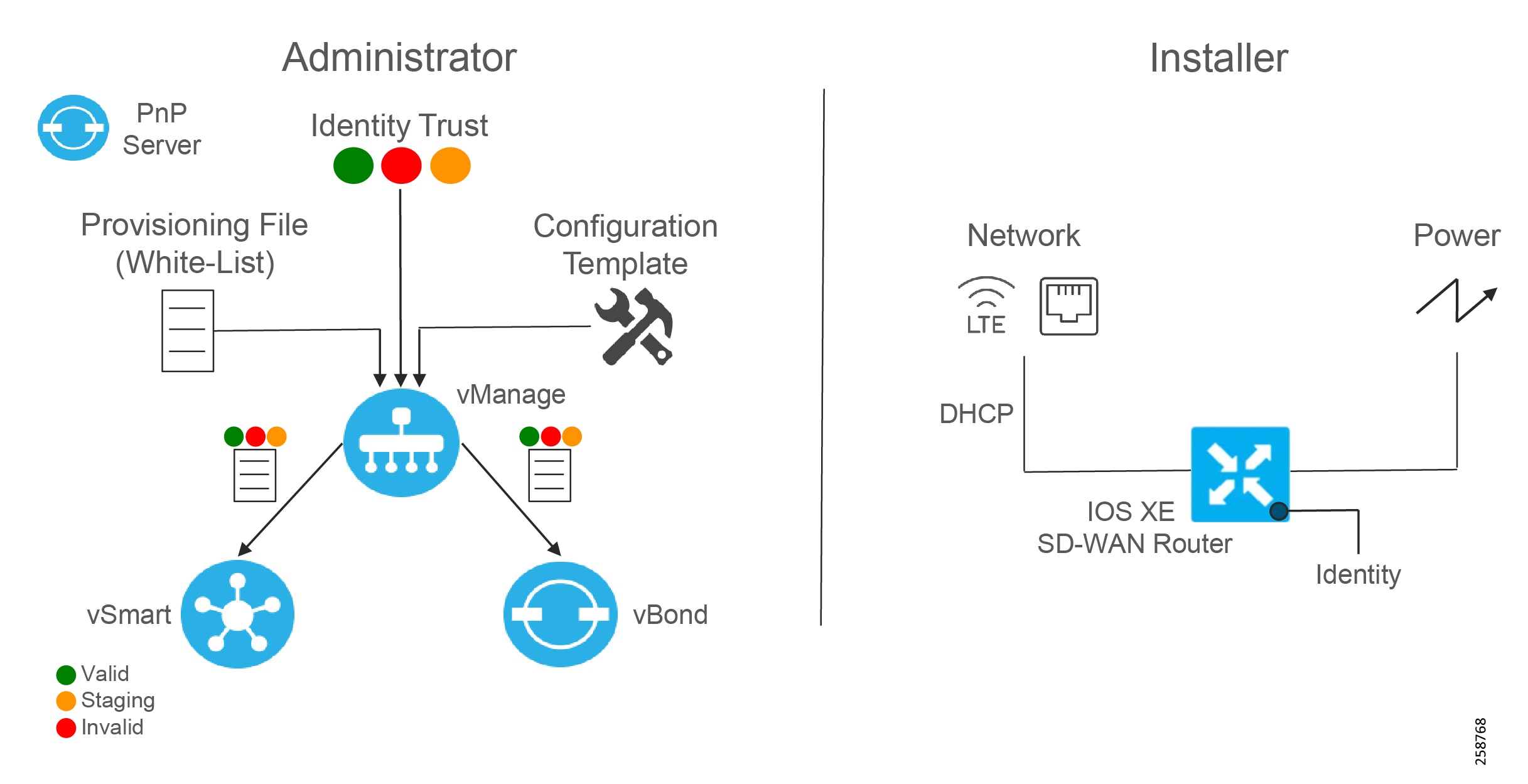
After the steps are completed, an installer on the remote site could connect the device to the network, after which the device will reach vBond, establish DTLS connectivity with controllers, and download the configuration defined on the template.
The following graph illustrates the device onboarding activities. Detailed steps are provided in this chapter.
Cisco Plug and Play Connect
In order for the WAN Edge devices to join and be active in the overlay, a valid, authorized serial number file has to be uploaded to vManage. This authorized serial number file lists the serial and chassis numbers for all WAN Edge routers allowed in the network. vManage will send this file to the controllers, and only devices that match serial numbers on this list will be validated and authenticated successfully by the controllers. The authorized serial number for IOS XE SD-WAN routers is obtained from Plug and Play (PnP) Connect portal. PnP Connect portal is also used to automate onboarding of network devices and apply configuration settings without manual intervention. This guide will provide required steps to add a device on PnP Connect using a smart account and associate it to a vBond profile. Refer to the following link for deeper understanding on PnP connect https://www.cisco.com/c/en/us/products/collateral/software/smart-accounts/guide-c07-744931.html#4Deploymentoptions.
Prerequisites
■![]() Smart account and virtual account
Smart account and virtual account
■![]() If the deployment is on premises, vBond has to be defined in PnP connect. Refer to https://www.cisco.com/c/dam/en_us/services/downloads/SD-WAN_pnp_support_guide.pdf for specific steps. Note that for cloud deployments, controller information is reflected automatically on the PnP portal.
If the deployment is on premises, vBond has to be defined in PnP connect. Refer to https://www.cisco.com/c/dam/en_us/services/downloads/SD-WAN_pnp_support_guide.pdf for specific steps. Note that for cloud deployments, controller information is reflected automatically on the PnP portal.
Adding a device on PnP Connect
A device can be added to PnP Connect automatically if the smart account and virtual account are added to the order on Cisco Commerce Workspace.
If the device is not added through the procurement process, follow these steps:
1.![]() Get serial number and certificate serial number from the device using the show crypto pki certificates CISCO_IDEVID_SUDI command:
Get serial number and certificate serial number from the device using the show crypto pki certificates CISCO_IDEVID_SUDI command:
Certificate
Status: Available
Certificate Serial Number (hex): XXXXXXXX
Certificate Usage: General Purpose
Issuer:
cn=ACT2 SUDI CA
o=Cisco
Subject:
Name: IR1101-K9
Serial Number: PID:IR1101-K9 SN:XXXXXXXXXXX
cn=IR1101-K9
ou=ACT-2 Lite SUDI
o=Cisco
serialNumber=PID:IR1101-K9 SN: XXXXXXXXXXX
Validity Date:
start date: 07:49:10 UTC Mar 9 2019
end date: 20:25:41 UTC May 14 2029
Associated Trustpoints: CISCO_IDEVID_SUDI
2.![]() Navigate to https://software.cisco.com.
Navigate to https://software.cisco.com.
3.![]() Under the Network Plug and Play section, click the Plug and Play Connect link.
Under the Network Plug and Play section, click the Plug and Play Connect link.
4.![]() Ensure the correct virtual account is chosen in the top right corner.
Ensure the correct virtual account is chosen in the top right corner.
6.![]() Select Enter Device Info Manually radio button. Alternatively, you could upload a Comma Separated Values (CSV) file.
Select Enter Device Info Manually radio button. Alternatively, you could upload a Comma Separated Values (CSV) file.
8.![]() Click Identify Device button.
Click Identify Device button.
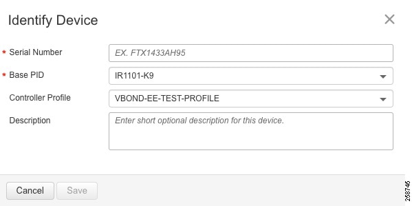
9.![]() Fill out the serial number obtained in Step 1, base PID (IR1101-K9), and the selected vBond controller profile.
Fill out the serial number obtained in Step 1, base PID (IR1101-K9), and the selected vBond controller profile.
Figure 29 Connect - Identify Device
10.![]() Click Save. On the wizard screen, click Next.
Click Save. On the wizard screen, click Next.
11.![]() On Review & Submit, click Submit.
On Review & Submit, click Submit.
13.![]() After the router is added, a list of devices is displayed. Select the recently added device and then click Edit Selected.
After the router is added, a list of devices is displayed. Select the recently added device and then click Edit Selected.
14.![]() Click the space under the Certificate Serial Number column for the device and enter the information from Step 1.
Click the space under the Certificate Serial Number column for the device and enter the information from Step 1.
Figure 30 Add Certificate Serial Number

16.![]() The device will show with yellow status showing Pending (Redirection). If the device is onboarded using the PnP automatic onboarding process, this state will change to Redirect Successful; otherwise it will stay in current state.
The device will show with yellow status showing Pending (Redirection). If the device is onboarded using the PnP automatic onboarding process, this state will change to Redirect Successful; otherwise it will stay in current state.
Load authorized WAN edge serial numbers to vManage
There are two methods to upload the authorized devices to vManage.
Method 1: Sync to the Smart Account
1.![]() In the vManage GUI, go to Configuration > Devices.
In the vManage GUI, go to Configuration > Devices.
2.![]() Ensure that WAN Edge List tab is selected.
Ensure that WAN Edge List tab is selected.
3.![]() Click Sync Smart Account and a window pops up which prompts you for your Username and Password.
Click Sync Smart Account and a window pops up which prompts you for your Username and Password.
4.![]() Enter your username and password for the Cisco website. The check box which validates the uploaded list is checked by default.
Enter your username and password for the Cisco website. The check box which validates the uploaded list is checked by default.
5.![]() Click Sync. Wait for status to show success.
Click Sync. Wait for status to show success.
Tip : You must re-sync vManage with the Smart Account/Virtual Account for any new devices added to the PNP portal.
Method 2: Upload File Manually
1.![]() Navigate to https://software.cisco.com.
Navigate to https://software.cisco.com.
2.![]() Under the Network Plug and Play section, click the Plug and Play Connect link.
Under the Network Plug and Play section, click the Plug and Play Connect link.
3.![]() Ensure the correct virtual account is chosen in the top right corner.
Ensure the correct virtual account is chosen in the top right corner.
4.![]() Click Controller Profiles text.
Click Controller Profiles text.
5.![]() Next to the correct controller profile, click Provisioning File text.
Next to the correct controller profile, click Provisioning File text.
6.![]() In the pop-up window, select the controller versions from the drop-down list. Choose 18.3 and newer. Click Download button and save the file to your computer.
In the pop-up window, select the controller versions from the drop-down list. Choose 18.3 and newer. Click Download button and save the file to your computer.
7.![]() In the vManage GUI, go to Configuration > Devices on the left panel.
In the vManage GUI, go to Configuration > Devices on the left panel.
8.![]() Ensure that WAN Edge List tab is selected.
Ensure that WAN Edge List tab is selected.
9.![]() Click the Upload WAN Edge List button. A pop-up window appears. Choose file.
Click the Upload WAN Edge List button. A pop-up window appears. Choose file.
10.![]() Check the check box in order to validate the list and send it to the controllers. Click Upload. If you do not select Validate, then all the devices will show up as invalid, and you will need to individually change them to valid if you want to bring them up on the network and participate in the overlay.
Check the check box in order to validate the list and send it to the controllers. Click Upload. If you do not select Validate, then all the devices will show up as invalid, and you will need to individually change them to valid if you want to bring them up on the network and participate in the overlay.
11.![]() Select OK in the confirmation box that appears.
Select OK in the confirmation box that appears.
12.![]() A pop-up window appears to inform you that the list uploaded successfully and informs you of the number of routers that were uploaded successfully. Select OK. A page will indicate that the list has been successfully pushed out to the vBond and vSmart controllers.
A pop-up window appears to inform you that the list uploaded successfully and informs you of the number of routers that were uploaded successfully. Select OK. A page will indicate that the list has been successfully pushed out to the vBond and vSmart controllers.
Stage Devices (Optional)
Optionally, it is possible to put the devices in a staging state. In this state the control plane could be initialized but they will not join the overlay and forward traffic until they are put into a valid state. The WAN Edge routers will become OMP peers with the vSmart controllers, but no OMP routes will be sent, nor will any local routes be redistributed into OMP.
1.![]() From the vManage GUI, go to Configuration > Certificates. Find the appropriate device by matching the chassis serial number.
From the vManage GUI, go to Configuration > Certificates. Find the appropriate device by matching the chassis serial number.
2.![]() To the right of the targeted router, select Staging. A pop-up window will ask for confirmation. Select OK.
To the right of the targeted router, select Staging. A pop-up window will ask for confirmation. Select OK.
3.![]() Repeat for any number of routers.
Repeat for any number of routers.
4.![]() Click the Send to Controllers button in the upper left portion of the screen when finished.
Click the Send to Controllers button in the upper left portion of the screen when finished.
Attach device to template
Attaching the device to a device template will associate the configuration to the device. During this process, all variables on the templates need to be assigned to a value.
1.![]() Go to Configuration > Templates.
Go to Configuration > Templates.
2.![]() In the Device tab, identify the template you want to use.
In the Device tab, identify the template you want to use.
3.![]() Click the more actions (…) icon to the right of the row and then click Attach Devices. The Attach Devices dialog box opens.
Click the more actions (…) icon to the right of the row and then click Attach Devices. The Attach Devices dialog box opens.
4.![]() In the Available Devices column on the left, select a group and search for one or more devices, select a device from the list, or click Select All.
In the Available Devices column on the left, select a group and search for one or more devices, select a device from the list, or click Select All.
5.![]() Click the arrow pointing right to move the device to the Selected Devices column on the right.
Click the arrow pointing right to move the device to the Selected Devices column on the right.
7.![]() Before the full configurations can be built and pushed out, you need to first define all variables associated with the feature templates attached to the device template. There are two ways to do this: either by entering the values of the variables manually within the GUI, or by uploading a CSV file with a list of the variables and their values. Detailed steps for each option will be provided at the end of this section. The variables used for each device in this deployment are documented in Appendix D Device Template Values.
Before the full configurations can be built and pushed out, you need to first define all variables associated with the feature templates attached to the device template. There are two ways to do this: either by entering the values of the variables manually within the GUI, or by uploading a CSV file with a list of the variables and their values. Detailed steps for each option will be provided at the end of this section. The variables used for each device in this deployment are documented in Appendix D Device Template Values.
8.![]() Click the Next button. The next screen will indicate that the configure action will be applied to the devices being attached to the template.
Click the Next button. The next screen will indicate that the configure action will be applied to the devices being attached to the template.
9.![]() (Optional) Select a device on the left side to show the configuration that will be pushed to the IOS XE SD-WAN router on the Config Preview tab.
(Optional) Select a device on the left side to show the configuration that will be pushed to the IOS XE SD-WAN router on the Config Preview tab.
10.![]() (Optional) Select the Config Diff tab at the top of the screen to see the difference in the current local configuration versus the new configuration which is about to be pushed.
(Optional) Select the Config Diff tab at the top of the screen to see the difference in the current local configuration versus the new configuration which is about to be pushed.
11.![]() (Optional) You may select the Configure Device Rollback Timer text in the lower left corner to view or change the rollback timer. Rollback timer is a protection mechanism; if the router is unreachable after a configuration change it rolls back to the previous configuration. You can configure the timer to any value between 6 and 15 minutes. It is not recommended to disable it. Click Save or Cancel to go back to main window.
(Optional) You may select the Configure Device Rollback Timer text in the lower left corner to view or change the rollback timer. Rollback timer is a protection mechanism; if the router is unreachable after a configuration change it rolls back to the previous configuration. You can configure the timer to any value between 6 and 15 minutes. It is not recommended to disable it. Click Save or Cancel to go back to main window.
12.![]() Select Configure Devices. If configuring more than one device, a pop-up window warns of committing changes to multiple devices. Check the check box to Confirm configuration changes on the devices. Select OK. The configuration then gets pushed out to the devices. When complete, vManage should show the Done-Scheduled status, indicating the device is offline but template is scheduled to be pushed when connectivity is established.
Select Configure Devices. If configuring more than one device, a pop-up window warns of committing changes to multiple devices. Check the check box to Confirm configuration changes on the devices. Select OK. The configuration then gets pushed out to the devices. When complete, vManage should show the Done-Scheduled status, indicating the device is offline but template is scheduled to be pushed when connectivity is established.
13.![]() (Optional) To view devices attached to a device template, go to Configuration > Templates. From the Device tab, identify the template and click the Device Attached column that indicates how many devices are attached. The pop out window will show attached devices.
(Optional) To view devices attached to a device template, go to Configuration > Templates. From the Device tab, identify the template and click the Device Attached column that indicates how many devices are attached. The pop out window will show attached devices.
Add Variables with a File
1.![]() Download the.csv file by clicking the download arrow symbol in the upper right corner.
Download the.csv file by clicking the download arrow symbol in the upper right corner.
2.![]() Fill out variables on the file and click Save.
Fill out variables on the file and click Save.
3.![]() Click the upload arrow in the top right corner of the screen to upload the.csv file.
Click the upload arrow in the top right corner of the screen to upload the.csv file.
4.![]() A window will pop up. Choose the file and click the Upload button. The message “File Uploaded Successfully” should appear in green at the top of the screen.
A window will pop up. Choose the file and click the Upload button. The message “File Uploaded Successfully” should appear in green at the top of the screen.
5.![]() (Optional) Scroll to the right and view or modify the values of the variables that have been used for input.
(Optional) Scroll to the right and view or modify the values of the variables that have been used for input.
Tip : Adding variables with a file is the preferred method when you have used a feature template multiple times. In this scenario same variable name will appear more than once in the screen without context. On the other hand, The CSV file provides variable parent context in addition to variable name. As an example, when using same SVI template for VPN10 and VPN11, CSV file header will show VPN context in the header like this:
Add Variables Manually
To add values manually, enter the values of the variables in the text boxes. There may also be variables with check boxes for enabling them; if the check box is checked, the variable will be included. If you leave a non-optional text field empty, the text box will be highlighted red when you try to move to the next page. Optionally, you can click the more actions icon (…) at the end of the row and fill out the variables on the pop-out window. Click the Update button when finished.
Tip : When you are finished filling out the variables and before moving further, download the.csv file by clicking the download arrow symbol in the upper right corner. The.csv file will be populated with the values you have filled in so far. If you deploy the configuration, and for any reason there is an error in one of the input variables and the configuration fails to deploy, when you come back to this page, all the values you entered earlier will not be available and you will need to enter them again. If you downloaded the populated.csv file, just upload it by clicking the up arrow. Then you can click Edit Device Template to the right of the desired device, and all of your latest values will be populated in the text boxes. Modify any input values and try to deploy again.
Modify Variables
To modify variables even after the device has been provisioned, follow the following steps.
1.![]() Go to Configuration > Devices.
Go to Configuration > Devices.
2.![]() Identify the device you want to update and click more actions (…) at the end of the row.
Identify the device you want to update and click more actions (…) at the end of the row.
Generate Bootstrap Configuration File
This step is only needed if onboarding devices using the bootstrap method described in the next section.
1.![]() On vManage, navigate to Configuration > Devices.
On vManage, navigate to Configuration > Devices.
2.![]() Click the More Actions icon (…) to the right of the row for the applicable device and choose Generate Bootstrap Configuration.
Click the More Actions icon (…) to the right of the row for the applicable device and choose Generate Bootstrap Configuration.
3.![]() In the dialog box that opens, make sure that the Cloud-init radio button is selected, and then click OK.
In the dialog box that opens, make sure that the Cloud-init radio button is selected, and then click OK.
4.![]() The system generates a file and displays its contents in a pop-up window.
The system generates a file and displays its contents in a pop-up window.
6.![]() Rename the file to ciscosdwan.cfg (case sensitive).
Rename the file to ciscosdwan.cfg (case sensitive).
7.![]() Copy the ciscosdwan.cfg file to a bootable USB drive or to the bootflash of the device. The file must be named exactly as shown or the device will not read it.
Copy the ciscosdwan.cfg file to a bootable USB drive or to the bootflash of the device. The file must be named exactly as shown or the device will not read it.
Bring up Devices
Bringing up a router to connect to SD-WAN network can be done by three methods:
■![]() PnP for zero touch deployment.
PnP for zero touch deployment.
■![]() Bootstrap, for devices that cannot get Internet connectivity without additional configuration, such as devices connected to transport with a static IP configuration or non-default cellular profiles.
Bootstrap, for devices that cannot get Internet connectivity without additional configuration, such as devices connected to transport with a static IP configuration or non-default cellular profiles.
■![]() CLI, adding manual configuration via the console.
CLI, adding manual configuration via the console.
This guide focuses on PnP and bootstrap methods since they don’t require network administration expertise to bring up the device. These methods are explained below.
Plug and Play
When a device meets the requirements stated below, it boots and reaches PNP Connect portal to get the vBond IP address. The router establishes a secure tunnel to vBond, and after authentication vBond sends the vManage IP address to the Cisco IOS XE router. The router contacts vManage over a secure tunnel and vManage sends the full configuration to the Cisco IOS XE router. Finally, the router contacts vSmart over a secure tunnel; after authentication, it will join the SD-WAN fabric. This process does not require any manual intervention or configuration.
Prerequisites
■![]() IR1101 has IOS XE SD-WAN Release 16.12.1b or newer. For image installation refer to Appendix A - Upgrade Cisco IR1101 with IOS XE SD-WAN Image.
IR1101 has IOS XE SD-WAN Release 16.12.1b or newer. For image installation refer to Appendix A - Upgrade Cisco IR1101 with IOS XE SD-WAN Image.
■![]() Device is connected to a network.
Device is connected to a network.
■![]() Device can get a DHCP IP address and reach PnP portal and vBond.
Device can get a DHCP IP address and reach PnP portal and vBond.
■![]() Device does not have any configuration.
Device does not have any configuration.
Bootstrap
If the device meets prerequisites mentioned below, when the device boots, it reads the configuration file from the USB drive from or the bootflash and uses the configuration information to join the network. The configuration will enable network connectivity as well as provide system parameters and vBond address. Once the device is authenticated by vBond, it gets vManage information. The router establishes communication with vManage and joins the overlay network.
Tip : it is recommended to copy the configuration file on bootflash before performing IOS XE SD-WAN installation. After IOS XE SD-WAN installation is completed the default one-time user admin is deleted, and the default password can be used once and then must be changed. If the initial configuration session times out or if the session is interrupted or terminated before the password is changed and saved, subsequent login attempts fail. To avoid this situation when using bootstrap configuration, copy the configuration file before upgrading; the bootstrap configuration will contain configured user information that can be used for subsequent login.
■![]() If using enterprise root certificate, issue the following command to install the certificates after the switch is configured:
If using enterprise root certificate, issue the following command to install the certificates after the switch is configured:
Prerequisites
■![]() IR1101 has IOS XE SD-WAN Release 16.12.1b or newer. For image installation refer to Appendix A - Upgrade Cisco IR1101 with IOS XE SD-WAN Image.
IR1101 has IOS XE SD-WAN Release 16.12.1b or newer. For image installation refer to Appendix A - Upgrade Cisco IR1101 with IOS XE SD-WAN Image.
■![]() Device is connected to a network.
Device is connected to a network.
■![]() SD-WAN controllers should be reachable on the network.
SD-WAN controllers should be reachable on the network.
■![]() Bootstrap configuration is loaded on bootflash of the device or on a bootable USB drive plugged to the device.
Bootstrap configuration is loaded on bootflash of the device or on a bootable USB drive plugged to the device.
■![]() Device is imported to vManage as valid or staging.
Device is imported to vManage as valid or staging.
■![]() Device is assigned to a device template.
Device is assigned to a device template.
■![]() If using your enterprise root certificate to authenticate the router, copy the certificate on bootflash.
If using your enterprise root certificate to authenticate the router, copy the certificate on bootflash.
Activate Devices in Staging State
If IOS XE SD-WAN routers are in staging mode, the status won't be seen from the vManage dashboard and they won’t be able to establish data plane connectivity. To move those devices into a valid state, go to Configuration > Certificates. If device is in Staging mode, switch to Active and click Send to Controllers at the top of the page.
Device Onboarding Troubleshooting
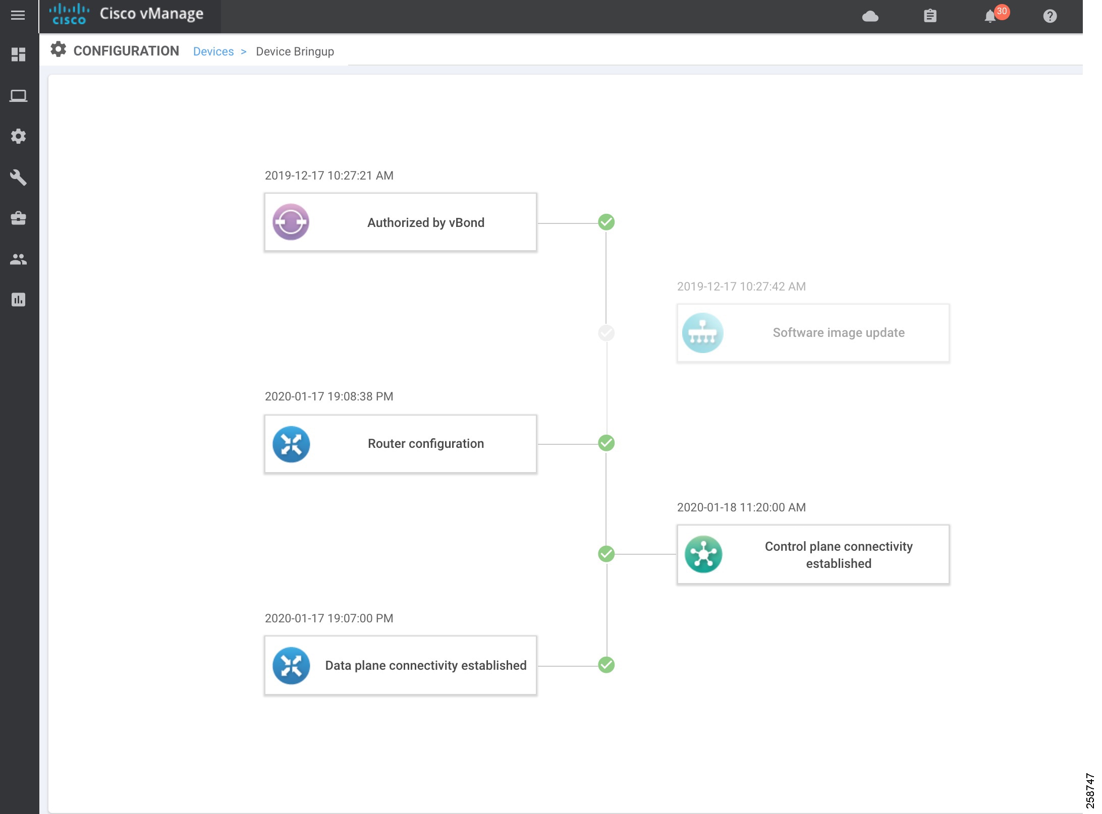
To check device onboarding status, go to Configuration > Devices. Click on more actions (…) at the end of the row and choose Device Bring up to see status of onboarding process. All stages should be passed with a green check mark. The only exception is the Software Image Update that may be grayed out. If there are any issues or the device is not found on the device list use this troubleshooting section.
Device is Not Authorized by vBond
■![]() Check the device is in the staging or valid state. Go to Configuration > Certificates and confirm the status of the device. If device is not in the list, make sure is added on PNP Connect portal and imported into vManage. If device is in invalid state, change to Valid or Staging and then click Send to Controllers at the top of the page.
Check the device is in the staging or valid state. Go to Configuration > Certificates and confirm the status of the device. If device is not in the list, make sure is added on PNP Connect portal and imported into vManage. If device is in invalid state, change to Valid or Staging and then click Send to Controllers at the top of the page.
■![]() Make sure the device is associated to a template on vManage. Go to Configuration > Devices. Click more actions (…) at the end of the row and choose Template Log. If logs show “No logs available”, associate to a template by following the Attach Device to Template section.
Make sure the device is associated to a template on vManage. Go to Configuration > Devices. Click more actions (…) at the end of the row and choose Template Log. If logs show “No logs available”, associate to a template by following the Attach Device to Template section.
■![]() If using PnP make sure the device got its IP configuration using DHCP, and check that the device is able to reach devicehelper.cisco.com. If the device is not getting an IP address, check physical connectivity and contact the service provider. If using cellular interfaces refer to Troubleshooting LTE Connectivity.
If using PnP make sure the device got its IP configuration using DHCP, and check that the device is able to reach devicehelper.cisco.com. If the device is not getting an IP address, check physical connectivity and contact the service provider. If using cellular interfaces refer to Troubleshooting LTE Connectivity.
■![]() The following is expected in the logs when doing PnP:
The following is expected in the logs when doing PnP:
■![]() Successful communication with the PnP server is shown on PnP Connect portal on the Devices tab as shown in the image below. The device Status column will show Redirect Successful instead of Pending Redirection. Click the Show Log link for more information, it will show timestamps, if the device contacted the server, and authentication results.
Successful communication with the PnP server is shown on PnP Connect portal on the Devices tab as shown in the image below. The device Status column will show Redirect Successful instead of Pending Redirection. Click the Show Log link for more information, it will show timestamps, if the device contacted the server, and authentication results.
Figure 32 PnP Connect Device Redirected

■![]() If device is onboarded using bootstrap, PnP Connect portal does not show any updates. Instead check if the configuration was loaded to the device with the show sdwan running-config command. If the configuration is not present, check that the configuration file ciscosdwan.cfg is present on bootflash or the bootable USB as described in the Bootstrap section.
If device is onboarded using bootstrap, PnP Connect portal does not show any updates. Instead check if the configuration was loaded to the device with the show sdwan running-config command. If the configuration is not present, check that the configuration file ciscosdwan.cfg is present on bootflash or the bootable USB as described in the Bootstrap section.
■![]() If the device is successfully redirected in the case of PnP or has the right configuration in the case of bootstrap, confirm the device is able to reach vBond. If using a domain name instead of IP address, check that the DNS server IP address is configured on the VPN0 feature template attached to the device and reachable from the router.
If the device is successfully redirected in the case of PnP or has the right configuration in the case of bootstrap, confirm the device is able to reach vBond. If using a domain name instead of IP address, check that the DNS server IP address is configured on the VPN0 feature template attached to the device and reachable from the router.
■![]() The command show sdwan control connections shows control connections, and if the device is not authenticated by vBond, use the show sdwan control connection-history command to see attempts to connect with code for failure. Common errors are:
The command show sdwan control connections shows control connections, and if the device is not authenticated by vBond, use the show sdwan control connection-history command to see attempts to connect with code for failure. Common errors are:
–![]() DCONFAIL: DTLS Connection Failure. Check connectivity, firewall or NAT configuration
DCONFAIL: DTLS Connection Failure. Check connectivity, firewall or NAT configuration
–![]() CRTREJSER/BIDNTVRFD: Serial Number(s) Not Present.
CRTREJSER/BIDNTVRFD: Serial Number(s) Not Present.
–![]() The serial number is not present on the controllers for a given device, you will see that control connections fail.
The serial number is not present on the controllers for a given device, you will see that control connections fail.
–![]() VSCRTREV/CRTVERFL: Certificate Revoked/Invalidated
VSCRTREV/CRTVERFL: Certificate Revoked/Invalidated
–![]() In cases when the certificate is revoked on controllers or WAN Edge serial number is invalidated.
In cases when the certificate is revoked on controllers or WAN Edge serial number is invalidated.
–![]() For more information on control connections troubleshooting refer to
For more information on control connections troubleshooting refer to
https://www.cisco.com/c/en/us/support/docs/routers/sd-wan/214509-troubleshoot-control-connections.html
■![]() The command show sdwan control statistics shows if control packets are being transmitted and received. If packets are sent but not received check connectivity.
The command show sdwan control statistics shows if control packets are being transmitted and received. If packets are sent but not received check connectivity.
Router Configuration Failure
vManage was not able to push configuration to the device. Go to Configuration > Devices. Click more actions (…) at the end of the row and choose Template Log. There are also options to review the configuration by selecting Running Configuration (on device) or Local Configuration (on vManage).
The Status column on Configuration > Devices will show Out of Sync if the template is not attached successfully to device. It is possible to click the Out of Sync link to view configuration differences.
Figure 33 Device Out of Sync with Template

Control Plane Connectivity Not Established
Go to Monitor > Network and select the device. Select Control Connections from the left panel to view connectivity to vManage and vSmart. If connectivity is not established, use the ping command to check connectivity.
Data Plane Connectivity Not Established
Check that the device is not in staging mode by going to Configuration > Certificates. If device is in Staging mode, switch to Active and click Send to Controllers at the top of the page.
Refer to the following link for more tips on data plane connectivity: https://www.cisco.com/c/en/us/support/docs/routers/sd-wan/214510-troubleshoot-bidirectional-forwarding-de.html
Configuration Reset
Clearing the configuration of the router may be needed in order to restart the PnP process. To clear the SD-WAN configuration from a router take either of the following actions.
Troubleshooting LTE Connectivity
Make sure the following requirements are addressed:
■![]() If the signal is not good at the router, use the Cisco offered antenna accessories and extension cables to place the antenna away from router in a better coverage area.
If the signal is not good at the router, use the Cisco offered antenna accessories and extension cables to place the antenna away from router in a better coverage area.
■![]() You must have 4G LTE network coverage where your router is physically placed.
You must have 4G LTE network coverage where your router is physically placed.
■![]() You must subscribe to a service plan with a wireless service provider and obtain a Subscriber Identity Module (SIM) card. Only micro SIM is supported. The SIM cards are usually provided in an unlocked state so that it can be used without a Personal Identification Number (PIN). If the SIM is unlocked, it can be inserted into a 4G LTE-Advanced module and used without an authorization code.
You must subscribe to a service plan with a wireless service provider and obtain a Subscriber Identity Module (SIM) card. Only micro SIM is supported. The SIM cards are usually provided in an unlocked state so that it can be used without a Personal Identification Number (PIN). If the SIM is unlocked, it can be inserted into a 4G LTE-Advanced module and used without an authorization code.
■![]() You must install the SIM card before configuring the 4G LTE or router.
You must install the SIM card before configuring the 4G LTE or router.
■![]() Make sure APN is configured per provider instructions. The show cellular unit profile command shows information about the modem data profiles created and attached. The unit argument identifies the router slot, module slot, and port separated by slashes (i.e. 0/1/0).
Make sure APN is configured per provider instructions. The show cellular unit profile command shows information about the modem data profiles created and attached. The unit argument identifies the router slot, module slot, and port separated by slashes (i.e. 0/1/0).
Router# show cellular 0/1/0 profile
■![]() The show cellular unit network command displays information about the carrier network, cell site, and available service.
The show cellular unit network command displays information about the carrier network, cell site, and available service.
■![]() The show cellular unit radio command shows the radio signal strength.
The show cellular unit radio command shows the radio signal strength.
■![]() Note that cellular networks have higher latency compared to wired networks. Latency rates depend on the technology and carrier. Latency also depends on the signal conditions and can be higher because of network congestion.
Note that cellular networks have higher latency compared to wired networks. Latency rates depend on the technology and carrier. Latency also depends on the signal conditions and can be higher because of network congestion.
Device Management
Software Upgrade
When upgrading using vManage, you can upgrade using a code image that is directly loaded onto vManage or a remote vManage, and you can also upgrade using a code image located on a remote file server. In this procedure, software for any device is uploaded to the vManage software repository.
Uploading Images on vManage
1.![]() Go to Maintenance > Software Repository. The repository stores the image locally on vManage, a remote file server, or remote vManage.
Go to Maintenance > Software Repository. The repository stores the image locally on vManage, a remote file server, or remote vManage.
2.![]() Click Add New Software and choose vManage from the drop-down list.
Click Add New Software and choose vManage from the drop-down list.
3.![]() A dialog box will appear prompting you to drop an image file or browse for an image on the local computer.
A dialog box will appear prompting you to drop an image file or browse for an image on the local computer.
4.![]() Load the desired images and click the Upload button. A window will indicate that the images are being loaded to the vManage. Once completed, a message will indicate the images were uploaded successfully, and the version, software location (vManage), and available files will be added to the repository.
Load the desired images and click the Upload button. A window will indicate that the images are being loaded to the vManage. Once completed, a message will indicate the images were uploaded successfully, and the version, software location (vManage), and available files will be added to the repository.
Device Upgrade
1.![]() Confirm there is enough space on the device for an image download using the dir bootflash: command. Free space is shown at the bottom. Remove files if needed.
Confirm there is enough space on the device for an image download using the dir bootflash: command. Free space is shown at the bottom. Remove files if needed.
2.![]() Go to Maintenance > Software Upgrade to check the code versions under the Current Version column.
Go to Maintenance > Software Upgrade to check the code versions under the Current Version column.

3.![]() If an upgrade is needed, check the check boxes next to the routers you want to upgrade and click the Upgrade button. A dialog box will appear.
If an upgrade is needed, check the check boxes next to the routers you want to upgrade and click the Upgrade button. A dialog box will appear.
4.![]() Verify vManage is selected. Choose the new code version from the drop-down list.
Verify vManage is selected. Choose the new code version from the drop-down list.
5.![]() Check the Activate and Reboot check box and then click Upgrade. The device will retrieve the software, install it, and then reboot in order to activate it. Optionally you can leave the box unchecked and activate the image later.
Check the Activate and Reboot check box and then click Upgrade. The device will retrieve the software, install it, and then reboot in order to activate it. Optionally you can leave the box unchecked and activate the image later.
Warning : upgrade may fail if there is insufficient disk space (CSCvq13666). Check release notes for more information. Make sure you check disk space before starting the upgrade on the device.
Activate an Image
For images already installed but not activated follow the steps:
1.![]() Go to Maintenance > Software Upgrade to check the code versions under the Current Version column.
Go to Maintenance > Software Upgrade to check the code versions under the Current Version column.
2.![]() Check the check boxes next to the routers you want to activate and click Activate. A dialog box will appear.
Check the check boxes next to the routers you want to activate and click Activate. A dialog box will appear.
3.![]() If there is an image installed ready to activate it will show in the Version drop-down menu. Select the version and click Activate. The router will reboot with the new version.
If there is an image installed ready to activate it will show in the Version drop-down menu. Select the version and click Activate. The router will reboot with the new version.
Best Practices
■![]() Break up the routers into different upgrade groups. You can identify them with a tag in the device-groups field in the system template. Target a test site or multiple test sites and put those routers into the first upgrade group.
Break up the routers into different upgrade groups. You can identify them with a tag in the device-groups field in the system template. Target a test site or multiple test sites and put those routers into the first upgrade group.
■![]() In dual-router sites, put each router into a different upgrade group and do not upgrade both of them at the same time.
In dual-router sites, put each router into a different upgrade group and do not upgrade both of them at the same time.
■![]() All routers in an upgrade group can be upgraded in parallel (up to 32 WAN Edge routers), however, take into account the ability for vManage or a remote file server to be able to handle the concurrent file transfers to the routers.
All routers in an upgrade group can be upgraded in parallel (up to 32 WAN Edge routers), however, take into account the ability for vManage or a remote file server to be able to handle the concurrent file transfers to the routers.
■![]() Upgrade the first upgrade group and let the code run stable for a predetermined amount of time, then proceed to upgrade the additional upgrade groups.
Upgrade the first upgrade group and let the code run stable for a predetermined amount of time, then proceed to upgrade the additional upgrade groups.
■![]() To keep the disk from getting full, clean up older versions using vManage. To delete older versions, go to Maintenance > Software Upgrade, select the device you want to clear and select Delete Available Software. On the dialog box select the images you want to delete and then click Delete.
To keep the disk from getting full, clean up older versions using vManage. To delete older versions, go to Maintenance > Software Upgrade, select the device you want to clear and select Delete Available Software. On the dialog box select the images you want to delete and then click Delete.
Reboot a Device
Reboot a router by going into Maintenance > Device Reboot. Make sure you are on the WAN Edge tab. Select the device to reboot and click Reboot. Confirm the action on the pop out window.
Connect to the Device Terminal
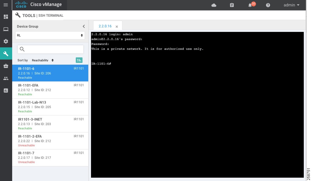
Go to Tools > SSH terminal. Choose the device you want to connect on the left panel. A terminal window to the device will be displayed. Provide device credentials.
Generate Admin Tech
Go to Tools > Operational Commands. Choose the router and click on more actions (…) at the end of the row. Click Admin Tech. Select the information you want to collect and click Generate. Wait until the file is generated and then click Download.
Monitor
Main Dashboard
Use the dashboard screen to monitor, at a glance, the overall health of the SD-WAN overlay network.
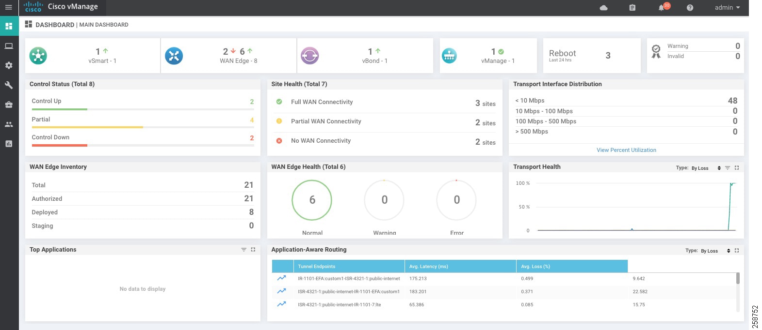
The top bar shows tasks and alarms on the system. The dashboard also displays all control connections from vManage to the vSmart controllers, WAN Edge routers, and vBond orchestrators in the overlay network as well as the status of the vManage NMSes in the network. You can click on the number or the Up or Down arrow to display a table with detailed information for each connection.
The dashboard displays the total number of reboots in the last 24 hours for all devices in the network. Click the Reboot pane for more information.
The Control Status pane displays whether vSmart and WAN Edge routers are connected to the required number of vSmart controllers. Each vSmart controller must connect to all other vSmart controllers in the network. Each WAN Edge router must connect to the configured maximum number of vSmart controllers. The Control Status pane shows three counts:
■![]() Control Up: Total number of devices with the required number of operational control plane connections to a vSmart controller.
Control Up: Total number of devices with the required number of operational control plane connections to a vSmart controller.
■![]() Partial: Total number of devices with some, but not all, operational control plane connections to vSmart controllers.
Partial: Total number of devices with some, but not all, operational control plane connections to vSmart controllers.
■![]() Control Down: Total number of devices with no control plane connection to a vSmart controller.
Control Down: Total number of devices with no control plane connection to a vSmart controller.
Click any row to display a table with device details.
The Site Health View pane displays the state of a site data connections. When a site has multiple WAN edge routers, this pane displays the state for the entire site, not for individual devices. The pane displays three states:
■![]() Full WAN Connectivity: Total number of sites where all BFD sessions on all WAN edge routers are in the up state.
Full WAN Connectivity: Total number of sites where all BFD sessions on all WAN edge routers are in the up state.
■![]() Partial WAN Connectivity: Total number of sites where a TLOC or a tunnel is in the down state. These sites still have limited data plane connectivity.
Partial WAN Connectivity: Total number of sites where a TLOC or a tunnel is in the down state. These sites still have limited data plane connectivity.
■![]() No WAN Connectivity: Total number of sites where all BFD sessions on all WAN edge are in the down state. These sites have no data plane connectivity.
No WAN Connectivity: Total number of sites where all BFD sessions on all WAN edge are in the down state. These sites have no data plane connectivity.
Click a row to display a pop-up window with detailed information on each site, node, or tunnel.
The Transport Interface Distribution pane displays interface usage in the last 24 hours for all WAN Edge interfaces in VPN 0. This includes all TLOC interfaces. Click a row to see details of interface usage.
The WAN Edge Inventory pane provides four counts:
■![]() Total: Total number of WAN Edge routers whose authorized serial number has been uploaded on the vManage server.
Total: Total number of WAN Edge routers whose authorized serial number has been uploaded on the vManage server.
■![]() Authorized: Total number of authorized WAN Edge routers in the overlay network. These are routers marked as Valid.
Authorized: Total number of authorized WAN Edge routers in the overlay network. These are routers marked as Valid.
■![]() Deployed: Total number of deployed WAN Edge routers. These are routers marked as Valid that are now operational in the network.
Deployed: Total number of deployed WAN Edge routers. These are routers marked as Valid that are now operational in the network.
■![]() Staging: Total number of WAN Edge routers in staging state.
Staging: Total number of WAN Edge routers in staging state.
Click any row to display a table with the hostname, system IP, site ID, and other details of each router.
The WAN Edge Health pane displays an aggregated view for each router state according to resource utilization and a count of how many WAN Edge routers are in that state
The Transport Health pane displays the aggregated average loss, latency, and jitter for all links and all combinations of colors. From the Type drop-down, select loss, latency, or jitter. Click the Expand icon to open the Transport Health window. This full-screen window displays a more detailed view of the same information.
The Application-Aware Routing pane displays the 10 worst tunnels over the last 24 hours based on criteria specified from the Type drop-down list, including loss, latency, and jitter.
Geography
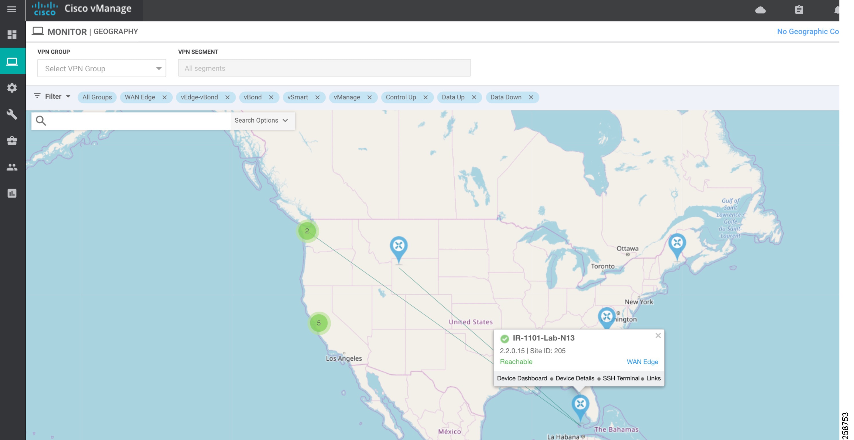
Use the Geography page (Monitor > Geography) to view information about the Cisco SD-WAN devices and links in the overlay management network. The Geography page provides a map displaying the geographic location of the Cisco SD-WAN devices. It is possible to filter by tag.
To choose the devices you want to display on the map use the Filter button, and the map is dynamically updated to reflect your selections. Also, as you make the device group, device type, and link selections, the tabs next to the Filter button are updated.
To display basic information for a device, hover over the device icon. A window displays the system IP address, hostname, site ID, device type, and device status.
By default, control and data connections are not displayed on the map. To see control and data connections for a device double-click the device icon to open a window with details about the device. Click Links.
■![]() An active control connection between two devices is displayed on the map as a thin blue line. Multiple active connections between devices are displayed by a bold blue line. A control connection that is down is displayed on the map as a dotted red line. Multiple control connections that are down are displayed by a bold dotted red line. If you hover over the line, the connection status (up or down) is shown.
An active control connection between two devices is displayed on the map as a thin blue line. Multiple active connections between devices are displayed by a bold blue line. A control connection that is down is displayed on the map as a dotted red line. Multiple control connections that are down are displayed by a bold dotted red line. If you hover over the line, the connection status (up or down) is shown.
■![]() An active data connection between two devices is displayed on the map as a thin green line. Multiple active data connections are displayed by a bold green line. A data connection that is down is displayed on the map as a dotted red line. Multiple data connections that are down are displayed by a bold dotted red line. If you hover over the line, the connection status (up or down) is shown.
An active data connection between two devices is displayed on the map as a thin green line. Multiple active data connections are displayed by a bold green line. A data connection that is down is displayed on the map as a dotted red line. Multiple data connections that are down are displayed by a bold dotted red line. If you hover over the line, the connection status (up or down) is shown.
■![]() An active consolidated control and data connection between two devices is displayed on the map as a thick gray line.
An active consolidated control and data connection between two devices is displayed on the map as a thick gray line.
Similarly, it is possible to double-click on the device to go to Device Dashboard, Device Details, or SSH terminal.
Tip : Device location and device groups are configured using System Feature Template.
Network
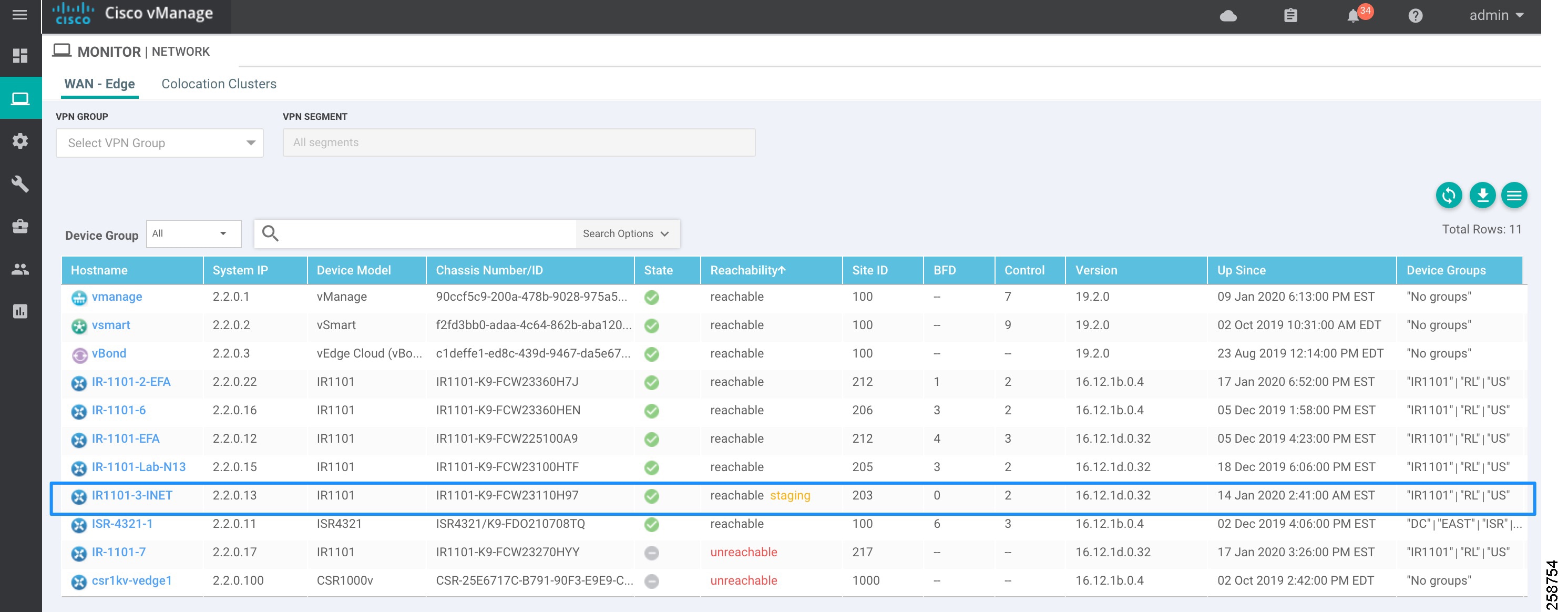
Use the Network page (Monitor > Network) to display a list of Cisco SD-WAN devices in the overlay network and to display detailed information about individual devices. The device list can be filtered by group, reachability, hostname, system IP address, site ID, and device model. Choose options from the Sort drop-down list or enter a string in the Search box.
The following image shows how to use the Network page to view devices in Staging state. Sort or filter by reachability. Note that this view also shows BFD and control connections. Devices in Staging will show control connections, but BFD will be 0. Information can be downloaded to a CSV file using the arrow at the top right of the table.
Figure 38 Monitor Network Reachability
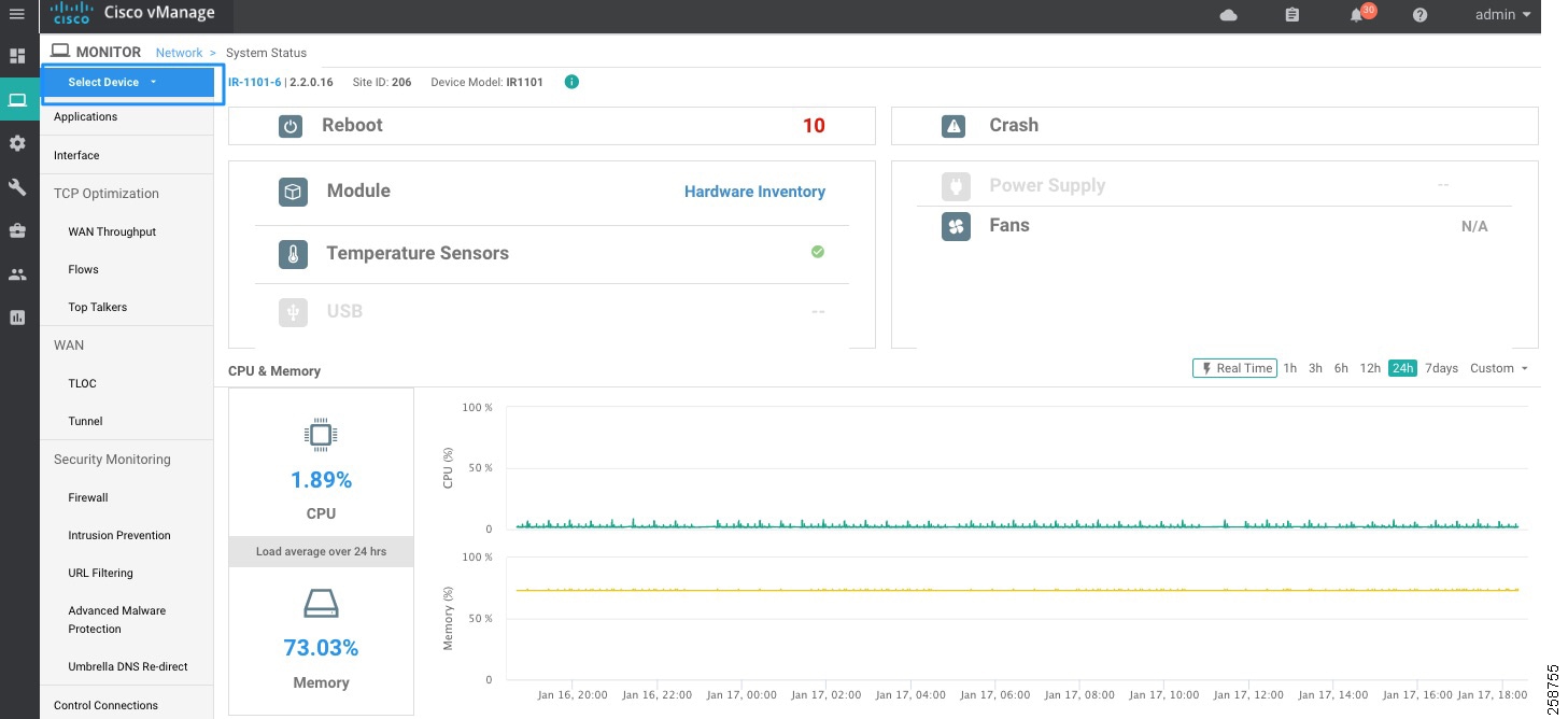
To display information about an individual device, click the device hostname. The left pane lists the information categories about the device. In the right pane, the System Status category is selected, which displays status information about the device.
To select a different device, either choose a device from the Select Device drop-down list located at the top of the left pane or click Network in the title bar and then click a device hostname.
System Status
To view system status for a device, go to Monitor > Network, then click a device hostname. The System Status page shows information such as CPU, memory, hardware inventory and number of times the device has rebooted.
WAN Information
Go to Monitor > Network and then click a device hostname.
■![]() WAN >TLOC on the left panel shows information about TLOC loss, latency, and jitter.
WAN >TLOC on the left panel shows information about TLOC loss, latency, and jitter.
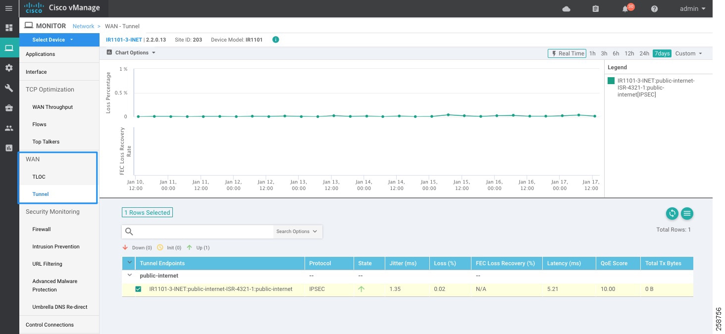
■![]() WAN > Tunnel on the left panel displays information about all data plane tunnels, you can easily see if you are sending or receiving packets for a particular tunnel. This can help you understand if packets are making it on each end, and isolate connectivity issues between the nodes.
WAN > Tunnel on the left panel displays information about all data plane tunnels, you can easily see if you are sending or receiving packets for a particular tunnel. This can help you understand if packets are making it on each end, and isolate connectivity issues between the nodes.
Figure 40 Monitor Device WAN Information
Control Connections
Go to Monitor > Network and click a device hostname, then choose Control Connections on the left panel. It shows the expected and actual number of connections and the control connections data in graphical and tabular format.
Events
To view the number of critical, major, or minor events on a device go to Monitor > Network and click a device hostname, then choose Events on the left panel. It shows a list of the events and a histogram.
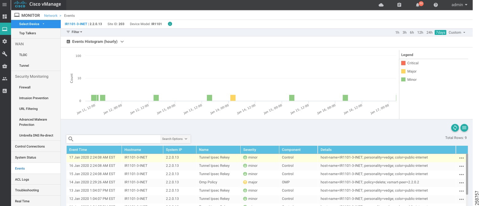
Tip : Events can be useful to troubleshoot a device that went offline. Choose Events from the left panel to display events from the device before it went down, such as bfd-state-change, omp-state-change, or control-connection-state-change.
Alarms
Use the Alarms (Monitor > Alarms) page to display detailed information about alarms generated by controllers and routers in the overlay network.
To set filters for searching alarms generated by one or more Cisco SD-WAN devices click the Filter drop-down menu. You can filter by severity, status, alarm name, severity and impacted entity. To view detailed information about any alarm, click the table row and click the More Actions icon (…) to the right of the row, then choose Alarm Details. The Alarms Details window opens, displaying the possible cause of the alarm, impacted entities, and other details.
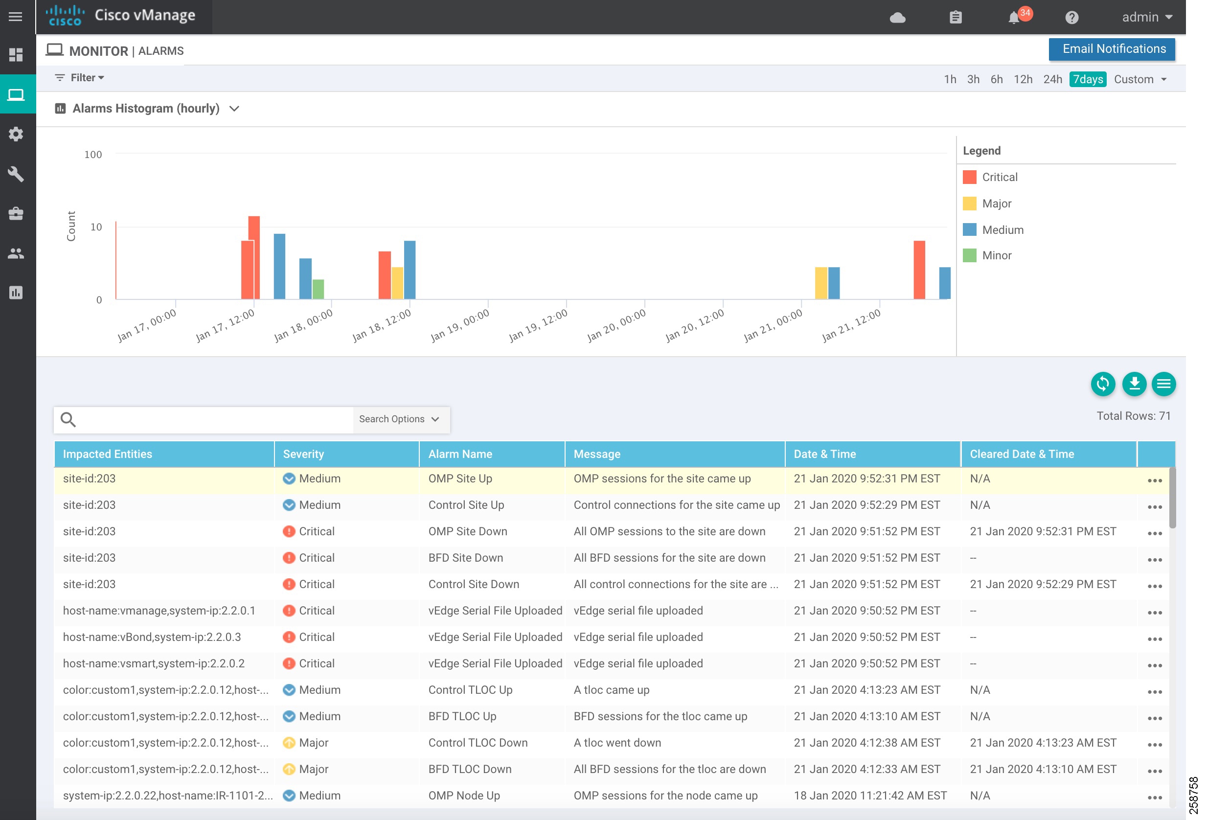
The software generates alarms when a state or condition changes, such as when a software component starts, transitions from down to up, or transitions from up to down. Refer to https://www.cisco.com/c/en/us/td/docs/routers/sdwan/configuration/Monitor-And-Maintain/monitor-maintain-book/monitor.html#c_Alarms_12333.xml for available alarms.
Troubleshooting
You can troubleshoot connectivity or traffic health for all devices in the overlay network. Go to Monitor > Network, click a device hostname, then choose Troubleshooting on the left panel. Some troubleshooting features are grayed out because they do not apply to IOS XE SD-WAN routers in this release.
■![]() Device Bring up is used to verify the status of device onboarding up as explained in Device Onboarding Troubleshooting.
Device Bring up is used to verify the status of device onboarding up as explained in Device Onboarding Troubleshooting.
■![]() Control Connections (Live View) shows Control Connections in Real Time. This view not only shows actual connections but detail on expected connections color and current status.
Control Connections (Live View) shows Control Connections in Real Time. This view not only shows actual connections but detail on expected connections color and current status.
■![]() Tunnel Health displays either loss, latency, or jitter in graphical format for all tunnels between the two devices in each direction.
Tunnel Health displays either loss, latency, or jitter in graphical format for all tunnels between the two devices in each direction.
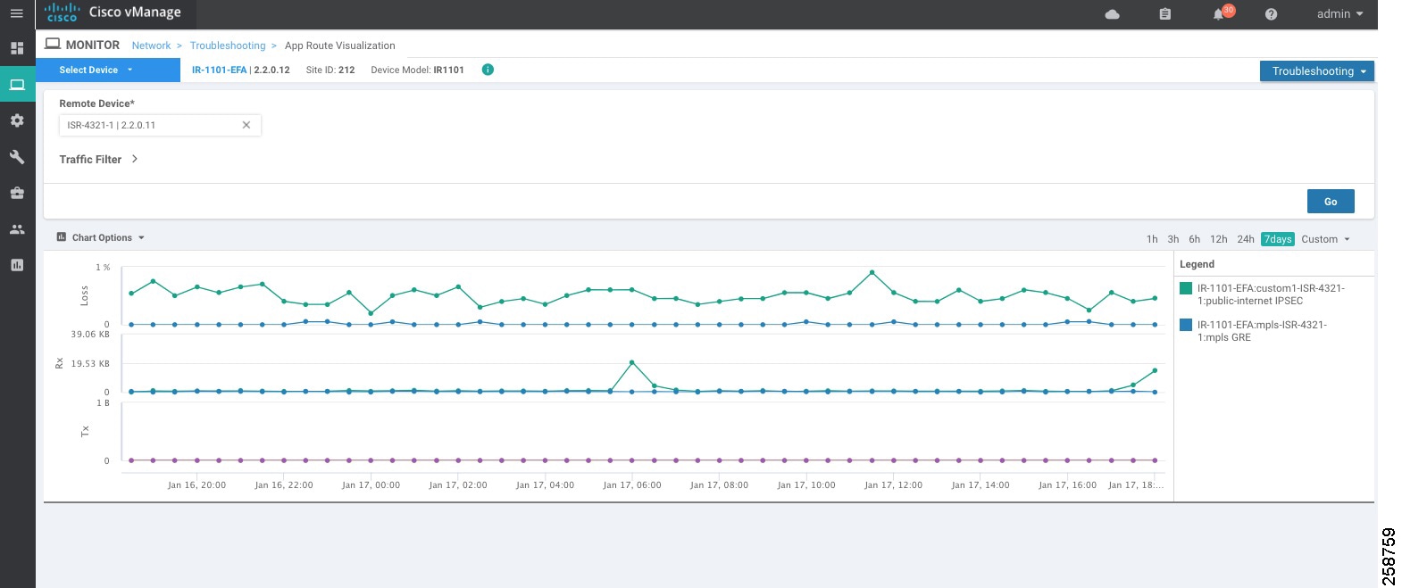
■![]() App route visualization is useful to check application-aware routing traffic from the source device to the destination device
App route visualization is useful to check application-aware routing traffic from the source device to the destination device
Figure 43 App Route Visualization
Real Time
To see device information in real time, go to Monitor > Network, click a device hostname, then choose Real Time. You will see the Device Options drop-down list located directly under the device name, from which you can choose a feature-specific operational command to display real-time device information for the selected command. The commands in the drop-down are listed alphabetically. The commands available vary depending on the device selected. When you first choose Real Time, the System Information command is selected, and real-time system information about the device is displayed in tabular format. For some commands, you can add filters to speed up the display of information.
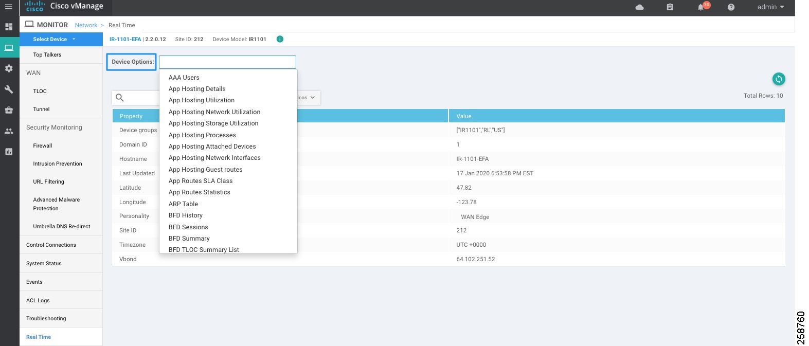
Some useful options are included in the table that follows.
BFD commands are useful to troubleshoot data plane connectivity. If BFD tunnels are flapping or down, then there may be packet loss, latency, or NAT issues. You can check which tunnels are up and down with the show bfd sessions and show bfd history commands. If too many BFD packets are dropped, the tunnel will go down.
OMP commands are useful to troubleshoot centralized control policy and tunnel preferences.
Additional Command Line Interface Commands
You can use SSH connection from vManage to run any CLI command. Some useful commands are described in the following sections.
Check Connectivity
Use the ping and traceroute commands to check connectivity. Make sure you are pinging from the right VPN; VPN 0 is default. Use VRF keyword to select VPN.
Check Template Attachment
If a template is not attaching, or if the configuration of the device is not changing, you can check the status of the template with the show sdwan system command. It will show vManage: true, Commit Pending: false and display configuration template name when template is attached successfully.
Check QoS Scheduler
Use the show policy-map interface int command to check stats for scheduler on the WAN interface. It will display the service policy name and statistics for rate and packets.
Check if Tunnel Meets SLA
Display statistics about jitter, loss, and latency and other interface characteristics for all operational data plane tunnels using the show sdwan app-route stats command. Sla-class-index line in the output displays SLA classes for which the tunnel meets SLA criteria.
Check Policy from vSmart
Display a centralized data policy, an application-aware policy, or a cflowd policy that a vSmart controller has pushed to the router with the command show sdwan policy from-vsmart.
Caveats and Limitations
■![]() Although profiles can be created, modified and deleted, current versions of vManage do not allow you to select the default profiles. If you need to use customized profiles (for example, Access Point Name (APN) in mobile networks), you must overwrite the selected default profile as explained in 4G LTE Configuration.
Although profiles can be created, modified and deleted, current versions of vManage do not allow you to select the default profiles. If you need to use customized profiles (for example, Access Point Name (APN) in mobile networks), you must overwrite the selected default profile as explained in 4G LTE Configuration.
■![]() The rollback feature does not support restoring changes to default APN configuration. If there is not an APN profile explicitly provisioned with a feature template before applying a template that overwrites the APN and control connection is lost due to that change, the rollback feature will not restore default APN configuration.
The rollback feature does not support restoring changes to default APN configuration. If there is not an APN profile explicitly provisioned with a feature template before applying a template that overwrites the APN and control connection is lost due to that change, the rollback feature will not restore default APN configuration.
■![]() Dual SIM cards with different APNs is not possible when using customized profiles due to a current vManage limitation. Using vManage version 19.2 (and older) it is not possible to associate a specific APN per slot using feature templates. Because of that any customization applied to a cellular unit will apply to all SIM slots on the module.
Dual SIM cards with different APNs is not possible when using customized profiles due to a current vManage limitation. Using vManage version 19.2 (and older) it is not possible to associate a specific APN per slot using feature templates. Because of that any customization applied to a cellular unit will apply to all SIM slots on the module.
■![]() An upgrade may fail if there is insufficient disk space (CSCvq13666). Check release notes for more information. Make sure you check disk space before starting the upgrade on the device.
An upgrade may fail if there is insufficient disk space (CSCvq13666). Check release notes for more information. Make sure you check disk space before starting the upgrade on the device.
 Feedback