Layer-4 to Layer-7 Services

Overview

Layer-4 through Layer-7 services support(s) end-to-end communication between a source and destination application. Layer 4-7 services are independent of the underlying network and provide services by enabling applications of load balancing, WAN acceleration and security appliances.

Cisco OpenStack Nexus Fabric Enabler (NFE) is a software that binds the generic OpenStack functionality with Nexus Fabric to provide the integrated and seamless cloud solution. The Enabler software consists of Nexus Server, Nexus Agent, and open source LLDP/VDP. For more information on Cisco Nexus Fabric, see Cisco Nexus Fabric OpenStack Enabler Install Guide.

Neutron is an OpenStack project to provide ‘networking as a service’ between interface devices (for example, virtualized Network Interface Card, used by a VM as its network interface) managed by other OpenStack services (for example, Nova). For more information on Neutron and related plugins, see Neutron.

Tenant Edge-Firewall

In a fabric, the firewall will allow or deny traffic based on the policies defined by the edge device. It will be used to control the north to south traffic, from a client to a datacenter server. The firewall requires of symmetry for ingress and egress traffic, whether it is an active/stand-by or clustering. A firewall is always connected to a router through a fabric to scale the resources.

Edge firewall connects a tenant (VRF or outside fabric) to another network in the north south traffic direction. VRF stitching is supported between the firewall and the server VRF with a transit subnet for routing. Servers use the anycast gateway (ToR) as the default gateway.

  • Consider a client outside the fabric wants to access a server within tenant VLAN 40 in VRF-A or tenant VLAN 20 in VRF-B.

  • Create a transit VLAN 41 in VRF-A for stitching and similarly VLAN 21 in VRF-B.

  • Traffic from client reaches the router with the destination as VLAN 40 and the next hop is VLAN 101 (VRF-C).

  • The Firewall intelligence routes the traffic to the connected Leaf on the protected Inside VLAN 41.

  • The Service Leaf node (connected to the FW) routes the traffic over the fabric to the destination Leaf.

  • Reverse traffic from Server in VLAN 40 uses the anycast-gateway IP on connected Leaf as next-hop. Default route injected by the FW is used to route traffic back to the Service Leaf node, which then routes it out to VLAN 101 towards the external router.

LBaaS

OpenStack supports LBaaS (Loadbalancer-as-a-Service). A virtual or physical device like 'f5 BIG-IPs' (a global load balancing solution) virtual and physical load balancer can be inserted into Cisco Programmable Fabric, allowing VMs acting as real servers behind the load balancer’s Virtual IPs (VIP), hosting various applications. By attaching the LBaaS to the Cisco Programmable Fabric network via its leaf switch is automatically done via auto-configuration and DCNM load balancer service VRF and network templates.

LBaaS Integration

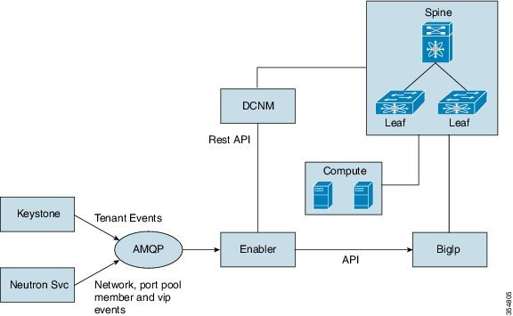
OpenStack enabler does not use Layer-3 agent or neutron routers. All the Layesr-3 functions are provided by spine-leaf fabric clusters. Neutron provides services where the vendors can plug-in their own implementations of APIs and optionally bring up a service agent, which can communicate with neutron server via Remote Procedure Call (RPC) queue.

To integrate LBaaS to the fabric enabler, the service is installed with the fabric enabler installation.

Cisco enabler will listen to VIP, pool, member resource change events from neutron and program BigIP with the event information. As of NFE 2.0, LBaaS v1 is supported with BigIp virtual or physical box.

LBaaS Configuration

In the neutron.conf file, service provider must point to an object in enabler [service_providers]

service_provider=LOADBALANCER:F5:dfa.server.services.loadbalance.lb_enabler.LBEnabler:default.

Following is the pre-configuration required on the F5 loadbalancer.
  • Configure the loadbalancer section within the fabric_enabler.ini file.

  • Configure the IP address and gateway on the loadbalancer.

  • Ensure loadbalancer is reachable via SSH and HTTPS.

  • Create the same user on the loadbalancer, as configured in the enabler_config.ini file.

  • Connect loadbalancer to the Nexus Fabric.

Following example shows the updated fabric_enabler.ini file.
lb_enabled = true
#lb_vrf_profile = vrf-common-universal-dynamic-LB-ES
lb_vrf_profile = vrf-common-evpn-dynamic-LB-ES
#lb_svc_net_profile=serviceNetworkUniversalDynamicRoutingLBProfile
lb_svc_net_profile=serviceNetworkDynamicRoutingLBEvpnProfile
#lb_svc_net = 199.199.1.0/24
#lb_svc_net_name_prefix=lbaasInternal
#comma separated (no space) list of big ip boxes
lb_mgmt_ip = 172.28.10.180
lb_user_name = admin
lb_user_password = cisco123
lb_f5_interface = N6k-73-75
[dcnm]
vlan_id_min = 670
vlan_id_max = 770

Note

Ensure to uncheck ‘enable dhcp’ while creating VIP network.


LBaas Agent

To configure loadbalance service via OpenStack horizon dashboard or via neutron cli, you must have LBaaS driver plugins. You have two options to do this:
  • Use OpenStack built in reference driver HAproxy and start its agent. The limitation is that as HAproxy is creating an internal interface with VIP address on br-int, you cannot use server subnet as VIP subnet because the traffic to VIP could be intercepted.

  • Write a no-op plugin driver and there is no LBaaS agent.

BIG-IP Support

The services enabler should be able to support multiple Load balancer devices in the fabric. To support this, a pool of Load balancer IP Addresses can be configured into the enabler configuration file as follows.
[lbaas] 
lb_mgmt_ip = 172.28.10.180, 172.28.10.181
lb_svc_net = 199.199.1.0/24, 188.188.1.0/24

For each project when a load balancer is allocated, a round robin algorithm can be used to pick one of the BIG-IP devices. Once selected, all the load balancers for that project are allocated to that BIG-IP device. Currently number of BIG-IP devices for a project will be limited to one. But multiple projects can use the same BIG-IP device. Fabric Enable is capable of restarting, to continue this support Project to BIG-IP module mapping will be stored in the SQL database via a new table.

When the fabric enabler service is started, the BIG-IP module of the enabler will establish connection with all the devices listed in the configuration file. Whenever a load balancer is created, enabler invokes the BIG-IP module with the following information.
[vlan, subnet IP, SubnetMask, Project Context ID, Project Context Name]

The BIG-IP module will pick one of the BIG-IPs and creates the required configuration. The Project context ID to BIG-IP device mapping is stored in the database in case the enabler restarts.

FWaaS

OpenStack supports FWaaS (Firewall-as-a-Service) that allows users to add perimeter firewall management to networking. FWaaS supports one firewall policy and logical firewall instance per project/tenant. With Cisco Programmable Fabric, each compute node is attached to a leaf node, which hosts the physical default gateways for all the VMs on the compute node.

A VM based Firewall such as CSR1000v can be inserted into the Cisco Programmable Fabric architecture and used as FWaaS in OpenStack. FWaaS insertion into the fabric will be automatically triggered via OpenStack FWaaS functionality, including configuring the firewall rules and policy. The leaf switch will be configured using its auto-configuration feature and VRF and network templates from DCNM for both its internal VRF/network and external VRF/network for a given tenant.

While the initial effort is based on a Cisco Adaptive Security Appliance (ASA) firewall, the same architecture can allow the insertion of VM based firewall device into the fabric as well. Since the firewall is actually acting as a router, OSPF will be transparently programed by the enabler when FWaaS is provisioned from OpenStack.


Note

Only physical ASA will be supported in first release. CSR1000v (virtual firewall) is not supported.


FWaaS Integration

OpenStack FWaaS adds perimeter firewall management to Networking. In OpenStack, routing is achieved through a router plugin. The router plugin uses the underlying Linux kernel routing implementation, to achieve routing. Every router created in OpenStack, has a Linux namespace created for it. If a VM in a subnet wants to communicate with another subnet, those subnets are added as interfaces to the router. In Juno release, every project is limited to one Firewall. The Firewall can have a policy, which can have multiple rules. The rules specify the classifier and actions. The firewall rules are applied to all the routers in the project and further to all the interfaces of a router.

OpenStack Firewall with Nexus Fabric

You can have firewall modules from different implementations with Nexus Fabric. When OpenStack is integrated with the Nexus Fabric, it is generally used as a tenant edge firewall. The following needs to be supported:
  • Physical or a virtual firewall appliance plug-in.

  • Configuration in OpenStack firewall must be translated to the appropriate firewall appliance’s configuration.

  • Nexus Fabric and the firewall appliance should have the appropriate configuration to support data path across the firewall appliance. This means:
    • Nexus Fabric should be able to redirect the traffic from a tenant, to the firewall module, if Tenant-Edge Firewall is configured for the tenant.

    • The firewall after performing the necessary operations, should have enough information to forward the frame to the fabric.

    • Similarly, the Nexus Fabric should forward the traffic from outside the tenant to the firewall module, which after performing the necessary operations should be able to forward the frame to the fabric, which can forward it back to the tenant.

The following section describes the packet flow for a tenant when a perimeter firewall is added through OpenStack in the presence of Physical ASA device acting as the firewall.

Firewall Manager

Firewall manager is responsible for acting on firewall related events from OpenStack such as policies, rules and Firewall creation/deletion and modification. The firewall and its associated rules and policies are decoded and stored per tenant. Based on the configuration, this module dynamically loads the Firewall Driver module. This module calls the Firewall Driver module when a firewall configuration gets added/deleted or modified.

For creating a Firewall, you need to create the rules, policy containing the rules and a Firewall containing the policy. You can create this in any order. For example, a Firewall can be created without any policy attached and later on, policies can be attached to the Firewall. Similarly, policies can be created without any rules attached at the beginning and then the policies can be updated with the rules. So, the Firewall module is responsible for caching the information and calling the modules to prepare the fabric or configure the Firewall device only after the complete firewall information is obtained.

Firewall Module

Firewall module is responsible for interacting with the actual device and doing the configuration. Depending on the appliance, the driver may use REST API or CLIs. Cisco Physical ASA and OpenStack Native firewall are supported.

Firewall module is responsible for the following:
  • Set-up the fabric when a firewall is created.

  • Clear the fabric configuration when the firewall is deleted.

  • Provide APIs on information about the fabric for other modules including the driver to use.

Firewall Configuration

Following are the steps to setup ASA.

Procedure


Step 1

Install Cisco ASA 5585-X. For more information, see Cisco ASA 5585-X Quick Start Guide.

The management interface can be set up by either using a console port or ADSM by connecting a PC to management interface. The ASA management IP address should be in the same management network as OpenStack Control and Compute nodes. You can either install a local ADSM client (mac) or run a web version.

Step 2

Ensure you run the recent version of Cisco ASA 5585-X.

Step 3

Install REST plugin.

Step 4

Acquire a Cisco ASA 5585-X license to support 100 security contexts.

Step 5

Enable Multiple Context Mode on ASA.

Step 6

Set up SSH access for Cisco ASA 5585-X. Ensure you can SSH to ASA. The management IP and credentials are required for OpenStack fabric enabler configuration (enabler_cfg.ini) file.

Step 7

Connect Cisco ASA 5585-X to leaf switch via two options:

  • Connect one ASA physical port to a leaf switch or

  • Connect two ASA physical ports to a pair of vPC-peer leaf switches (one to each). A port-channel shall be created on ASA for these two physical ports.


Example

Following example shows the configuration for the enabler software in the enabler_conf.ini file to configure the fabric and the device when a firewall is launched.
device = phy_asa
fw_mgmt_ip = '3.3.3.5'
#fw_username = [admin]
#fw_password = [cisco123]
#fw_interface_in = [Gi0/0]
#fw_interface_out = [Gi0/1]
#fw_auto_serv_nwk_create = True
# Currently only the MAX scheduling is supported
#sched_policy = 'max_sched'
#mob_domain_name = 'md0'
#fw_service_host_profile = 'serviceNetworkUniversalDynamicRoutingESProfile'
#fw_service_host_fwd_mode = 'proxy-gateway'
#fw_service_part_vrf_profile = 'vrf-common-universal-external-dynamic-ES'
#fw_service_ext_profile = 'externalNetworkUniversalDynamicRoutingESProfile'
#fw_service_ext_fwd_mode = 'anycast-gateway'
# It assumes a 24 subnet. In the example below, the first service IN network
# will have 100.100.2.x, and subsequent ones with have 100.100.3.x and so on.
#fw_service_in_ip_start = 100.100.2.0
#fw_service_in_ip_end = 100.100.20.0
#fw_service_out_ip_start = 200.200.2.0
#fw_service_out_ip_end = 200.200.20.0
#fw_service_dummy_ip_subnet = '9.9.9.0/24'

[firewall]
# Firewall Default Parameters

ASA Firewall driver

The firewall physical driver is the software layer that handles firewall events from firewall manager and program firewalls accordingly. Each type of firewalls, both physical and virtual, requires its own physical driver.

Firewall physical driver uses the REST API to configure the Cisco ASA 5585-X.

Event Handling

The ASA physical driver handles the following OpenStack events from firewall manager:
  • Firewall creation

  • Firewall deletion

  • Add firewall

  • Modify firewall

  • Delete firewall

REST API support

The Cisco ASA 5585-X REST API supports only a set of basic features, such as access rules and interfaces, but it provides a special API to send any CLI command to ASA.

This special API can take single or multi-line CLI commands and will present the output of the CLI as the API response:
Post URL:
/api/cli
Post Request Payload/Content: 
{
“commands”: [“command-1”, “command-2”,..., “command-n”]
}
Response: 
{
“response”: [“command-1 response”, “command-2 response”,..., “command-n response”]
}

The ASA physical driver implements a wrapper function (asa_rest_send) around this API to send commands to ASA 5585.

ASA Configuration

The ASA physical driver settings (IP of management interface and login credentials) are saved in “fw_constants.py”. The enabler_conf.ini file must have the following configuration enabled to support native firewall.
fw_service_host_profile = serviceNetworkUniversalESChainLBESProfile
fw_service_part_vrf_profile = vrf-common-universal-external- dynamic-ES
fw_service_ext_profile = externalNetworkUniversalDynamicRoutingESProfilew
  • fw_service_host_profile is the profile for the IN service network created by firewall module in Cisco DCNM.

  • fw_service_part_vrf_profile is the profile of the OUT service partition created by firewall module in Cisco DCNM.

  • fw_service_ext_profile is the profile for the OUT service network created by firewall module in Cisco DCNM.

Limitation

  • Cisco ASA 5585-X can only support up to 100 security contexts with a proper license, the maximum number of tenants that an OpenStack deployment can support with one Cisco ASA 5585-X is up to 100.

  • 125 VRF with 1 OSPF is the max that has been tested on Cisco Nexus 6000. Cisco ASA 5585 can support up to 2 OSPF instances. Each ASA security context can have their own OSPF configuration.

OpenStack Native Firewall driver

The driver handles the firewall events from firewall manager and programs the firewall accordingly.

OpenStack firewall support is achieved using Linux IP table rules. For Layer-3 forwarding, OpenStack relies on Linux kernel Layer-3 stack and uses namespace to achieve tenant separation. Natively, when a firewall is created in OpenStack, the rules of the firewall are applied to all the interfaces of the router. Creation of a router and attaching the networks to a router is a separate operation. Integrating OpenStack native firewall to a standalone Cisco fabric is achieved as follows:
  • When a Firewall is created in OpenStack, the driver automatically creates a router and attaches the IN or OUT interfaces to the router.

  • Driver ensures auto-configuration for the two interfaces is done in the fabric to ensure traffic is forwarded to the interfaces.

  • Unlike the Physical ASA, the router namespace does not run any routing protocol like OSPF, hence the driver ensures that static routes are populated in the fabric through Cisco DCNM.

Event handling

The native OpenStack firewall driver handles the following OpenStack events from firewall manager:
  • Firewall creation

  • Firewall deletion

  • Modify firewall

Firewall Creation

Creates a firewall instance in OpenStack, the driver performs the following tasks.
  1. Creates an OpenStack router using OpenStack python APIs. Attach the IN and OUT subnets to the router.

  2. Programs Cisco DCNM to update profile's static IP address on OUT partition. Since there is no OSPF running between the router namespace and the switch, the routes should be statically configured.

  3. Programs the default gateway in router namespace to point to the OUT interface.

  4. Both the IN and OUT subnet interfaces of the router belong to different VRF or Segment. For the switch to forward traffic to the router namespace, auto-config should happen just like a regular VM and these router interfaces should be seen as a VSI in the switch.

Firewall Deletion

Deletes the firewall instance OpenStack, the driver performs the following tasks.
  1. Removes the OpenStack router.

  2. Sends a VM VNIC delete message to the enabler event queue with the right segmentation ID for both IN and OUT interfaces of the router namespace.

Modify Firewall

The driver does not act on this event since OpenStack internally programs the router namespace.

Deployment

Enabler minimal configuration

The enabler_conf.ini file must have the following configuration enabled to support native firewall.
fw_service_host_profile = 'serviceNetworkUniversalESChainLBESProfile '
fw_service_part_vrf_profile = 'vrf-common-universal-external-static'
fw_service_ext_profile = 'externalNetworkUniversalTfStaticRoutingESProfile'
  • fw_service_host_profile is the profile for the IN service network created by firewall module in Cisco DCNM.

  • fw_service_part_vrf_profile is the profile of the OUT service partition created by firewall module in Cisco DCNM.

  • fw_service_ext_profile is the profile for the OUT service network created by firewall module in Cisco DCNM.

Enabler Restart

When enabler restarts, it retrieves configuration or state information from DB (MySQL) to initialize. Since only the create or delete events are handled by the driver for native firewall, the restart functionality is minimal.

Limitation

  • For every router creation, OpenStack creates a namespace.

  • Firewall configurations are done inside the namespace. The router namespace exists only in the network node of OpenStack.

  • OpenStack also has HA for network nodes. This native firewall solution is not tested with HA or multiple network nodes. Since, all the OUT traffic needs to flow through a network node, there can be scalability issues when there is heavy traffic that needs firewall policies to be applied since the firewall is not distributed (if firewall ran as a VM instead of a namespace) and runs in the Linux kernel which can be slower than a custom build ASIC.