Border Provisioning Use Case in VXLAN BGP EVPN Fabrics - VRF Lite

External connectivity from data centers is a prime requirement. Virtual eXtensible Local Area Network (VXLAN) Border Gateway Protocol (BGP) Ethernet VPN (EVPN) based data center fabrics provide east-west connectivity by distributing IP-MAC reachability information among various devices within the fabric. While the EVPN Multi-Site feature provides inter site connectivity, the VRF Lite feature is used for connecting the fabric to an external Layer 3 domain. Tenants, typically represented by virtual routing and forwarding instances (VRFs) can procure external connectivity via special nodes called borders. In this way, tenant workloads in one data center fabric can have Layer 3 connectivity to hosts within the same VRF in other fabrics. This chapter describes LAN Fabric provisioning of the Nexus 9000-based border devices through the Cisco® Data Center Network Manager (DCNM) for the VRF Lite use case. This use case shows you how to extend a VRF to an external fabric. In DCNM, configuration parameters are enhanced as follows:

Configuration methods - You can configure VRF Lite through automatic configuration and through the DCNM GUI.

Supported destination devices - You can extend VRFs from a VXLAN fabric to Cisco Nexus and non-Nexus devices. A connected non-Cisco device can also be represented in the topology.

Prerequisites and Guidelines

Prerequisites

  • The VRF Lite feature requires Cisco Nexus 9000 Series NX-OS Release 7.0(3)I6(2) or later.

  • Familiarity with VXLAN BGP EVPN data center fabric architecture and top-down based LAN fabric provisioning through the DCNM.

  • Fully configured VXLAN BGP EVPN fabrics including underlay and overlay configurations on the various leaf and spine devices, external fabric configuration through DCNM, and relevant external fabric device configuration (edge routers, for example).

    • A VXLAN BGP EVPN fabric (and its connectivity to an external Layer 3 domain for north-south traffic flow) can be configured manually or using DCNM. This document explains the process to connect the fabric to an edge router (outside the fabric, towards the external fabric) through DCNM. So, you should know how to configure and deploy VXLAN BGP EVPN and external fabrics through DCNM. For more details, see the Control chapter in the Cisco DCNM LAN Fabric Configuration Guide, Release 11.2(1).

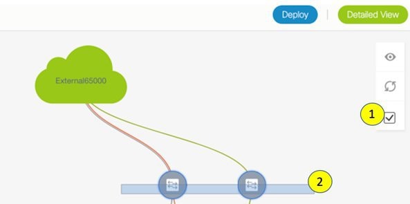
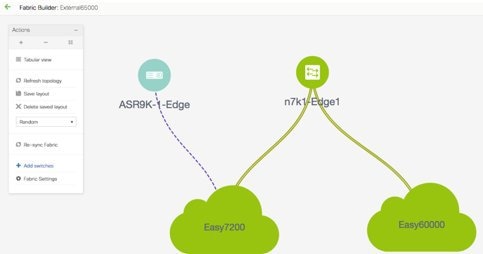
  • Ensure that the role of the designated border device is Border, Border Spine, Border Gateway, or Border Gateway Spine (a switch on which Multi-Site and VRF Lite functions co-exist). To verify, right-click the switch and click Set role. You can see that (current) is added to the current role of the switch. If the role is inappropriate for a border device, set the appropriate role.

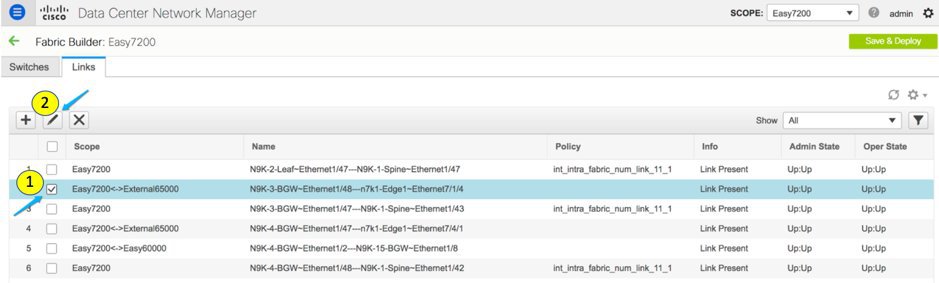
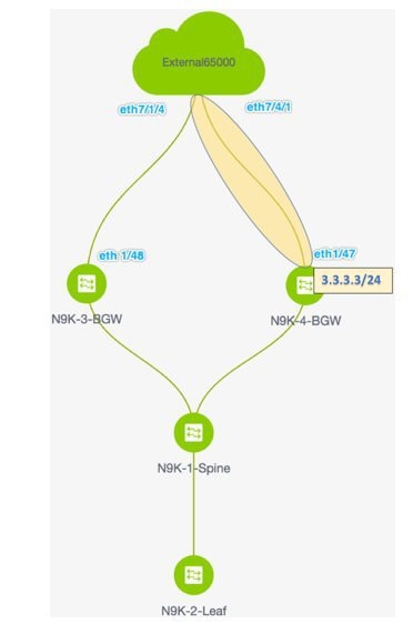
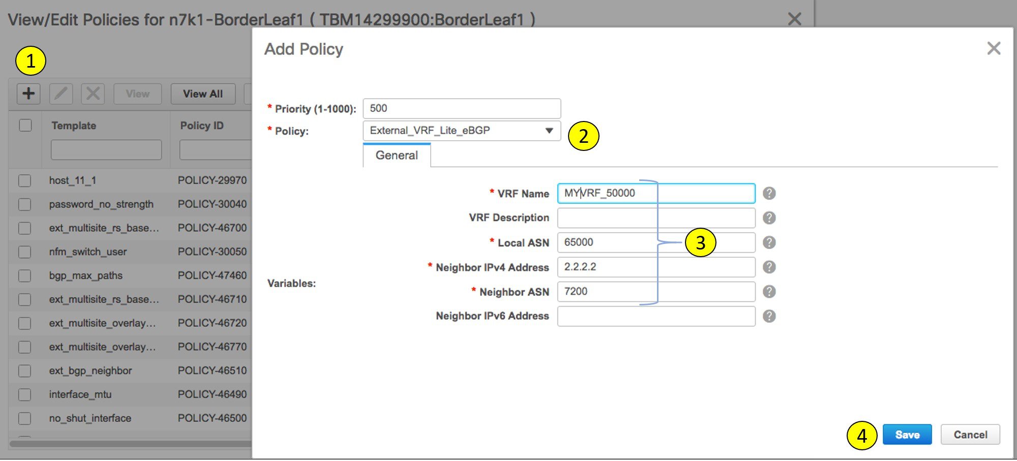
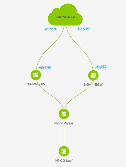
  • Create an external fabric. If you connect the VLXAN fabric border device to a Nexus 7000 Series switch (or other Nexus device) for external connectivity, add the Nexus 7000 series switch to the external fabric and set its role to Edge Router. In DCNM, you can import switches to an external fabric, and update selected configurations. For details, refer the Creating an External Fabric section in the Control chapter.

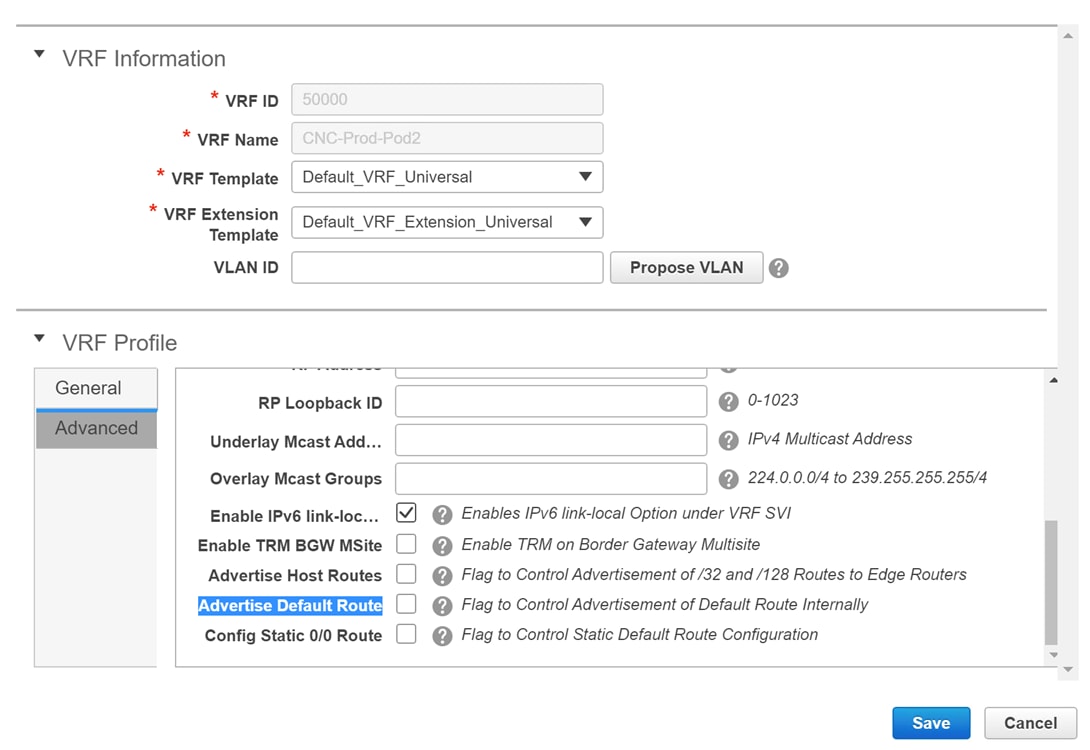
  • To allow inter-subnet communication between end hosts in different VXLAN fabrics, where the subnets are present in both fabrics, you must disable the Advertise Default Route feature for the associated VRF. This will result in /32 routes for hosts being seen in both fabrics. For example, Host1 (VNI 30000, VRF 50001) in Fabric1 can send traffic to Host2 (VNI 30001, VRF 50001) in Fabric2 only if the host route is present in both fabrics. When a subnet is present in only one fabric, then default route is sufficient for inter-subnet communication. Steps:

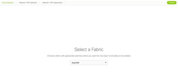
    1. Go to the fabric’s VRFs screen and select the VRF.

    2. Click the Edit option at the top left part of the screen.

    3. In the Edit VRF screen, click Advanced in the VRF Profile section.

    4. Clear the Advertise Default Route checkbox and click Save.

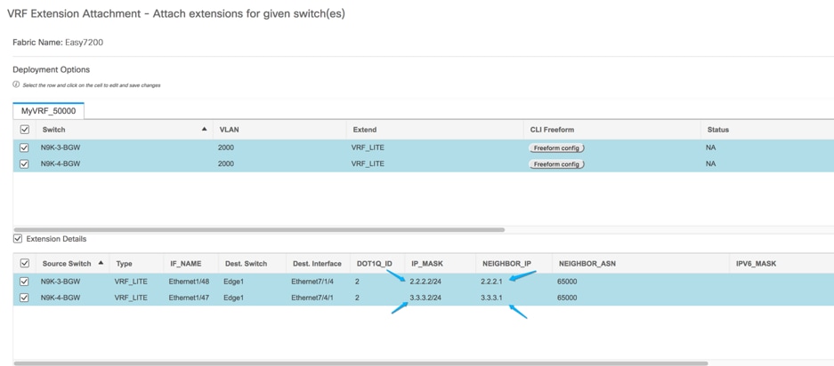
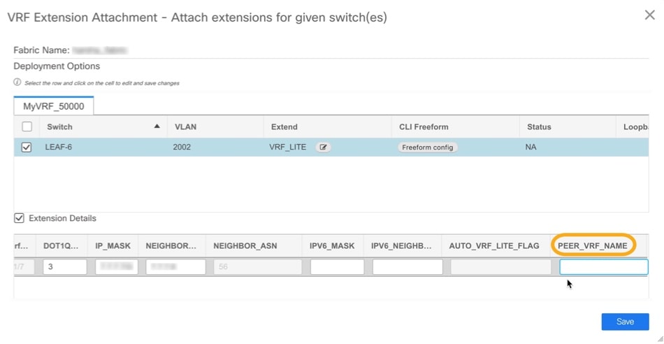
      The following options apply only when VRF Lite connectivity is enabled on the border devices. By default, following Cisco best practices, DCNM uses eBGP over sub-interfaces for VRF Lite, Option-A peering. In other words, for each VRF Lite Inter-fabric connection (IFC), there is a per VRF per peer eBGP peering session established over IPv4/IPv6 respectively from the border device to the edge/WAN router. As applicable to this VRF Lite peering, there are 3 fields:

      • Advertise Host Routes – By default, over the VRF Lite peering session, only non-host (/32 or /128) prefixes are advertised. But if host routes (/32 or /128) need to be enabled and advertised from the border device to the edge/WAN router, then the “Advertise Host Routes” check box can be enabled. Route-map does outbound filtering. By default, this check box is disabled.

      • Advertise Default Route – This field controls whether a network statement 0/0 will be enabled under the vrf. This in turn will advertise a 0/0 route in BGP. By default, this field is enabled. When the check box is enabled, this will ensure that a 0/0 route is advertised inside the fabric over EVPN Route-type 5 to the leafs thereby providing a default route out of the leafs toward the border devices.

      • Config Static 0/0 Route –The field controls whether a static 0/0 route to the edge/WAN router, should be configured under the VRF, on the border device. By default, this field is enabled. If WAN/edge routers are advertising a default route over the VRF Lite peering, to the border device in the fabric, then this field should be disabled. In addition, the “Advertise Default Route” field should also be disabled. This is because the 0/0 route advertised over eBGP will be sent over EVPN to the leafs without the need for any additional configuration. The clean iBGP EVPN separation inside the fabric with eBGP for external out-of-fabric peering, provides for this desired behavior.

      Note that all of the options listed are per fabric fields. Hence, in Multi-Site deployments with MSD, these fields can be controlled at a per member fabric level.

    5. Follow this procedure for all VRFs deployed on the VXLAN fabrics’ border devices connected through VRF Lite.


      Note

      If you create a new VRF, ensure that you clear the Advertise Default Route checkbox.


Note

For an explanation on the VRF Lite feature, see the Cisco Programmable Fabric with VXLAN BGP EVPN Configuration Guide document.


Guideline

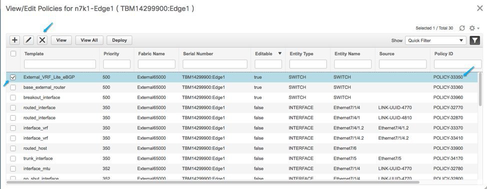
In a DCNM Release 10.4(2) setup where VRF-Lite IFCs are created, the required default prefix-lists or route-maps configs are added on the switch. When this DCNM Release 10.4(2) setup is upgraded to any of the DCNM 11.x releases, VRF-Lite related RPM configs might be saved as part of the switch_freeform policy.

The following route-map config is part of this switch_freeform:

route-map EXTCON-RMAP-FILTER-V6 deny 20
match ip address prefix-list host-route-v6

When this setup is upgraded from DCNM Release 11.x to 11.3(1), the route-map config is corrected with the following config:

route-map EXTCON-RMAP-FILTER-V6 deny 20
match ipv6 address prefix-list host-route-v6

Since RPM configs are saved in DCNM 11.x as switch_freeform, you need to manually delete the ip prefix-list match config in the switch_freeformpolicy so that ipv6 match config is successful on the switch.

Sample Scenarios

Scenarios explained in this document:

  • VRF Lite through the DCNM GUI – From a BGW device to a Nexus 7000 Series edge router.

  • VRF Lite through the DCNM GUI – From a BGW device to a non-Nexus device.

  • Automatic VRF Lite (IFC) Configuration.


Note

  • The sample scenarios are shown using a Border Gateway role but are equally applicable to the Border nodes as well.

  • Anything that applies to Border or Border Gateway roles also applies to Border Spine and Border Gateway Spine roles.


VRF Lite Through the DCNM GUI – From a BGW Device to a Nexus 7000 Series Edge Router

  • The topology displays the VXLAN BGP EVPN fabric Easy7200 connected to the external fabric External65000 (the cloud icon). The BGWs of the VXLAN fabric are connected to the edge router n7k1-Edge1 (not visible in the image) in the external fabric.

  • The BGWs are special devices that allow clear control and data plane segregation from the fabric domain to the external Layer 3 domain while allowing for policy enforcement points for any inter-fabric traffic. Network configurations for the VXLAN fabric are provisioned through DCNM. For external Layer 3 reachability from hosts connected to leaf switches within the fabric, border devices need to be provisioned with the appropriate VRF configuration. Multiple border devices in the fabric ensure redundancy in the case of failures as well as effective load distribution. This document shows you how to enable Layer 3 north-south traffic between the VXLAN fabric and the external fabric.

  • Before VRF Lite configuration, end hosts associated with a specific VRF can send traffic to each other, but only within the fabric. After VRF Lite configuration, end hosts can send traffic outside the VXLAN fabric, towards other (VXLAN or classic LAN) fabrics

Enabling the VRF Lite feature

For this example, we will enable connectivity between Easy7200 and External65000. The steps:

Step 1 - Deploy IFC prototypes on physical interfaces, on N9K-3-BGW and N9K-4-BGW.

Step 2 - Deploy the individual VRF extensions on the BGWs N9K-3-BGW and N9K-4-BGW.

Step 3 - Deploy VRF extensions on the edge router n7k1-Edge1.

The third step completes the configuration between Easy7200 and External65000.

Step 1 – Deploying IFC prototypes on physical interfaces on N9K-3-BGW and N9K-4-BGW

For VRF Lite configuration, you should enable eBGP peering between the fabric’s BGW interfaces and the edge router’s interfaces, through point-to-point connections. The BGW physical interfaces are:

  • eth 1/48 on N9K-3-BGW, towards eth 7/1/4 on n7k1-Edge1.

  • eth 1/47 on N9K-4-BGW, towards eth 7/4/1 on n7k1-Edge1.


Note

You can also enable VRF Lite in a back-to-back topology wherein Border/Border Gateways are directly connected to each other. VRF Lite can be enabled on physical Ethernet interface or layer 3 port-channel. Sub-interface over physical interface or layer 3 port-channel interface is created by DCNM at the VRF extension moment for each VRF lite link the VRF is extended over.


  1. Click Control > Fabric Builder. The Fabric Builder screen comes up.

  2. Click the Easy7200 box. The fabric topology comes up.

  3. Click Tabular view. The Switches | Links screen comes up.

    The Links tab lists fabric links. Each row either represents a link between two devices within Easy7200 or a link from a device in Easy7200 to an external fabric.


    Note

    An inter-fabric link is a physical connection between two Ethernet interfaces or a virtual connection (such as a fabric overlay between two loopback interfaces). When you add a physical connection between devices, the new link appears in the Links tab by default.


  4. Select the link checkbox (that represents the connection between eth 1/48 on N9K-3-BGW, towards eth 7/1/4 on n7k1-Edge1) and click the Edit icon at the top left part of the screen.

    The fields are:

    Scope – The source and destination fabrics are displayed. For an intra-fabric link, only one fabric name (Easy7200) is displayed since the source and destination interfaces are part of the same fabric. An inter-fabric link is displayed as Easy7200 <->External65000.

    Name – The name is formed with the following syntax:

    source device ~ source interface --- destination device ~ destination interface.

    So, the entry is N9K-4-BGW ~ Ethernet1/47 --- n7k1-Edge1 ~ Ethernet7/4/1.

    Policy – The policy used for creating VRF Lite, ext_fabric_setup_11_1 is displayed.

    Info – This displays the status of the link (Link Present, Neighbor Present, Neighbor Missing, etc).

    Admin State – This displays the administrative state of the link (Up, Down, etc).

    Oper State – This displays the operational state of the link (Up, Down, etc).

    The Link Management – Edit Link comes up.

    Some fields are explained:

    Link Sub-Type - By default, the VRF_LITE option is displayed.

    Link Template – The default template for a VRF Lite IFC, ext_fabric_setup_11_1, is displayed. The template enables the source and destination interfaces as Layer 3 interfaces, configures the no shutdown command, and sets their MTU to 9216.

    You can edit the ext_fabric_setup_11_1 template or create a new one with custom configurations.

    In the General tab, the BGP AS numbers of Easy7200 and External65000 are displayed. Fill in the other fields as explained.

    IP Address/Mask – Enter the IP address prefix to assign an IP address for the Ethernet 1/48 sub interfaces, the source interface of the IFC. A sub-interface is created for each VRF extended over this IFC, and a unique 802.1Q ID is assigned to it. The IP address/Mask entered here, along with the BGP Neighbor IP field (explained below) will be used as the default values for the sub-interface created at VRF extension and can be overwritten.

    For example, an 802.1Q ID of 2 is associated with subinterface Eth 1/48.2 for VRF 50000 traffic, and 802.1Q ID of 3 is associated with Eth 1/48.3 and VRF 50001, and so on.

    (The VRF extension deployment is explained in a subsequent section).

    The IP prefix is reserved with the DCNM resource manager. Ensure that you use a unique IP address prefix for each IFC you create in the topology.

    BGP Neighbor IP – Enter the IP address of the eBGP neighbor for each VRF extension deployed on this IFC, on the N9K-3_BGW end.

    Inter-fabric traffic from VRFs for an IFC will have the same source IP address (2.2.2.2/24) and destination IP address (2.2.2.1).

    The Advanced tab has been added in the Link Profile section.

    This tab contains the following fields:

    • Source Interface Description

    • Destination Interface Description

    • Source Interface Freeform Config

    • Destination Interface Freeform Config

  5. Click Save at the bottom right part of the screen.

    The Switches|Links screen comes up again. You can see that the IFC entry is updated with the VRF Lite policy template used for creating the IFC, ext_fabric_setup_11_1. A representation of the topology is shown below.

  6. Similarly, create an IFC from eth 1/47 on N9K-4-BGW towards eth 7/4/1 on n7k1-Edge1. An entry is seen in the Links screen. A representation of the topology is shown below.

  7. Click Save and Deploy at the top right part of the screen.

    The Links tab after executing Save and Deploy looks like this. The links on which IFC has deployed have the relevant policy configured in the Policy column.

  8. Go to the Scope drop down box at the top right part of the screen and choose External65000. The external fabric Links screen is displayed. You can see that the two IFCs created from Easy7200 to External65000 is displayed here.


    Note

    When you create an IFC or edit its setting in the VXLAN fabric, the corresponding entry is automatically created in the connected external fabric.


  9. Click Save and Deploy to save the IFCs creation on External65000.

    Base configurations – For VRF Lite to function, appropriate route maps and policies that apply to VRFs have to be deployed on the border devices N9K-3-BGW and N9K-4-BGW. You do not need to manually enable the base configurations. They are automatically deployed via a default template ext_base_border_vrflite_11_1.

    For a device with a Border Leaf or Border Spine role, the base configurations are deployed when you execute the Save and Deploy operation (available in the fabric topology screen [via the Fabric Builder screen > Fabric Box]) for the first time in a fabric.

    For a Border Gateway or Border Gateway Spine role, the base configurations are deployed when you deploy the first VRF Lite IFC on the device.

    You need to modify the ext_base_border_vrflite_11_1 template for specific needs before deployment or its policy should be deleted, template modified, and then deploy the template again. The configurations are noted in the Appendix section.

The first step in the VRF Lite configuration scenario, creating IFCs on the border devices and edge router, is complete. Next, the VRF extensions are deployed on the switches.

Step 1 - Deploy IFC prototypes on physical interfaces, on N9K-3-BGW and N9K-4-BGW.

Step 2 - Deploy the individual VRF extensions on the BGWs N9K-3-BGW and N9K-4-BGW.

Step 3 - Deploy VRF extensions on the edge router n7k1-Edge1.

The third step completes the configuration between Easy7200 and External65000.

Step 2 - Deploy the individual VRF extensions on the BGWs N9K-3-BGW and N9K-4-BGW

During the IFC creation process, base configurations are created, and IP addresses are reserved for the interfaces that transport the inter-fabric traffic on N9K-3-BGW and N9K-4-BGW. In this step, the VRF and VRF extension configuration is deployed on the interfaces.

To extend VRFs beyond the fabric, the VRFs should have been created and deployed on relevant fabric devices, except the border devices.

The steps are:

  1. Click Control > Networks and VRFs. The Networks & VRFs screen comes up.

  2. Click Continue. The Select a Fabric screen comes up.

  3. Select Easy7200 and click Continue at the top right part of the screen.

    The Networks screen comes up.

  4. Click VRFs at the top right part of the screen. The VRFs screen comes up.

  5. Select the VRF that you want to deploy (MyVRF_5000 in this case) and click Continue at the top right part of the screen.

    The Easy7200 fabric topology comes up.

  6. Select the Multi-Select checkbox at the top right part of the screen and drag the cursor across the BGWs on which you want to deploy the VRF and VRF extension configuration.

    The VRF Extension Attachment screen comes up. Each row represents a switch and each tab a VRF. Update settings for each tab as explained.

    In the Extend column, click on NONE and choose the VRF_LITE option from the drop down box. Do this for the second row too.

    Select the checkboxes in both rows.

    The Extension Details section comes up at the bottom of the screen. It displays the IFCs created on the selected switches, wherein each row represents an IFC.

    Select the IFC check boxes in both rows.

    After selecting the IFCs, the screen looks like this.

    DCNM will create one sub-interface for each VRF-LITE link above using the values in DOT1Q_IP, IP_MASK and NEIGHBOR_IP fields. The IP_MASK and NEIGHBOR_IP fields for each VRF LITE extension are filled with the IP Address/Mask and BGP Neighbor IP values entered in VRF LITE link creation. The IP_MASK and NEIGHBOR_IP fields, along with the DOT1Q_ID field, can be overwritten. IPV6_MASK and NEIGHBOR_IPV6 fields can be optionally entered if IPv6 eBGP session over the sub-interface is needed.

    Click Save at the bottom right part of the screen.

    The fabric topology screen comes up.

  7. Click the Preview option at the top right part of the screen to preview VRF and VRF extension configuration.

  8. Click Deploy at the top right part of the screen.

    At the bottom right part of the screen, the color codes that represent different stages of deployment are displayed. The color of the switch icons changes accordingly (Blue for Pending state, yellow for In Progress state when the provisioning is in progress, red for failure state, green when successfully deployed).

    When the switch icons turn green, it means that the VRFs are successfully deployed.

The second step in the VRF Lite configuration scenario, deploying VRF extensions on the border devices is complete. Next, the VRF extensions are deployed on the edge router n7k1-Edge1.

Step 1 - Deploy IFC prototypes on physical interfaces, on N9K-3-BGW and N9K-4-BGW.

Step 2 - Deploy the individual VRF extensions on the BGWs N9K-3-BGW and N9K-4-BGW.

Step 3 - Deploy VRF extensions on the edge router n7k1-Edge1.

The third step completes the configuration between Easy7200 and External65000.

Step 3 - Deploy VRF extensions on the edge router n7k1-Edge1

In order to extend VRFs on the edge router, keep a note of the following fields. VRF extension on the border device is on a per interface basis.

  • IP_MASK - This will become the neighbor address at the edge router end and mask will be the local mask on the edge router. This is derived from the IFC prototype created in the earlier step.

  • Easy Fabric ASN - This will become neighbor ASN from the edge router end. This is derived from the IFC prototype created in the earlier step.

  • Dot1Q tag - This will be same on the edge router. This is derived from the VRF extension table.

  • Neighbor ASN - This will become LOCAL ASN on the edge router. IFC prototype.

  • Neighbor IP - This will become Local IP for sub-interface on the edge router. IFC prototype.

  • Destination port - Will be local port on edge router upon which extension will be deployed.

You have deployed VRF extensions for MyVRF_50000 from the BGWs N9K-3-BGW and N9K-4-BGW. Now, you should deploy the VRF extensions on the other end of the links, on n7k1-Edge1. In DCNM, the CLI template used for this is External_VRF_Lite_eBGP.

eBGP configuration on the edge router

  1. In the External65000 fabric topology screen, click Tabular view.

    The Switches | Links screen comes up.

  2. Select the switch checkbox and click the View/Edit Policies button.

    The View/Edit Policies screen comes up.

  3. Click + at the top left part of the screen to add a policy, and fill in the Add Policy screen as shown in the image.

    You can use a user defined template too in the Policy field.


    Note

    Note the policy ID for this VRF extension. It is useful when deleting the policy to remove the extension, when applicable.


    This defines a policy from the edge router towards N9K-3-BGW.

  4. As per the earlier steps, create a policy for the VRF extension towards N9K-4-BGW. The Neighbor IPv4 Address field for the second extension is updated with 3.3.3.3.

Sub interface policy on Edge Router

  1. In the External65000 fabric topology screen, click Tabular view.

    The Switches | Links screen comes up.

  2. Select the switch checkbox and click the Manage Interfaces button.

    The Manage Interfaces screen comes up.

  3. As shown in the image, select the interface connected to the border device (in this case Eth7/1/4), and click + at the top left part of the screen. Then, fill the Add Interface screen from corresponding IFC and VRF extensions on the border device.

    The example shows a break out port on the Cisco Nexus 7000 Series switch. This breakout must be performed using the DCNM breakout policy (the template name is breakout_interface). If this is not done, the subinterface deletion is blocked by DCNM.

  4. Click Save to save the settings, and Deploy to deploy the settings onto the switch.

  5. As explained in the earlier steps, create another subinterface policy for the VRF extension towards N9K-4-BGW. The Subinterface IP field for the second extension is updated with 3.3.3.1.

The third step in the VRF Lite configuration scenario, deploying VRF extensions on the edge router N7k1-Edge1 is complete. This step completes the configuration between Easy7200 and External65000.

VRF Lite Through the DCNM GUI – From a BGW Device To a Non-Nexus Device

In this case, the non-Nexus device is an ASR 9000 Series router, ASR9K-1-Edge which is connected to the BGW N9K-3-BGW in the Easy7200 fabric. The router is not imported through DCNM nor discovered via CDP or LLDP. To represent the non-Nexus device, you must create an external fabric. Refer the Creating an External Fabric topic to know how to create an external fabric. For this example, the external fabric External65000 is created.

The device and connection are displayed in the DCNM topology after the IFC creation between ASR9K-1-Edge and N9K-3-BGW.


Note

A connected non-Cisco device can also be represented in the topology.


The topology:

The steps are:

Step 1 - Deploy an IFC prototype on the N9K-3-BGW physical interface that connects to ASR9K-1-Edge.

Step 2 - Deploy the individual VRF extensions on N9K-3-BGW.

This step completes the configuration between Easy7200 and the non-Nexus device.

Step 1 - Deploy an IFC prototype on the N9K-3-BGW physical interface that connects to ASR9K-1-Edge

For VRF Lite configuration, you should enable eBGP peering between the fabric’s BGW interface and the ASR9K-1-Edge interface, through a point-to-point link.

  1. Click Control > Fabric Builder. The Fabric Builder screen comes up.

  2. Click the rectangular box that represents the Easy7200 fabric. The fabric topology screen comes up.

  3. Click Tabular view. The Switches | Links screen comes up.

    The Links tab lists fabric links. Each row either represents a link between two devices within Easy7200 or a link from a device in Easy7200 to an external fabric.

  4. Click + to add a new link. The Link Management – Add Link screen comes up.

    Fill or choose the fields as noted:

    Link Type – Choose Inter-Fabric.

    Link Sub-TypeVRF_Lite is displayed by default.

    Link Template - By default, the ext_fabric_setup_11_1 template is populated.


    Note

    You can add, edit, or delete user-defined templates. See Template Library section in the Control chapter for more details.


    Source Fabric - Easy7200 is selected by default.

    Destination Fabric – Select External65000.

    Source Device and Source Interface - Choose the BGW and the interface that connects to the ASR device.

    Destination Device and Destination Interface— Destination device and interface do not appear in the drop down box. Type any string here that will help identify the device. This name appears in the external fabric topology screen in the Fabric builder screen.

    General tab in the Link Profile section.

    BGP Local ASN - In this field, the AS number of the source fabric Easy7200 is autopopulated.

    IP Address/Mask - Enter the IP address and mask that is used in the VRF Extension Sub-interfaces.

    BGP Neighbor IP - Enter the IP address that is used on the External box as local interface address for the VRF Extensions.

    BGP Neighbor ASN - In this field, the AS number of the external fabric External65000 is autopopulated since we selected it as the external fabric.

    After filling up the Add Link screen, it looks like this:

  5. Click Save at the bottom right part of the screen.

    The Switches|Links screen comes up again. You can see that the IFC entry is updated.

  6. Click Save and Deploy at the top right part of the screen.

    The links on which the IFC is deployed has the relevant policy (ext_fabric_setup_11_1) configured in the Policy column.

  7. Go to the Scope drop down box at the top right part of the screen and choose External65000. The external fabric Links screen is displayed. You can see that the IFC created from Easy7200 to the ASR device is displayed here.

  8. Click Save and Deploy.

The first step in the VRF Lite configuration scenario from a BGW to a non-Nexus device is complete. Next, the VRF extensions are deployed on the BGW towards the ASR device.

Step 2 - Deploy the individual VRF extensions on N9K-3-BGW

To extend VRFs beyond the fabric, the VRFs should have been created and deployed on relevant fabric devices, excepting the border devices.

  1. Click Control > Networks and VRFs. The Networks & VRFs screen comes up.

  2. Click Continue. The Select a Fabric screen comes up.

  3. Select Easy7200 and click Continue at the top right part of the screen.

    The Networks screen comes up.

  4. Click VRFs at the top right part of the screen. The VRFs screen comes up.

  5. Select the VRF that you want to deploy (MyVRF_5000 in this case) and click Continue at the top right part of the screen.

    The Easy7200 fabric topology comes up.

  6. Double-click the N9K-3-BGW icon on which you want to deploy the VRF and VRF extension configuration.

    The VRF Extension Attachment screen comes up. Each row represents a switch and each tab a VRF. Only one VRF is extended in this example.

    In the Extend column, click on NONE. A drop down box appears. Choose the VRF_LITE option, and click outside the row.

    Select the checkbox next to the switch.

    The Extension Details section comes up at the bottom of the screen. It displays the IFCs created on the selected switches, wherein each row represents an IFC.

    Select the IFC check box. After selecting the IFCs, the screen looks like this.

    Click Save at the bottom right part of the screen.

    The fabric topology screen comes up.

  7. Click the Preview option at the top right part of the screen to preview VRF and VRF extension configuration.

  8. Click Deploy at the top right part of the screen.

    At the bottom right part of the screen, the color codes that represent different stages of deployment are displayed. The color of the switch icons changes accordingly (Blue for Pending state, yellow for In Progress state when the provisioning is in progress, red for failure state, green when successfully deployed, and so on).

    When the switch icons turn green, it means that the VRF is successfully deployed.

The second step in the VRF Lite configuration scenario, deploying VRF extensions on the border device towards the non-Nexus ASR device is complete.

The device and connection will display in the Easy7200 and External65000 fabrics.

Automatic VRF Lite (IFC) Configuration

You can enable VRF Lite auto-configuration by changing the fabric settings of the VRF Lite Deployment field under the Resources tab from Manual to any of the auto-configuration settings.


Note

In the fabric topology screen within Fabric Builder, you can view only the individual fabric and the external fabric connected.


  • The topology displays VXLAN BGP EVPN fabrics Easy60000 (at the left) and Easy7200 (at the right) and external fabric External65000 (at the top). The border leaf of one VXLAN fabric is connected to the border leaf of the other through the edge router n7k1-Edge1 in the external fabric.

  • The border leafs are special devices that allow clear control and data plane segregation from the fabric to the external Layer 3 domain while allowing for policy enforcement points for any inter-fabric traffic. Multiple border devices in the fabric ensure redundancy in the case of failures and effective load distribution. This document shows you how to enable Layer 3 north-south traffic between the VXLAN fabrics and the external fabric.

  • Before VRF Lite configuration, end hosts associated with a specific VRF can send traffic to each other, but only within the fabric. After VRF Lite configuration, end hosts can send traffic across fabrics.

  • Network configurations for the VXLAN fabric are provisioned through DCNM.

    The template used for VRF Lite IFC auto configuration is ext_fabric_setup_11_1. You can edit the ext_fabric_setup_11_1 template or create a new one with custom configurations.

Automatic VRF Lite Creation Rules

  • Ensure that no user policy is enabled on the interface that connects to the edge router. If a policy exists, then the interface will not be configured.

  • Auto configuration is provided for the following cases:

    • Border role in the VXLAN fabric and Edge Router role in the connected external fabric device

    • Border Gateway role in the VXLAN fabric and Edge Router role in the connected external fabric device

    • Border role to another Border role directly

    Note that auto configuration is not provided between two BGWs.

    If you need a VRF Lite between any other roles, then you have to deploy it manually through the DCNM GUI.

  • To deploy configurations in the external fabric, ensure that the Fabric Monitor Mode check box is cleared in the external fabric settings of the External65000 fabric. When an external fabric is set to Fabric Monitor Mode Only, you cannot deploy configurations on its switches.

There are four modes available for VRF Lite IFC creation.

  1. Manual - Use the GUI to deploy the VRF Lite IFCs as shown in the earlier section.

  2. To External Only - Configure a VRF Lite IFC on each physical interface of a border leaf (Spine) device in the VXLAN fabric that is connected to a device with the Edge Router role in the external fabric .

  3. Back to Back Only - Configure VRF Lite IFCs between directly connected border leaf (Spine) device interfaces of different VXLAN fabrics.

  4. Both - Use this option to configure IFCs for the modes To External Only and Back to Back Only.


Note

DCI subnet is required, even if the VRF Lite mode is Manual. This helps with the DCNM resource handling.


The default mode in fabric settings is Manual Mode. In order to change the mode to any of the others, edit the fabric settings. Under the Resources Tab, modify the VRF Lite Deployment field to one of the above mentioned auto config modes. In this example, ToExternalOnly option is chosen.

VRF Lite Subnet IP Range: The IP address for VRF Lite IFC deployment is chosen from this range. The default value is 10.33.0.0/16. Best practice is to ensure that each fabric has its own unique range and distinct from any underlay range in order to avoid possible duplication. These addresses are reserved with the Resource Manager.

VRF Lite Subnet Mask: By default its set to /30 which is best practice for P2P links.

Similarly, update the settings for the Easy60000 fabric too.

  • Check the Auto Deploy Flag check box in the Link Management dialog box. Checking this check box enables VRF lite deployment, including VRF Lite sub-interface and BGP peering configuration, on both ends of the link for managed devices.

    This image is not available in preview/cisco.com

  • When you extend the VRF lite in a consecutive scenario, the VRF must be present in the peer fabric and the VRF name must be same. An error message appears, if the VRF is not present in the peer fabric and if you try to extend the VRF lite.

  • When you extend the VRF lite between an easy fabric and an external fabric, the VRF name can be same as the source fabric, default, or another VRF name. Enter the VRF name used in the external fabric in the PEER_VRF_NAME field. The child PTIs for the subinterface, the VRF creation and BGP peering on the external fabric has the non-empty source. Hence, the policies cannot be edited or deleted from the View/Edit policies window.

  • Enter the IP mask under the IP_Mask column as well to deploy VRF from topdown using symmetric VRF lite.

  • Deploy configurations in both the fabrics. Perform Save & Deploy on the external fabrics to deploy the configurations. The easy fabric configuration can be deployed either from the topdown VRFs page or from the Fabric Builder window.

Once the fields are set, execute the Save and Deploy option in the VXLAN and external fabrics.

Deleting VRF Lite IFCs

Before deleting the IFC, remove all VRF extensions enabled on the IFC. Else, an error message is reported.

  1. Go to the Links tab of the fabric.

  2. Select the links with VRF Lite policy configured and click the delete button.

  3. Click OK to confirm deletion.

  4. Execute the Save and Deploy option in the fabric to reset the VRF Lite policy.

Deleting VRF Extensions deployed in External Fabric

This is a two part process:

  1. Delete the sub interface created using interface TAB.


    Note

    Skip this step if the VRF extension is to a non-Nexus device.


  2. Delete the policy created for eBGP external connection.

Deleting the sub-interface

Navigate to the Control->Interfaces page as shown below, select the sub-interface(s) to be deleted and the click the delete button.

Deleting the eBGP policy

Navigate to fabric builder page and select the relevant external fabric (External65000 in this example). Select the device and using the second mouse button select view edit policy.

Select the row for the policy ID used in eBGP policy create. Click the “X” as shown below to delete the policy.

Issue a save and deploy in external fabric to deploy the policy change.

Deleting IFCs Created By Automatic VRF Lite creation

Editing and deleting IFCs are done through the Link tab in the VXLAN fabric. The extra consideration for auto configured IFCs is that, in order to prevent the regeneration of IFC on next save and deploy, the mode should be changed back to manual mode, or Save config should be done only on the relevant devices.

  • In a consecutive scenario, if you delete the VRF lite IFC on one of the fabrics, the VRF lite is deleted from the peer fabric as well.

  • When you want to delete a VRF lite between an easy fabric and an external fabric, delete the extension in the easy fabric using the top-down approach. The extension will be automatically deleted from the external fabric.

  • Deploy the configurations in both the fabrics.

Appendix

N9K-3-BGW Configurations

N9K-3-BGW (base border configurations) generated by template ext_base_border_vrflite_11_1


Note

switch(config)# refers to the global configuration mode. To access this mode, type the following on your switch: switch# configure terminal.

(config) # 
ip prefix-list default-route seq 5 permit 0.0.0.0/0 le 1
ip prefix-list host-route seq 5 permit 0.0.0.0/0 eq 32
route-map extcon-rmap-filter deny 10
    match ip address prefix-list default-route
route-map extcon-rmap-filter deny 20
    match ip address prefix-list host-route
route-map extcon-rmap-filter permit 1000
route-map extcon-rmap-filter-allow-host deny 10
    match ip address prefix-list default-route
route-map extcon-rmap-filter-allow-host permit 1000
ipv6 prefix-list default-route-v6 seq 5 permit 0::/0
ipv6 prefix-list host-route-v6 seq 5 permit 0::/0 eq 128
route-map extcon-rmap-filter-v6 deny 10
    match ipv6 address prefix-list default-route-v6
route-map extcon-rmap-filter-v6 deny 20
    match ip address prefix-list host-route-v6
route-map extcon-rmap-filter-v6 permit 1000
route-map extcon-rmap-filter-v6-allow-host deny 10
    match ipv6 address prefix-list default-route-v6
route-map extcon-rmap-filter-v6-allow-host permit 1000

N9K-3-BGW VRF extension configuration


(config) # 
configure profile MyVRF_50000
    vlan 2000
        vn-segment 50000
    interface vlan2000
        vrf member myvrf_50000
           ip forward
           ipv6 forward
           no ip redirects
           no ipv6 redirects
           mtu 9216
           no shutdown

(config) # 

vrf context myvrf_50000
    vni 50000
    rd auto
    address-family ipv4 unicast
        route-target both auto
        route-target both auto evpn

   ip route 0.0.0.0/0 2.2.2.1
   address-family ipv6 unicast
         route-target both auto
         route-target both auto evpn

router bgp 7200
    vrf myvrf_50000
        address-family ipv4 unicast
            advertise l2vpn evpn
            redistribute direct route-map fabric-rmap-redist-subnet
            maximum-paths ibgp 2
            network 0.0.0.0/0
        address-family ipv6 unicast
            advertise l2vpn evpn
            redistribute direct route-map fabric-rmap-redist-subnet
            maximum-paths ibgp 2
        neighbor 2.2.2.1 remote-as 65000
            address-family ipv4 unicast
                send-community both
                route-map extcon-rmap-filter out

(config) # 

interface ethernet1/48.2
    encapsulation dot1q 2
    vrf member myvrf_50000
    ip address 2.2.2.2/24
    no shutdown
interface nve1
    member vni 50000 associate-vrf
configure terminal
    apply profile MyVRF_50000