Endpoint Locator
The Endpoint Locator (EPL) feature allows real-time tracking of endpoints within a data center. The tracking includes tracing the network life history of an endpoint and getting insights into the trends that are associated with endpoint additions, removals, moves, and so on. An endpoint is anything with at least one IP address (IPv4 and\or IPv6) and MAC address. Starting from Cisco DCNM Release 11.3(1), the EPL feature is also capable of displaying MAC-Only endpoints. By default, MAC-Only endpoints are not displayed. An endpoint can be a virtual machine (VM), container, bare-metal server, service appliance and so on.
 Important |
|
EPL relies on BGP updates to track endpoint information. Hence, typically the DCNM needs to peer with the BGP Route-Reflector (RR) to get these updates. For this purpose, IP reachability from the DCNM to the RR is required. This can be achieved over in-band network connection to the DCNM eth2 interface.
Some key highlights of the Endpoint Locator are:
-
Support for dual-homed and dual-stacked (IPv4 + IPv6) endpoints
-
Support for up to two BGP Route Reflectors or Route Servers
-
Support real-time and historical search for all endpoints across various search filters such as VRF, Network, Layer-2 VNI, Layer-3 VNI, Switch, IP, MAC, port, VLAN, and so on.
-
Support for real-time and historical dashboards for insights such as endpoint lifetime, network, endpoint, VRF daily views, and operational heat map.
-
Support for iBGP and eBGP based VXLAN EVPN fabrics. From Release 11.2(1), the fabrics may be created as Easy Fabrics or External Fabrics. EPL can be enabled with an option to automatically configure the spine or RRs with the appropriate BGP configuration (new in DCNM 11.2).
-
Starting from Cisco DCNM Release 11.3(1), you can enable the EPL feature for upto 4 fabrics. This is supported only in clustered mode.
-
Starting from Cisco DCNM Release 11.3(1), EPL is supported on Multi-Site Domain (MSD).
-
Starting from Cisco DCNM Release 11.3(1), IPv6 underlay is supported.
-
Support for high availability
-
Support for endpoint data that is stored for up to 180 days, amounting to a maximum of 100 GB storage space.
-
Support for optional flush of the endpoint data in order to start afresh.
-
Supported scale: 50K unique endpoints per fabric. A maximum of 4 fabrics is supported. However, the maximum total number of endpoints across all fabrics should not exceed 100K.
For more information about EPL, refer to the following sections:
Configuring Endpoint Locator
The DCNM OVA or the ISO installation comes with three interfaces:
-
eth0 interface for external access
-
eth1 interface for fabric management (Out-of-band or OOB)
-
eth2 interface for in-band network connectivity
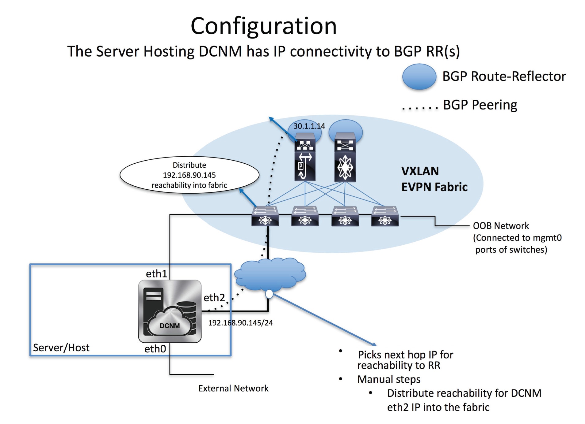
The eth1 interface provides reachability to the devices via the mgmt0 interface either Layer-2 or Layer-3 adjacent. This allows DCNM to manage and monitor these devices including POAP. EPL requires BGP peering between the DCNM and the Route-Reflector. Since the BGP process on Nexus devices typically runs on the default VRF, in-band IP connectivity from the DCNM to the fabric is required. For this purpose, the eth2 interface can be configured using the appmgr update network-properties command. Optionally, you can configure the eth2 interface during the Cisco DCNM installation.
If you need to modify the already configured in-band network (eth2 interface), run the appmgr update network-properties command again. Refer Editing Network Properties Post DCNM Installation to run the appmgr update network-properties command.
Note |
The setup of eth2 interface on the DCNM is a prerequisite of any application that requires the in-band connectivity to the devices within fabric. This includes EPL and Network Insights Resources (NIR). |
Note |
For configuring EPL in standalone mode, you must add a single neighbor to EPL. DCNM eth2 IP address is EPL IP. |
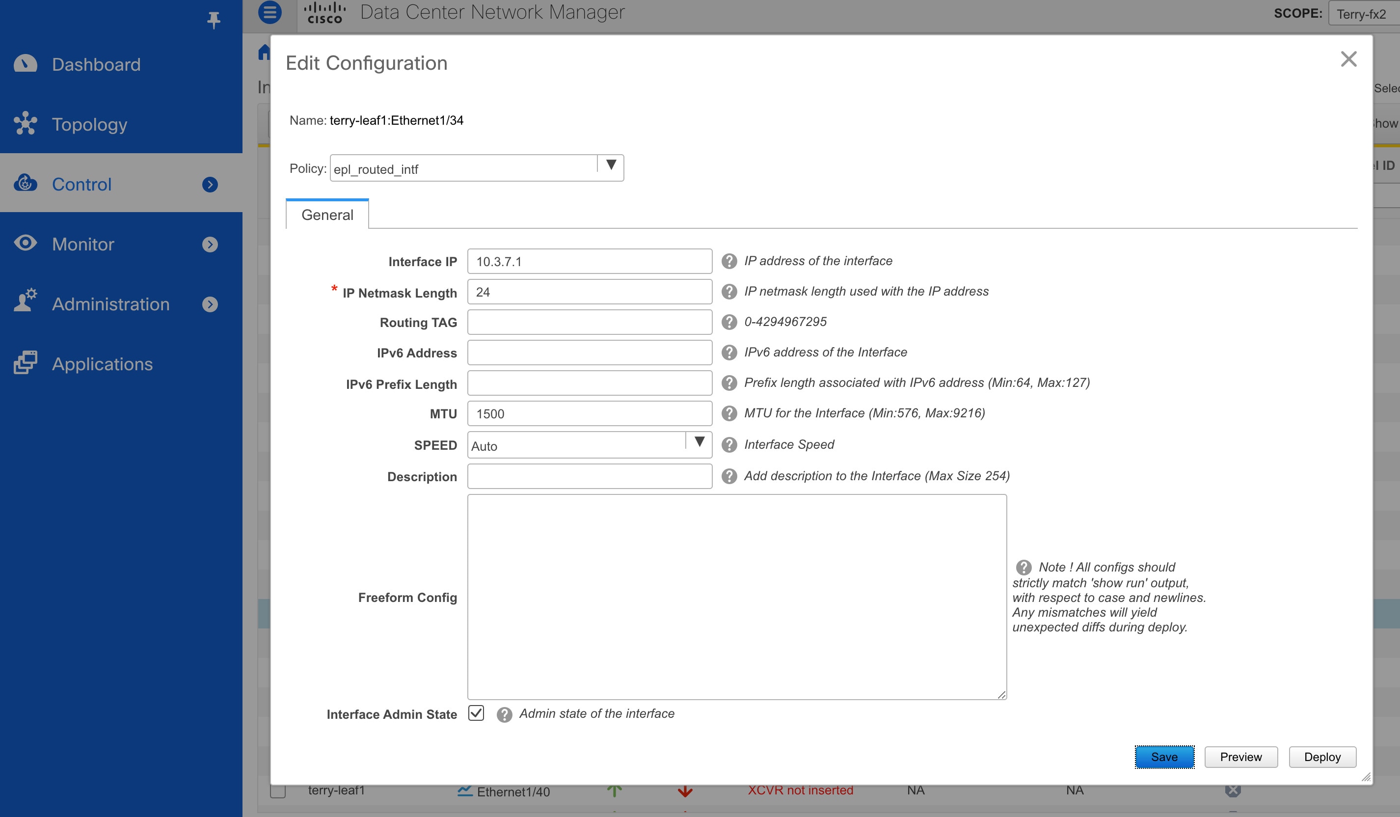
On the fabric side, for a standalone DCNM deployment, if the DCNM eth2 port is directly connected to one of the front-end interfaces on a leaf, then that interface can be configured using the epl_routed_intf template. An example scenario of how this can be done when IS-IS or OSPF is employed as the IGP in the fabric, is depicted below:
However, for redundancy purposes, it is always advisable to have the server on which the DCNM is installed to be dual-homed or dual-attached. With the OVA DCNM deployment, the server can be connected to the switches via a port-channel. This provides link-level redundancy. To also have node-level redundancy on the network side, the server may be attached to a vPC pair of Leaf switches. In this scenario, the switches must be configured such that the HSRP VIP serves as the default gateway of the eth2 interface on the DCNM. The following image depicts an example scenario configuration:

In this example, the server with the DCNM VM is dual-attached to a vPC pair of switches that are named Site2-Leaf2 and Site2-Leaf3 respectively. VLAN 596 associated with the IP subnet 10.3.7.0/24 is employed for in-band connectivity. You can configure the vPC host port toward the server using the interface vpc trunk host policy as shown is the following image:

For the HSRP configuration on Site2-Leaf2, the switch_freeform policy may be employed as shown in the following image:

You can deploy a similar configuration on Site2-Leaf3 while using IP address 10.3.7.2/24 for SVI 596. This establishes an in-band connectivity from the DCNM to the fabrics over the eth2 interface with the default gateway set to 10.3.7.1.
After you establish the in-band connectivity between the physical or virtual DCNM and the fabric, you can establish BGP peering.
During the EPL configuration, the route reflectors (RRs) are configured to accept DCNM as a BGP peer. During the same configuration, the DCNM is also configured by adding routes to the BGP loopback IP on the spines/RRs via the eth2 gateway.
Note |
Cisco DCNM queries the BGP RR to glean information for establishment of the peering, like ASN, RR, IP, and so on. |
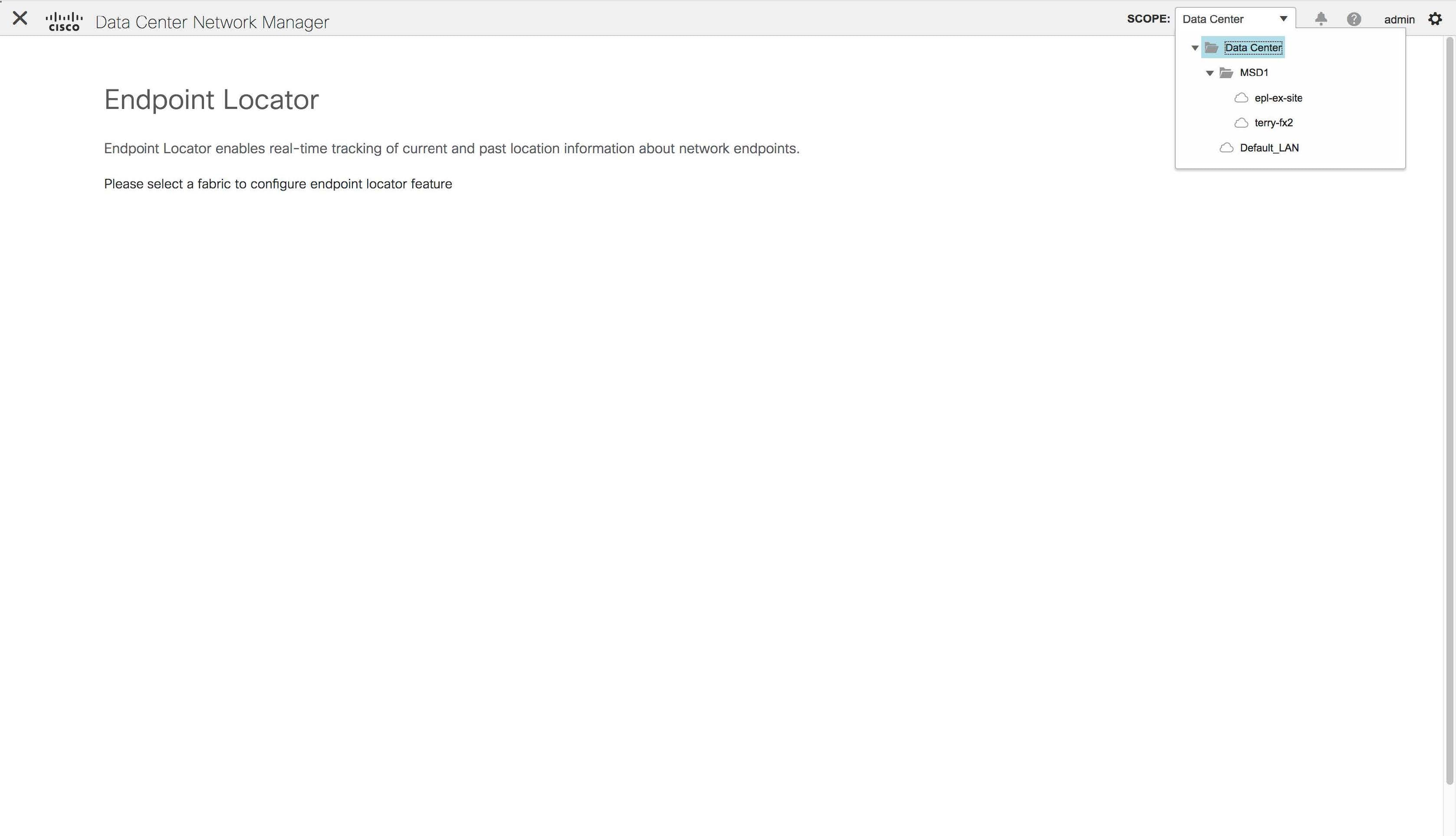
To configure Endpoint Locator from the Cisco DCNM Web UI, choose Control > Endpoint Locator > Configure. The Endpoint Locator window appears.
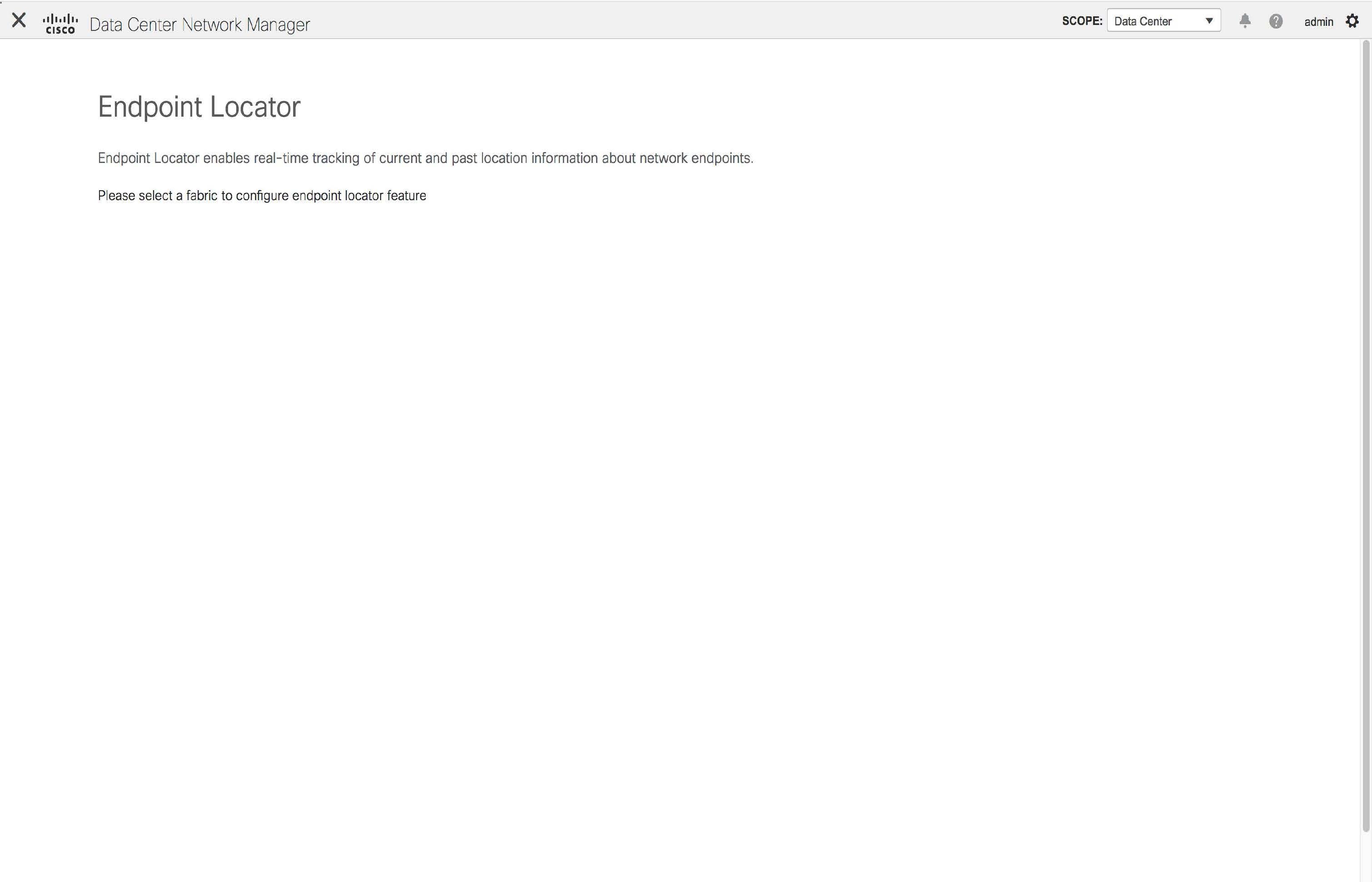
Select a fabric from the Scope drop-down list on which the endpoint locator feature should be enabled to track endpoint activity. You can enable EPL for one fabric at a time.
Select the switches on the fabric hosting the RRs from the drop-down list. Cisco DCNM will peer with the RRs.
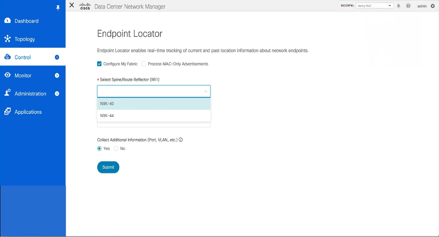
By default, the Configure My Fabric option is selected. This knob controls whether BGP configuration will be pushed to the selected spines/RRs as part of the enablement of the EPL feature. If the spine/RR needs to be configured manually with a custom policy for the EPL BGP neighborship, then this option should be unchecked. For external fabrics that are only monitored and not configured by DCNM, this option is greyed out as these fabrics are not configured by DCNM.
Select the Process MAC-Only Advertisements option to enable processing of MAC-Only advertisements while configuring the EPL feature.
Select Yes under Collect Additional Information to enable collection of additional information such as PORT, VLAN, VRF etc. while enabling the EPL feature. To gather additional information, NX-API must be supported and enabled on the switches, ToRs, and leafs. If the No option is selected, this information will not be collected and reported by EPL.
You can also watch the video that demonstrates how to configure EPL using Cisco DCNM. See Configuring Endpoint Locator.
Once the appropriate selections are made and various inputs have been reviewed, click Submit to enable EPL. If there are any errors while you enable EPL, the enable process aborts and the appropriate error message is displayed. Otherwise, EPL is successfully enabled.
When the Endpoint Locator feature is enabled, there are a number of steps that occur in the background. DCNM contacts the selected RRs and determines the ASN. It also determines the interface IP that is bound to the BGP process. Also, appropriate BGP neighbor statements are added on the RRs or spines in case of eBGP underlay, to get them ready to accept the BGP connection that will be initiated from the DCNM. For the native HA DCNM deployment, both the primary and secondary DCNM eth2 interface IPs will be added as BGP neighbors but only one of them will be active at any given time. Once EPL is successfully enabled, the user is automatically redirected to the EPL dashboard that depicts operational and exploratory insights into the endpoints that are present in the fabric.
Fore more information about the EPL dashboard, refer Monitoring Endpoint Locator.
Enabling High Availability
Consider a scenario in which EPL is enabled on a DCNM deployment that is in non-HA mode and then, DCNM is moved to HA-mode. In such scenarios, the Enable HA toggle appears on the Endpoint Locator window. Toggle the Enable HA knob to enable high availability sync between primary and secondary DCNM.
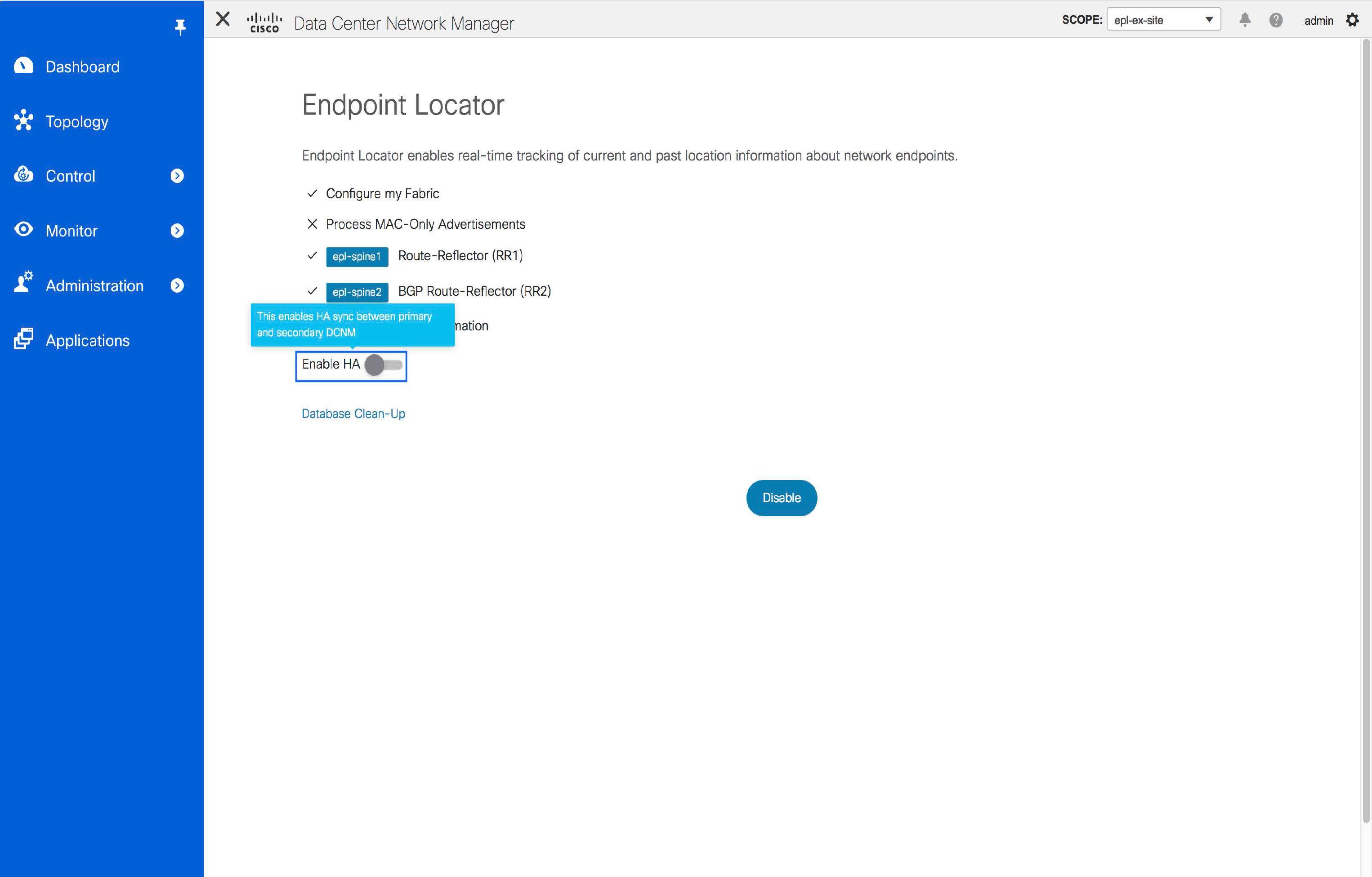
To enable high availability sync from the Cisco DCNM Web UI, perform the following steps:
Procedure
| Step 1 |
Choose Control > Endpoint Locator > Configure. |
| Step 2 |
Toggle the Enable HA button. |
Flushing the Endpoint Database
After you enable the Endpoint Locator feature, you can clean up or flush all the Endpoint information. This allows starting from a clean-slate with respect to ensuring no stale information about any endpoint is present in the database. After the database is clean, the BGP client re-populates all the endpoint information learnt from the BGP RR.
To flush all the Endpoint Locator information from the Cisco DCNM Web UI, perform the following steps:
Procedure
| Step 1 |
Choose Control > Endpoint Locator > Configure, and click Database Clean-Up.  A warning is displayed with a message indicating that all the endpoint information that is stored in the database will be flushed. |
| Step 2 |
Click Delete to continue or Cancel to abort. |
Configuring Endpoint Locator in DCNM High Availability Mode
Note |
For configuring EPL in native HA mode, you must add 2 neighbors to EPL. EPL IP being DCNM Primary eth2 and DCNM Secondary eth2 address respectively. |
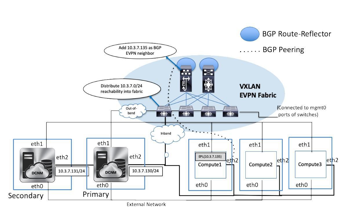
For production deployments, a native HA pair of DCNM nodes is recommended. Since the DCNM active and standby nodes need to be Layer-2 adjacent, their respective eth2 interfaces should be part of the same IP subnet or vlan. In addition, both DCNM nodes should be configured with the same eth2 gateway. The recommended option is to connect the DCNM active and standby nodes to a vPC pair of nexus switches (they may be leafs) so that there is enough fault-tolerance in case of single link failure, single device or a single DCNM node failure.
The following example shows a sample output for the appmgr update network-properties command for a Cisco DCNM Native HA Appliance. In this example, 1.1.1.2 is the primary eth2 interface IP address, 1.1.1.3 is the standby eth2 interface IP address, 1.1.1.1 is the default gateway and 1.1.1.4 is the virtual IP (VIP) for inband.
On Cisco DCNM Primary appliance:
appmgr update network-properties session start
appmgr update network-properties set ipv4 eth2 1.1.1.2 255.255.255.0 1.1.1.1
appmgr update network-properties set ipv4 peer2 1.1.1.3
appmgr update network-properties set ipv4 vip2 1.1.1.4 255.255.255.0
appmgr update network-properties session apply
appmgr update ssh-peer-trust
On Cisco DCNM Secondary appliance:
appmgr update network-properties session start
appmgr update network-properties set ipv4 eth2 1.1.1.3 255.255.255.0 1.1.1.1
appmgr update network-properties set ipv4 peer2 1.1.1.2
appmgr update network-properties set ipv4 vip2 1.1.1.4 255.255.255.0
appmgr update network-properties session apply
appmgr update ssh-peer-trust
After the in-band connectivity is established from both the Primary and Secondary nodes to the Fabric, to configure endpoint locator in DCNM HA mode from the Cisco DCNM Web UI, perform the following steps:
Procedure
| Step 1 |
Choose Control > Endpoint Locator > Configure. The Endpoint Locator window appears and the fabric configuration details are displayed. |
| Step 2 |
Select a fabric from the SCOPE dropdown list to configure endpoint locator in DCNM HA mode. |
| Step 3 |
Select the Route-Reflectors (RRs) from the drop-down lists. |
| Step 4 |
Select Yes under Collect Additional Information to enable collection of additional information such as PORT, VLAN, VRF etc. while enabling the EPL feature. If the No option is selected, this information will not be collected and reported by EPL. |
| Step 5 |
Click Submit. |
What to do next
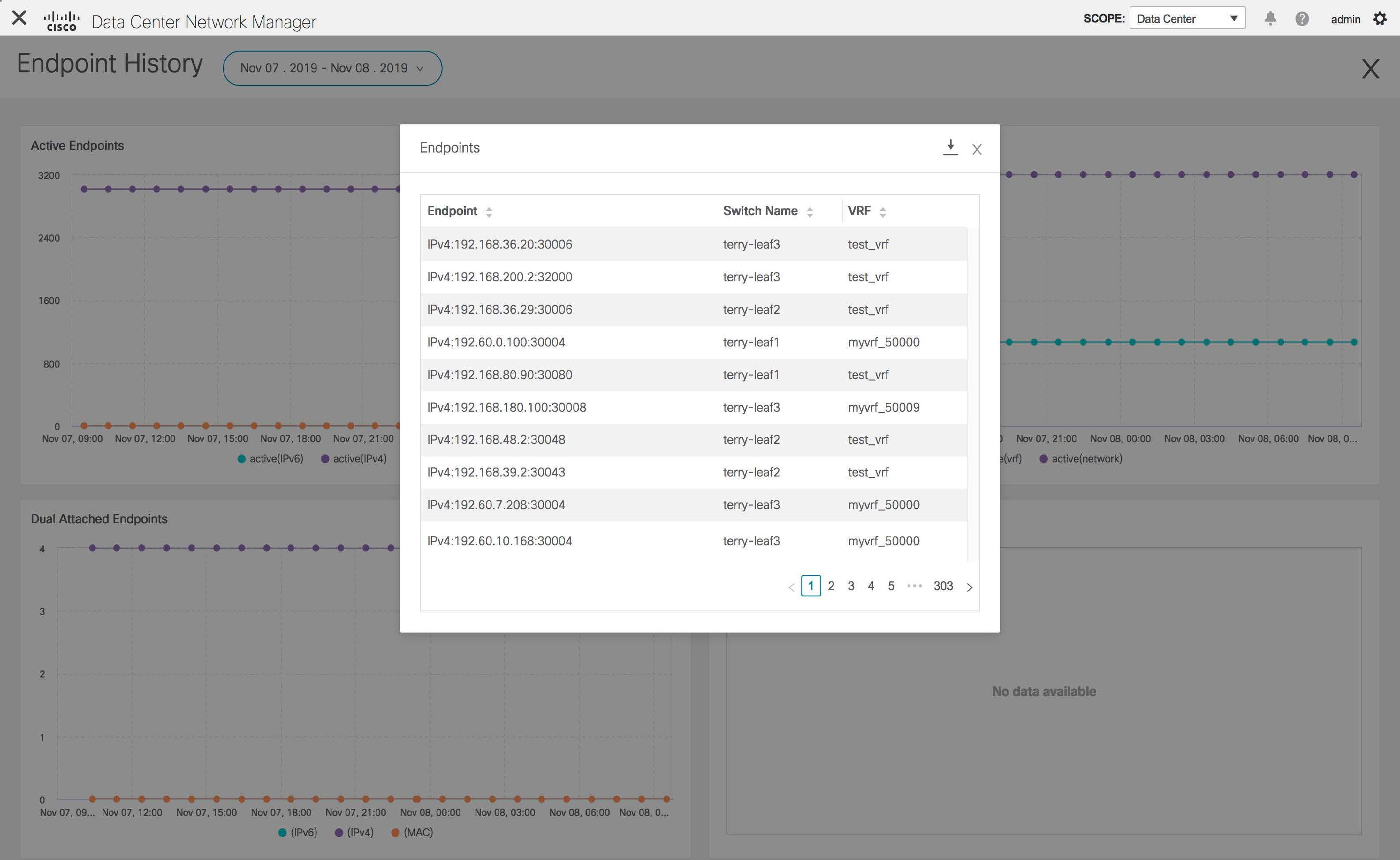
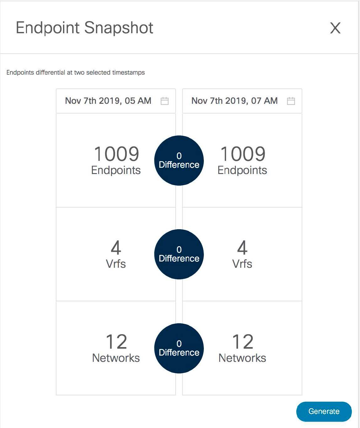
After you configure the Endpoint Locator in HA mode, you can view details such as Endpoint Activity and Endpoint History in the Endpoint Locator dashboard. To view these details, navigate to Monitor > Endpoint Locator > Explore.
Configuring Endpoint Locator in DCNM Cluster Mode
Note |
For configuring EPL in cluster mode, you must add a single neighbor to EPL. DCNM EPL container Inband IP address is EPL IP. |
With the DCNM cluster mode deployment, in addition to the DCNM nodes, an additional 3 compute nodes are present in the deployment. For information about deploying applications in cluster mode, see Cisco DCNM in Clustered Mode.
In DCNM Cluster mode, all applications including EPL run on the compute nodes. The DCNM application framework takes care of the complete life cycle management of all applications that run on the compute nodes. The EPL instance runs as a container that has its own IP address allocated out of the inband pool assigned to the compute nodes. This IP address will be in the same IP subnet as the one allocated to the eth2 or inband interface. Using this IP address, the EPL instance forms a BGP peering with the spines/RRs when the EPL feature is enabled. If a compute node hosting the EPL instance will go down, the EPL instance will be automatically respawned on one of the remaining 2 compute nodes. All IP addresses and other properties associated with the EPL instance are retained.
The Layer-2 adjacency requirement of the compute nodes dictates that the compute node eth2 interfaces should be part of the same IP subnet as the DCNM nodes. Again, in this case, connecting the compute nodes to the same vPC pair of switches is the recommended deployment option. Note that for cluster mode DCNM OVA setups, ensure that promiscuous mode is enabled in the port group corresponding to eth2 interface in order to establish inband connectivity as depicted below:

The enablement of the EPL feature for DCNM cluster mode is identical to that in the non-cluster mode. The main difference is that on the spine/RRs, only a single BGP neighborship is required that points to the IP address allocated to the EPL instance. Recall that for the DCNM native HA deployment in the non-cluster mode, all spines/RRs always had 2 configured BGP neighbors, one pointing to the DCNM primary eth2 interface and other one pointing to the DCNM secondary eth2 interface. However, only one neighbor would be active at any given time.
Configuring Endpoint Locator for External Fabrics
In addition to Easy fabrics, DCNM Release 11.2(1) allows you to enable EPL for VXLAN EVPN fabrics comprising of switches that are imported into the external fabric. The external fabric can be in managed mode or monitored mode, based on the selection of Fabric Monitor Mode flag in the External Fabric Settings. For external fabrics that are only monitored and not configured by DCNM, this flag is disabled. Therefore, you must configure BGP sessions on the Spine(s) via OOB or using the CLI. To check the sample template, click ℹ icon to view the configurations required while enabling EPL.
In case the Fabric Monitor Mode checkbox in the External Fabric settings is unchecked, then EPL can still configure the spines/RRs with the default Configure my fabric option. However, disabling EPL would wipe out the router bgp config block on the spines/RRs. To prevent this, the BGP policies must be manually created and pushed onto the selected spines/RRs.
Configuring Endpoint Locator for eBGP EVPN Fabrics
From Cisco DCNM Release 11.2(1), you can enable EPL for VXLAN EVPN fabrics, where eBGP is employed as the underlay routing protocol. Note that with an eBGP EVPN fabric deployment, there is no traditional RR similar to iBGP. The reachability of the in-band subnet must be advertised to the spines that behave as Route Servers. To configure EPL for eBGP EVPN fabrics from the Cisco DCNM Web UI, perform the following steps:
Procedure
| Step 1 |
Choose Control > Fabric Builder. Select the fabric to configure eBGP on or create eBGP fabric with the Easy_Fabric_eBGP template.  |
| Step 2 |
Use the leaf_bgp_asn policy to configure unique ASNs on all leaves.  |
| Step 3 |
Add the ebgp_overlay_leaf_all_neighbor policy to each leaf. Fill Spine IP List with the spines’ BGP interface IP addresses, typically the loopback0 IP addresses. Fill BGP Update-Source Interface with the leaf’s BGP interface, typically loopback0. 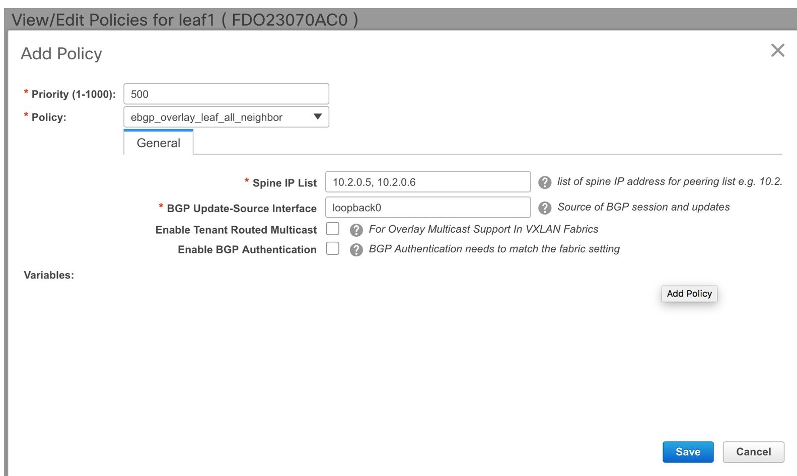 |
| Step 4 |
Add the ebgp_overlay_spine_all_neighbor policy to each spine. Fill Leaf IP List with the leaves’ BGP interface IPs, typically the loopback0 IPs. Fill Leaf BGP ASN with the leaves’ ASNs in the same order as in Leaf IP List. Fill BGP Update-Source Interface with the spine’s BGP interface, typically loopback0.  After the in-band connectivity is established, the enablement of the EPL feature remains identical to what is listed so far. EPL becomes a iBGP neighbor to the Route Servers running on the spines. |
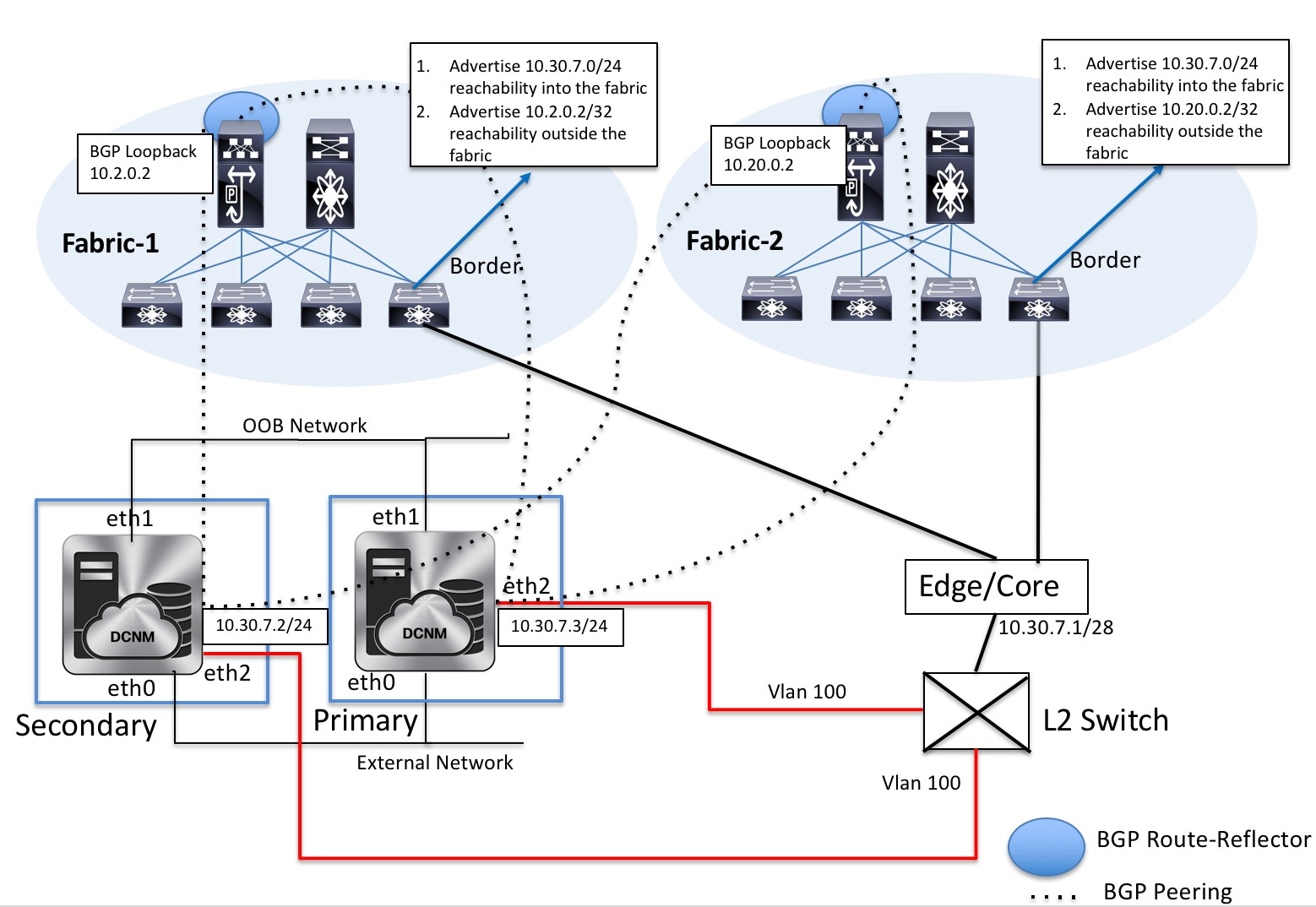
EPL Connectivity Options
Sample topologies for the varios EPL connectivity options are as given below.
Cisco DCNM supports the following web browsers:
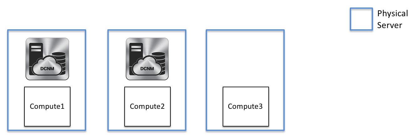
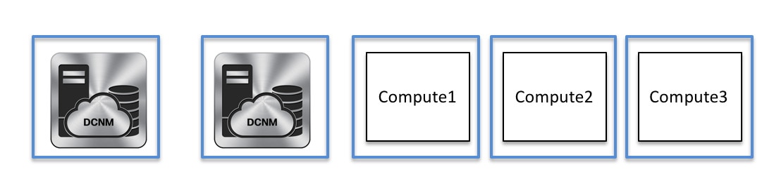
DCNM Cluster Mode: Physical Server to VM Mapping
We recommend a minimum of 3 physical servers, or a maximum of 5 physical servers in which each DCNM and compute is located on an individual physical server.
DCNM/Compute VM Physical Connectivity
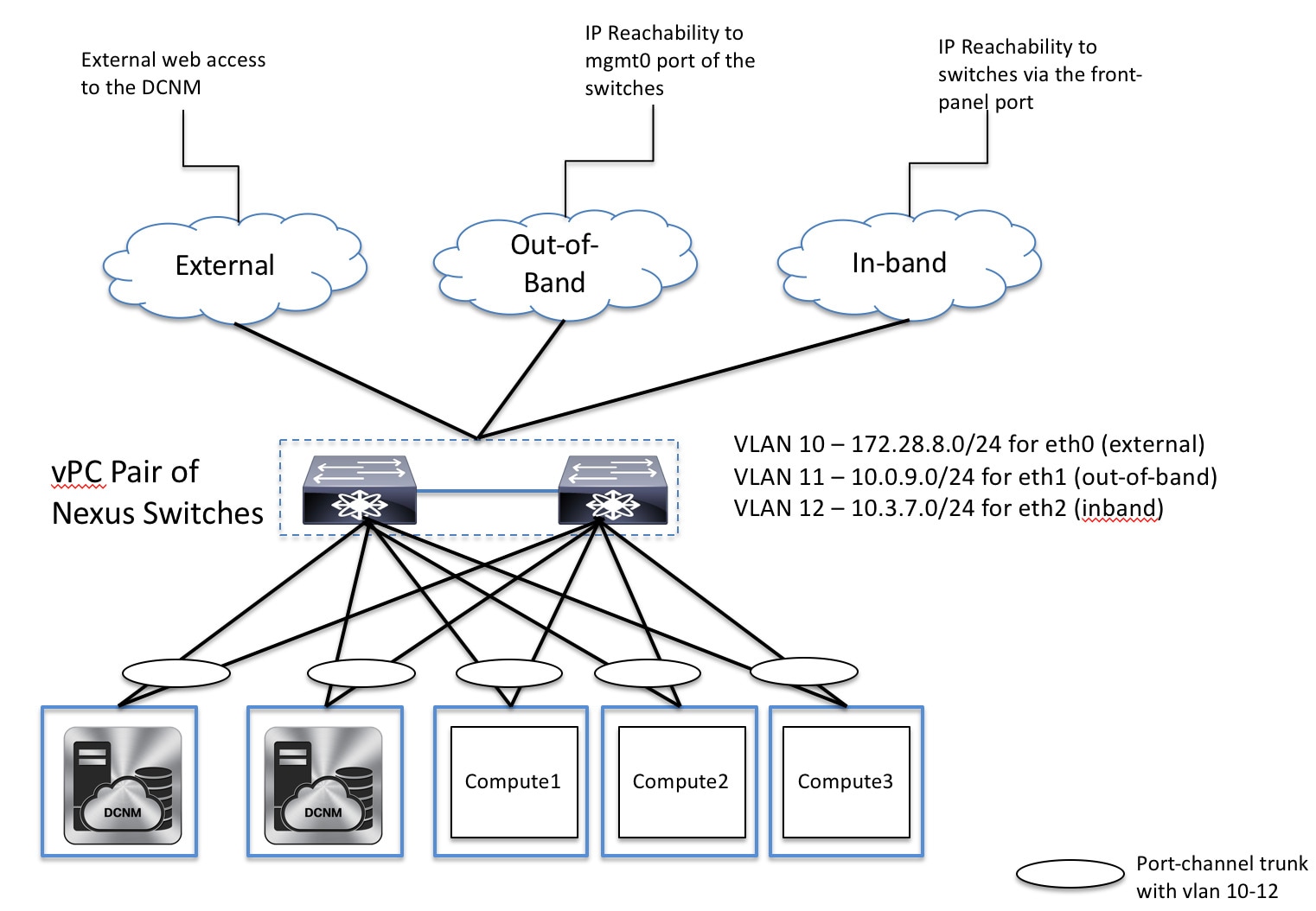
DCNM Cluster Mode
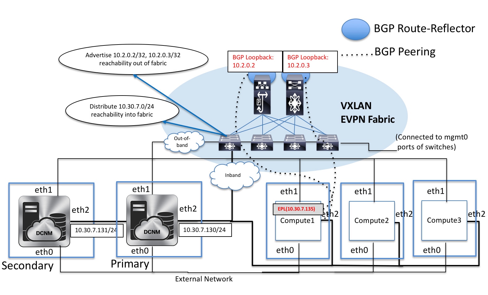
DCNM Multi-Fabric Connectivity
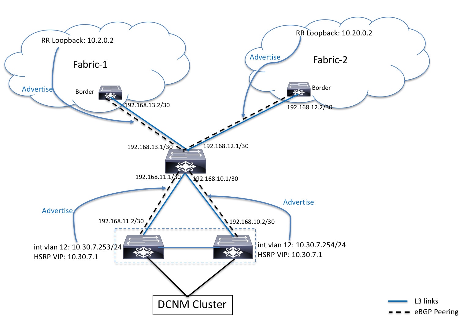
EPL Connectivity for Native HA
Disabling Endpoint Locator
Procedure
| Step 1 |
Choose Control > Endpoint Locator > Configure. The Endpoint Locator window appears. Select the required fabric from the SCOPE dropdown list. The fabric configuration details are then displayed for the selected fabric. |
| Step 2 |
Click Disable. |
Troubleshooting Endpoint Locator
There may be multiple reasons why enabling the Endpoint Locator feature may fail. Typically, if the appropriate devices are selected and the IP addresses to be used are correctly specified, the connectivity of the DCNM to the BGP RR may not be present due to which the feature cannot be enabled. This is a sanity check that is present to ensure that basic IP connectivity is available. The following image shows an example error scenario that was encountered during an attempt to enable the EPL feature.
The log that provides details on what occurred when the EPL feature is enabled or disabled, is present in the file epl.log at the location: /usr/local/cisco/dcm/fm/logs/epl.log. The following example provides a snapshot of the epl.log that shows the EPL configuration progress for a fabric.
2019.12.05 12:18:23  INFO  [epl] Found DCNM Active Inband IP: 192.168.94.55/24
2019.12.05 12:18:23  INFO  [epl] Running script: [sudo, /sbin/appmgr, setup, inband-route, --host, 11.2.0.4]
2019.12.05 12:18:23  INFO  [epl] Getting EPL configure progress for fabric 4
2019.12.05 12:18:23  INFO  [epl] EPL Progress 2
2019.12.05 12:18:23  INFO  [epl] [sudo, /sbin/appmgr, setup, inband-route, --host, 11.2.0.4] command executed, any errors? No
2019.12.05 12:18:23  INFO  [epl] Received response:
2019.12.05 12:18:23  INFO  [epl] Validating host route input
2019.12.05 12:18:23  INFO  [epl] Done configuring host route
2019.12.05 12:18:23  INFO  [epl] Done.
2019.12.05 12:18:23  INFO  [epl] Running script: [sudo, /sbin/appmgr, setup, inband-route, --host, 11.2.0.5]
2019.12.05 12:18:23  INFO  [epl] [sudo, /sbin/appmgr, setup, inband-route, --host, 11.2.0.5] command executed, any errors? No
2019.12.05 12:18:23  INFO  [epl] Received response:
2019.12.05 12:18:23  INFO  [epl] Validating host route input
2019.12.05 12:18:23  INFO  [epl] Done configuring host route
2019.12.05 12:18:23  INFO  [epl] Done.
2019.12.05 12:18:23  INFO  [epl] Running command: sudo /sbin/appmgr show inband
2019.12.05 12:18:24  INFO  [epl] Received response: Physical IP=192.168.94.55/24
Inband GW=192.168.94.1
No IPv6 Inband GW found

2019.12.05 12:18:26  INFO  [epl] Call: http://localhost:35000/afw/apps?imagetag=cisco:epl:2.0&fabricid=epl-ex-site, Received response: {"ResponseType":0,"Response":[{"Name":"epl_cisco_epl-ex-site_afw","Version":"2.0","FabricId":"epl-ex-site","ImageTag":"cisco:epl:2.0","TotalReplicaCount":1,"Url":"","Category":"Application","Status":"NoReplicas","RefCount":0,"Deps":["elasticsearch_Cisco_afw","kibana_cisco_afw"],"RunningReplicaCount":0,"ApplicationIP":"172.17.8.23","Members":{},"MemberHealth":{},"ReplicationMode":1,"services":null,"Upgradable":false}]}
2019.12.05 12:18:26  INFO  [epl] Epl started on AFW
After the EPL is enabled successfully, all the debug, error, and info logs associated with endpoint information are stored in /var/afw/applogs/ under the directory for the associated fabric. For example, if EPL is enabled for the test fabric, the logs will be in /var/afw/applogs/epl_cisco_test_afw_log/epl/ starting with filename afw_bgp.log.1. Depending on the scale of the network and the number of endpoint events, the file size will increase. Therefore, there is a restriction on the maximum number and size of afw_bgp.log. Up to 10 such files will be stored with each file size of maximum of 100 MB.
Note |
EPL creates a symlink in this directory inside the docker container, hence it appears broken when accessed natively. |
The EPL relies on BGP updates to get endpoint information. In order for this to work, the switch loopback or VTEP interface IP addresses must be discovered on the DCNM for all switches that have endpoints. To validate, navigate to the Cisco DCNM Web UI > Dashboard > Switch > Interfaces tab, and verify if the IP address and the prefix associated with the corresponding Layer-3 interfaces (typically loopbacks) are displayed correctly.
In a Cisco DCNM Cluster deployment, if EPL cannot establish BGP peering and the active DCNM is able to ping the loopback IP address of the spine, while the EPL container cannot, it implies that the eth2 port group for Cisco DCNM and its computes does not have Promiscuous mode set to Accept. After changing this setting, the container can ping the spine and EPL will establish BGP.
In a large-scale setup, it may take more than 30 seconds (default timer set in Cisco DCNM) to get this information from the switch. If this occurs, the ssh.read-wait-timeout property (in the Administration > DCNM Server > Server Properties) must be changed from 30000 (default) to 60000 or a higher value.
The endpoint data displayed on the dashboard may be slightly inaccurate in a large-scale setup. An approximately 1% accuracy tradeoff is made at higher endpoint counts for performance. If the dashboard greatly differs from what is expected, the validity can be checked with a verifier script that is packaged in DCNM. As root, run the epl-rt-2.py script in /root/packaged-files/scripts/. This script needs the RR/spine IP and the associated username and password. Note that the /root/packaged-files/scripts/ directory is read only, so the script needs to be run outside that directory. For example, to run the script for a spine with IP 10.2.0.5, username admin, and password cisco123, run /root/packaged-files/scripts/epl-rt-2.py -s 10.2.0.5 -u admin -p cisco123 while the working directory is /root/. If the EPL dashboard still does not display expected numbers and the epl-rt-2.py script output differs significantly from the dashboard, please contact tech support.
In cluster mode, BGP is not established between the spines/RRs and DCNM. Check that the Promiscuous mode setting for the port group corresponding to the eth2 DCNM interface is set to Accept. If a connection is still not established, perform the following steps to check the connectivity between DCNM's BGP client and the spine/RR:
-
Open a shell on the active DCNM and run the following commands:
-
docker service ls
*Note the ID for the EPL service
-
docker service ps $ID
*Note the NODE field
-
afw compute list -b
*Note the HostIp matching the HostName (NODE) from before. This is the compute that the EPL service is currently running on.
-
-
Open a shell on the compute noted from Step 1 - c and run the following commands:
-
docker container ls
*Note the CONTAINER ID for EPL. If there are multiple EPL containers check the container name to see which one corresponds to which fabric. The naming scheme is epl_cisco_$FabricName_afw.*
-
docker container inspect $CONTAINER_ID
*Note the value of SandboxKey
-
nsenter --net=$SandboxKey
This command enters the network namespace of the EPL container. Now network commands such as ifconfig, ip, and ping will act as if they're being ran from inside the container until "exit" is issued in the shell.
-
-
Try pinging the spine/RR. Make sure that the Inband IP Pool that the DCNM cluster is configured with does not conflict with any switch loopback IPs.


 Feedback