Configuring MPLS Layer 2 VPN over GRE

Information About MPLS Layer 2 VPN over GRE

The MPLS Layer 2 VPN over GRE feature provides a mechanism for tunneling Multiprotocol Label Switching (MPLS) packets over non-MPLS networks. This feature allows you to create a generic routing encapsulation (GRE) tunnel across a non-MPLS network. The MPLS packets are encapsulated within the GRE tunnel packets, and the encapsulated packets traverse the non-MPLS network through the GRE tunnel. When GRE tunnel packets are received at the other side of the non-MPLS network, the GRE tunnel packet header is removed and the inner MPLS packet is forwarded to its final destination.

To configure MPLS Layer 2 VPN over GRE, you must have configured either Virtual Private LAN Service (VPLS) or EoMPLS (Ethernet over MPLS).

Types of Tunneling Configurations

The following sections provide information about the different types of tunneling configurations that are supported.
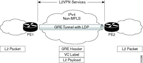
PE-to-PE Tunneling

The provider edge-to-provider edge (PE-to-PE) tunneling configuration provides a scalable way to connect multiple customer networks across a non-MPLS network. With this configuration, traffic that is destined to multiple customer networks is multiplexed through a single GRE tunnel.

The PE device on one side of the non-MPLS network uses the routing protocols (that operate within the non-MPLS network) to learn about the PE device on the other side of the non-MPLS network. The learned routes that are established between the PE devices are then stored in the main or default routing table.

The opposing PE device uses Border Gateway Protocol (BGP) to learn about the routes that are associated with the customer networks that are behind the PE devices. These learned routes are not known to the non-MPLS network.

PE-to-PE Tunneling shows an end-to-end IP core from one PE device to another through the GRE tunnel that spans the non-MPLS network.

Figure 1. PE-to-PE Tunneling

P-to-PE Tunneling

P-to-PE Tunneling shows a method of connecting two MPLS segments (P2 to PE2) across a non-MPLS network. In this configuration, MPLS traffic that is destined to the other side of the non-MPLS network is sent through a single GRE tunnel.

Figure 2. P-to-PE Tunneling

P-to-P Tunneling

P-to-P Tunneling shows a method of connecting two MPLS segments (P1 to P2) across a non-MPLS network. In this configuration, MPLS traffic that is destined to the other side of the non-MPLS network is sent through a single GRE tunnel.

Figure 3. P-to-P Tunneling

How to Configure MPLS Layer 3 VPN over GRE

To configure the MPLS over GRE feature, you must create a GRE tunnel to span the non-MPLS networks. Perform the following procedure on the devices that are located at both ends of the GRE tunnel.

Procedure

  Command or Action Purpose

Step 1

enable

Example:

Device> enable

Enables privileged EXEC mode.

Enter your password, if prompted.

Step 2

configure terminal

Example:

Device# configure terminal

Enters global configuration mode.

Step 3

interface tunnel tunnel-number

Example:

Device(config)# interface tunnel 1

Creates a tunnel interface and enters interface configuration mode.

Step 4

ip address ip-address mask

Example:

Device(config-if)# ip address 10.0.0.1 255.255.255.0

Assigns an IP address to the tunnel interface.

Step 5

tunnel source source-address

Example:

Device(config-if)# tunnel source 10.1.1.1

Configures the tunnel’s source IP address.

Step 6

tunnel destination destination-address

Example:

Device(config-if)# tunnel destination 10.1.1.2

Configures the tunnel’s destination IP address.

Step 7

mpls ip

Example:

Device(config-if)# mpls ip

Enables MPLS on the tunnel’s physical interface.

Step 8

end

Example:

Device(config-if)# end

Returns to privileged EXEC mode.

Configuration Examples for MPLS Layer 2 VPN over GRE

The following section provides an example for configuring MPLS Layer 2 VPN over GRE.

Example: Configuring a GRE Tunnel That Spans a non-MPLS Network

The following examples show how to configure a generic GRE tunnel configuration that spans a non-MPLS network.

The following example shows the tunnel configuration on the PE1 device:

Device> enable
Device# configure terminal
Device(config)# interface Tunnel 1
Device(config-if)# ip address 10.1.1.1 255.255.255.0
Device(config-if)# tunnel source 10.0.0.1
Device(config-if)# tunnel destination 10.0.0.2
Device(config-if)# ip ospf 1 area 0
Device(config-if)# mpls ip

The following example shows the tunnel configuration on the PE2 device:

Device> enable
Device# configure terminal
Device(config)# interface Tunnel 1
Device(config-if)# ip address 10.1.1.2 255.255.255.0
Device(config-if)# tunnel source 10.0.0.2
Device(config-if)# tunnel destination 10.0.0.1
Device(config-if)# ip ospf 1 area 0
Device(config-if)# mpls ip

Additional References for Configuring MPLS Layer 2 VPN over GRE

Related Documents

Related Topic Document Title

Configuring VPLS

For more information, see Information About VPLS.

Configuring Ethernet-over-MPLS (EoMPLS) and Pseudowire Redundancy (PWR)

For more information, see How to Configure Ethernet Over MPLS.

Feature History for Configuring MPLS Layer 2 VPN over GRE

This table provides release and related information for the features explained in this module.

These features are available in all the releases subsequent to the one they were introduced in, unless noted otherwise.

Release

Feature

Feature Information

Cisco IOS XE Gibraltar 16.12.1

MPLS Layer 2 VPN over GRE

The MPLS Layer 2 VPN over GRE feature provides a mechanism for tunneling MPLS packets over non-MPLS networks.

Use the Cisco Feature Navigator to find information about platform and software image support. To access Cisco Feature Navigator, go to https://cfnng.cisco.com/

http://www.cisco.com/go/cfn.