MPLS VPN Inter-AS IPv4 BGP Label Distribution
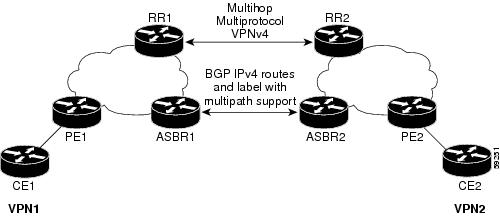
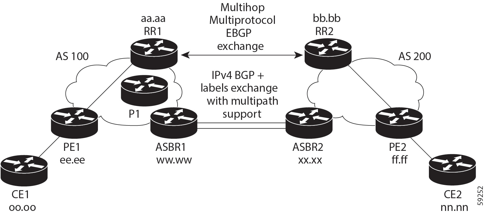
This feature enables you to set up a Virtual Private Network (VPN) service provider network. In this network, the Autonomous System Boundary Routers (ASBRs) exchange IPv4 routes with Multiprotocol Label Switching (MPLS) labels of the provider edge (PE) routers. Route reflectors (RRs) exchange VPNv4 routes by using multihop, multiprotocol, External Border Gateway Protocol (EBGP). This configuration saves the ASBRs from having to store all the VPNv4 routes. Using the route reflectors to store the VPNv4 routes and forward them to the PE routers results in improved scalability.
The MPLS VPN—Inter-AS—IPv4 BGP Label Distribution feature has the following benefits:
-
Having the route reflectors store VPNv4 routes results in improved scalability—This configuration scales better than configurations where the ASBR holds all the VPNv4 routes and forwards the routes based on VPNv4 labels. With this configuration, route reflectors hold the VPNv4 route, which simplifies the configuration at the border of the network.
-
Enables a non-VPN core network to act as a transit network for VPN traffic—You can transport IPv4 routes with MPLS labels over a non MPLS VPN service provider.
-
Eliminates the need for any other label distribution protocol between adjacent LSRs—If two adjacent label switch routers (LSRs) are also BGP peers, BGP can handle the distribution of the MPLS labels. No other label distribution protocol is needed between the two LSRs.
-
Includes EBGP multipath support to enable load balancing for IPv4 routes across autonomous system (AS) boundaries.


 Feedback