Servicing the Fabric Interconnect

This chapter contains the following topics:

Installing and Removing the Top Cover

The top cover for the Cisco UCS X-Series Direct 9108 100G Fabric Interconnect can be removed to allow access to internal components, some of which are field-replaceable. The top cover has a release button on one side and an emboss on the other side.

  • the release button unlocks the cover so that it can be removed from the fabric interconnect

  • the emboss provides a second fingerhold so that you can apply equal force to both sides of the cover.
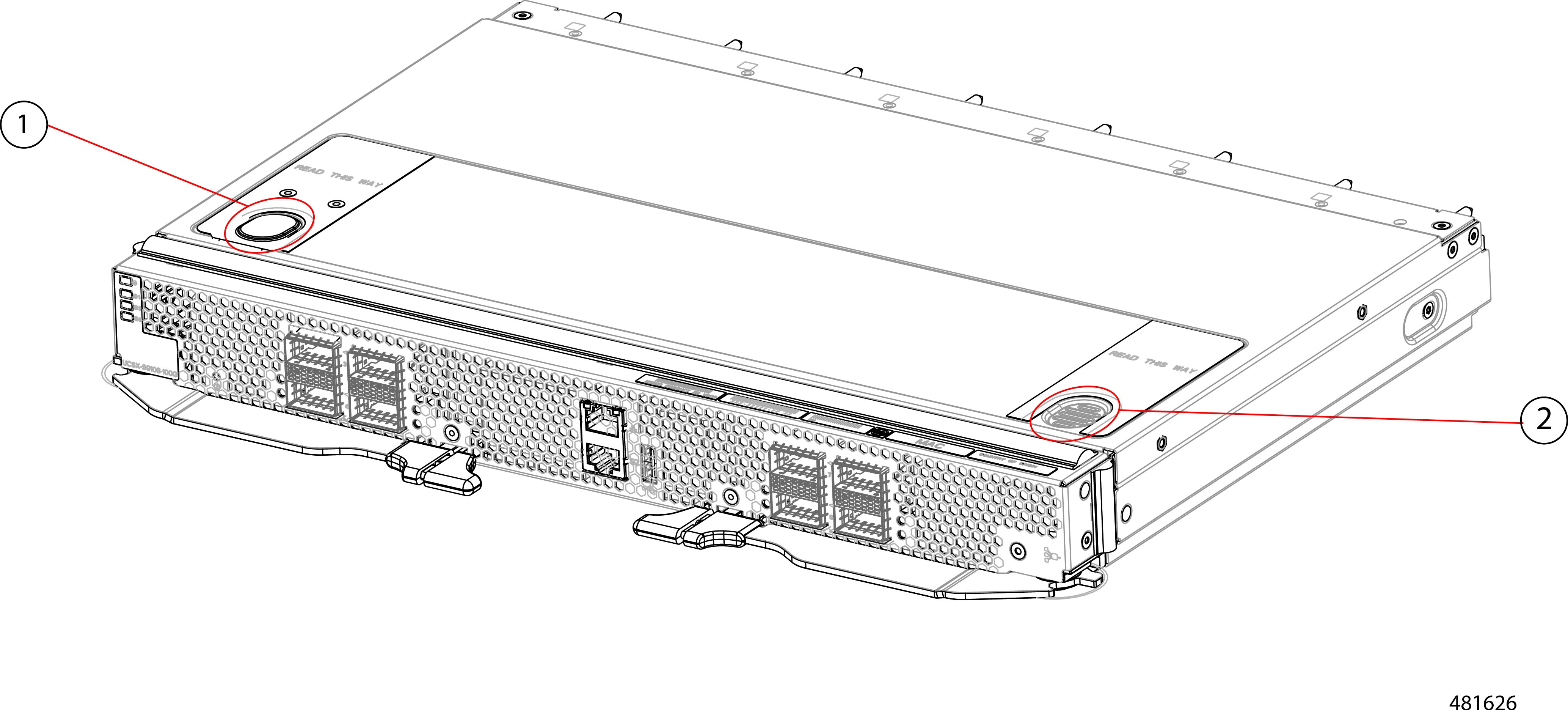
1

Release Button

2

Emboss, which can be used as a fingerhold

To remove and install the top cover, use the following procedures:

Installing the Top Cover

The top cover must be installed on the fabric interconnect during normal runtime operation. Make sure to keep the top cover in place whenever you are not actively working on the fabric interconnect.

Use the following task to install the top cover.

Before you begin

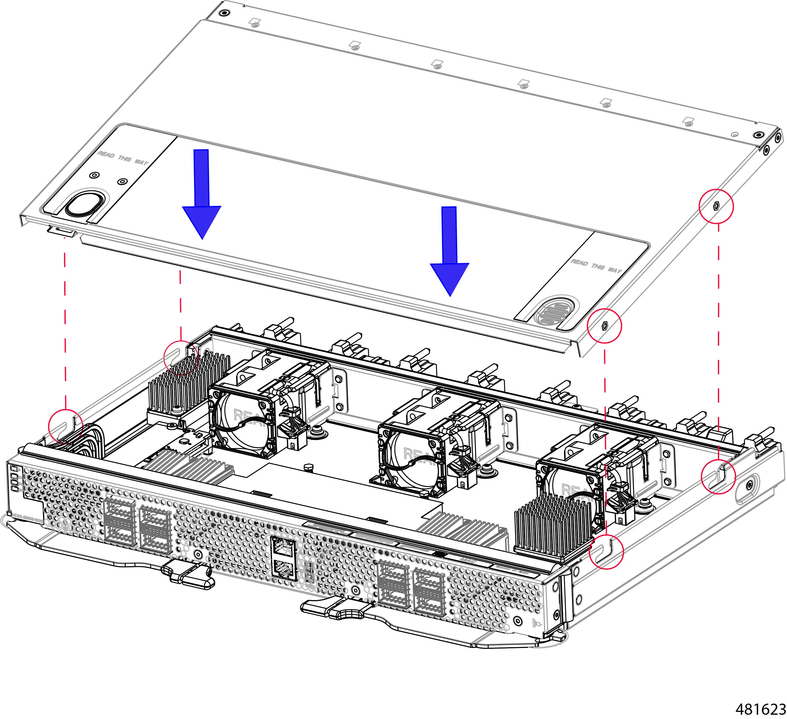
The top cover has alignment features consisting of catch pins on the inside of the top cover and cutouts in the fabric interconnect's sidewalls. The module can be installed successfully when these features meet.

Procedure


Step 1

Align the top cover over the fabric interconnect.

Step 2

Lower the top cover onto the fabric interconnect while slightly tilting the front edge of the cover down.

Step 3

Making sure that the top cover sits flush on the fabric interconnect, slide the top cover towards the front panel until the catch pins insert into their cutouts.

Note


You can use the button and emboss on the top cover to ensure you apply equal force to both sides of the top cover while sliding it into place.

The front edge of the top cover must slide under the edge of the front panel. When the top cover is completely installed, the release button clicks.


What to do next

When you are ready, re-install the fabric interconnect into the chassis. See Installing the Fabric Interconnect.

Removing the Top Cover

The fabric interconnect has a sheetmetal top cover that protects components and facilitates proper ventilation and cooling. Follow this procedure to remove the top cover.

Before you begin

To service the fabric interconnect components, you must remove the top cover. If you have not already removed the fabric interconnect from the server chassis, remove it now. See Removing the Fabric Interconnect.

Procedure


Step 1

Lay the fabric interconnect flat on an ESD-safe work surface.

Step 2

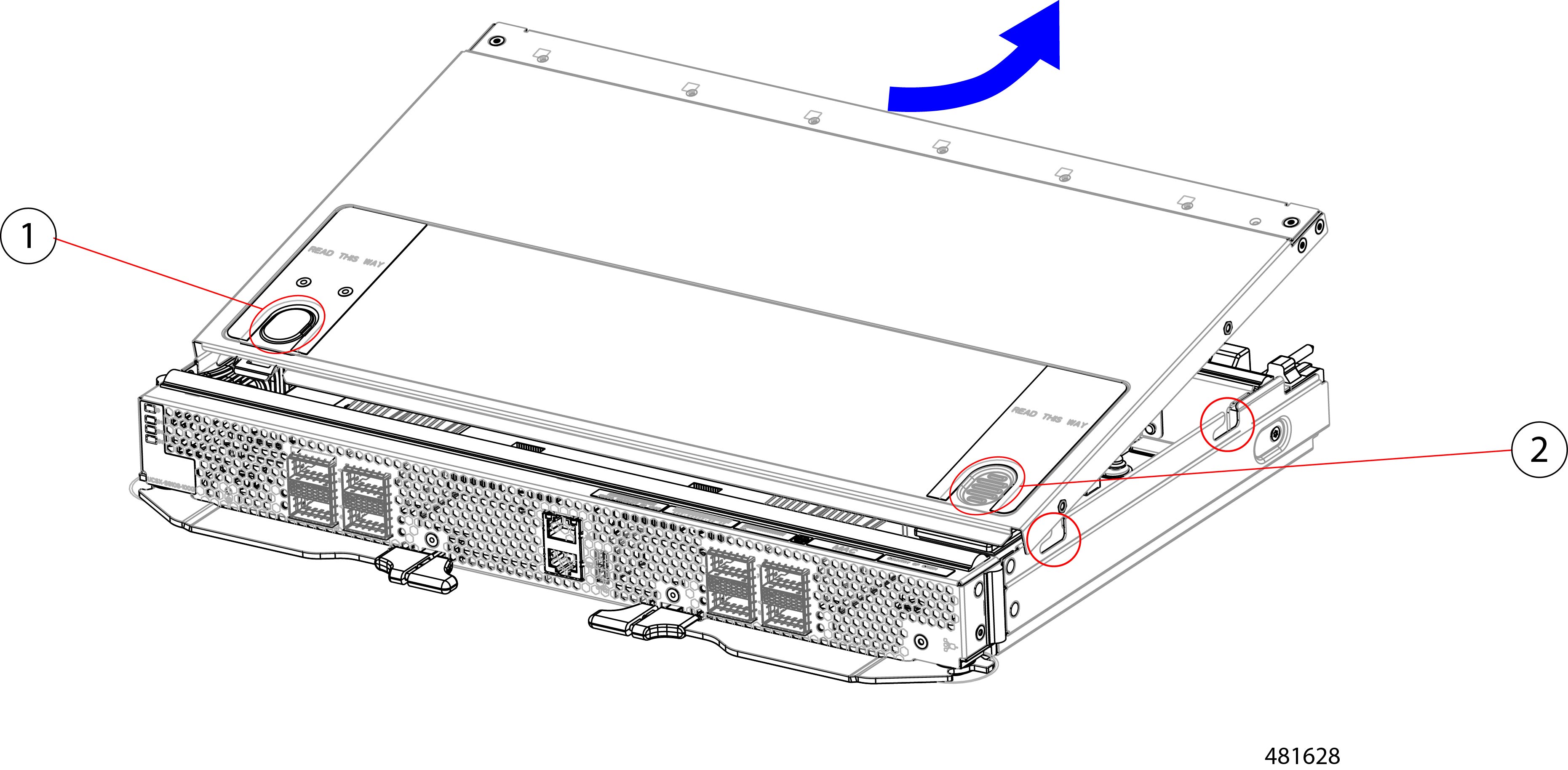
Using your fingers, press the release button until it clicks.

Step 3

Using the release button and the embossed fingerhold, slide the top cover back (away from the front panel), while slightly lifting up on the rear end of the top cover.

Gently lifting the rear end of the top cover should help release pressure on the opposite end and enable the top cover's front edge to slide out from under the fabric interconnect's sheetmetal edge.

Note


Make sure to slide the top cover far enough that the catch pins clear the cutouts in the sheetmetal.

1

Release Button

2

Embossed fingerhold


What to do next

After performing any maintenance work on the fabric interconnect, reinstall the top cover. See Installing the Top Cover.
Fabric Interconnect Components

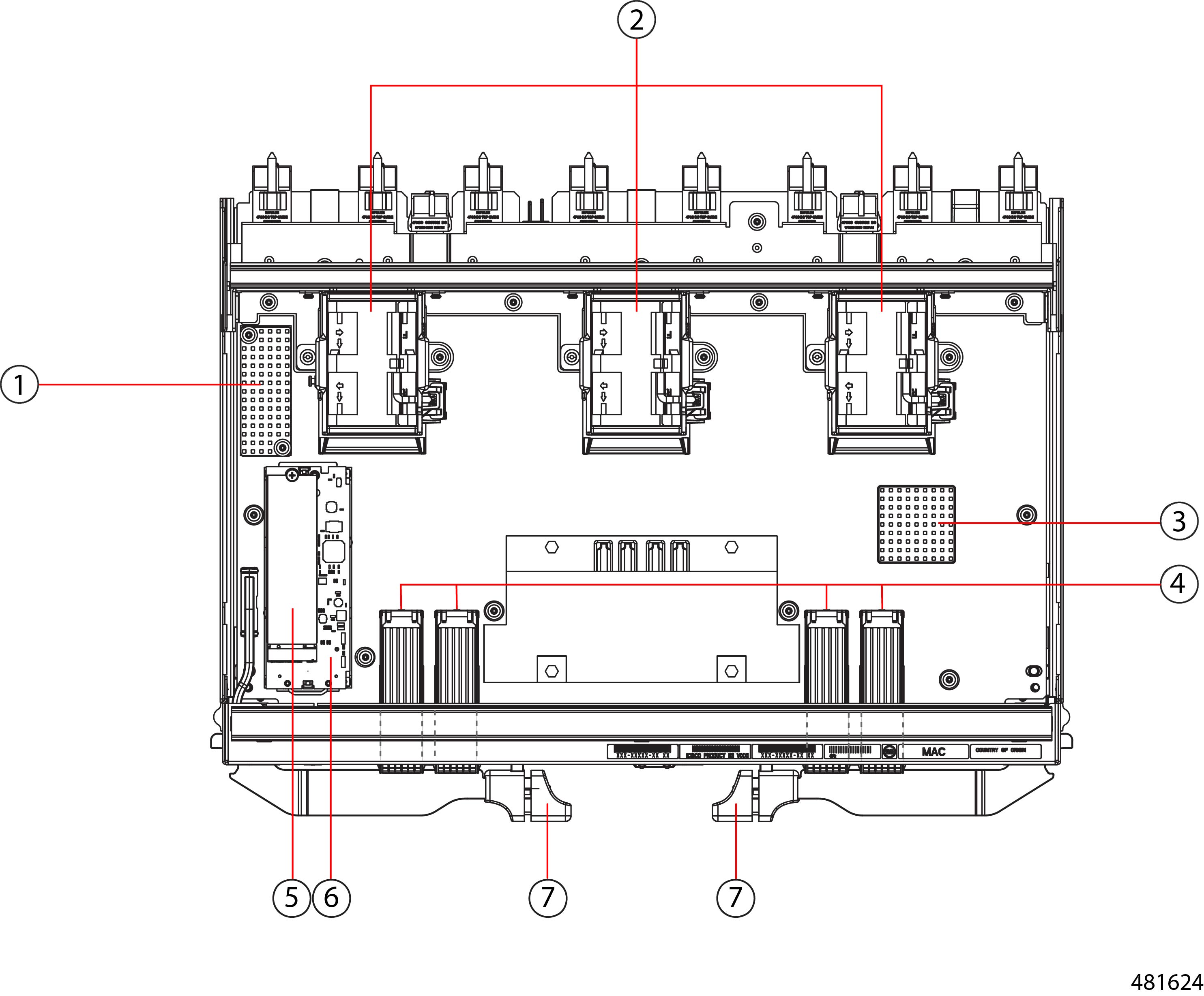
The Cisco UCS X-Series Direct Fabric Interconnect 9108 100G (UCSX-S9108-100G) has the following board-level components.
Figure 1. Fabric Interconnect, Component View

1

Heatsink, not field replaceable

2

Fans, (UCSX-RSFAN=), three, which are numbered 1 through 3 starting with the left fan

3

Heatsink, not field replaceable

4

QSFP28 Optical Ports.

Ports are arranged in two groups of four physical ports. Ports are stacked in vertical pairs, with two ports in each vertical port stack.

From left to right:

Port number 1 is the top port of the left port pair in this group, and port number 3 is the top port of the right port pair in the group.

Port number 5 is the top port in the left port pair of this group, and port number 7 is the top port in the right port pair of the group.

5

M.2 240G SATA, one.

6

Mini-storage carrier that holds the M.2 SATA SSD.

7

Ejector handles, two, one per side.

Ejector handles lock when the fabric interconnect is installed.

Cisco UCS X-Series Direct Fabric Interconnect Module Field Replaceable Unit Replacement Instructions

The rear of the Cisco UCS X9508 contains two module bays for the UCS X-Series Direct Fabric Interconnect 9108 100G (fabric interconnect modules) above the fans.

Refer to the following illustration for information about field-replacement options on the fabric interconnect module.

Figure 2. Cisco UCS X-Series Direct Fabric Interconnect 9108 100G Module (UCSX-S9108-100G) FRU Replacement Instructions

Installing and Removing the Fabric Interconnect Fans

The Cisco UCS X-Series Direct Fabric Interconnect 9108 100G contains on-board fans (UCSX-RSFAN=). These fans are interchangeable between the fabric interconnect and the UCS Intelligent Fabric Modules (IFMs), but not interchangeable with the fans in the Cisco UCS X9508 Server Chassis. In a typical configuration, there are three fans numbered from one to three on the fabric interconnect.


Note


The fans for the fabric interconnect (UCSX-RSFAN=) are different from the chassis fan modules (UCSX-9508-FAN) that provide cooling and ventilation for the entire server chassis. These two types of fans are not interchangeable.


Use the following procedures to replace a fan on a fabric interconnect.

Removing a Fabric Interconnect Fan

Use the following procedure to remove a fan from the fabric interconnect.

Procedure


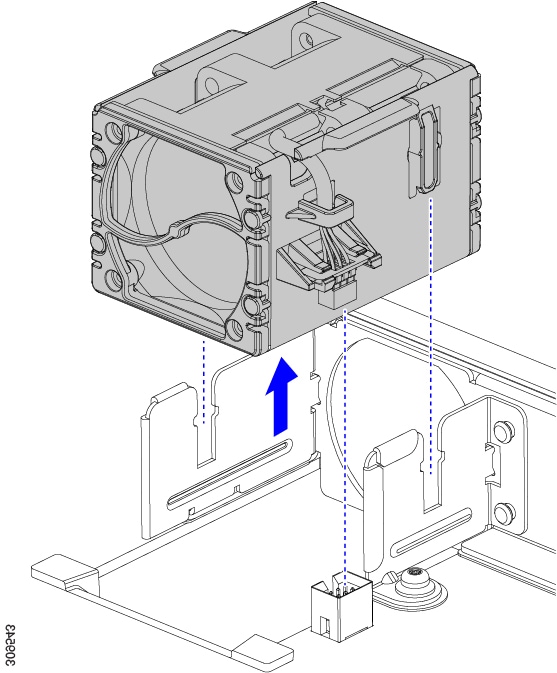
Step 1

Grasp the fan by the tabs on each long side wall.

Step 2

Pull the fan straight up.

This step disconnects the fan from the power connector and lifts the fan off of the board.

Figure 3. Removing the Fan from a Fabric Interconnect

What to do next

Insert a fan module. Go to Installing a Fabric Interconnect Fan.

Installing a Fabric Interconnect Fan

Use this task to install the fan (UCSX-RSFAN=) for a fabric interconnect.

Procedure


Step 1

Align the fan correctly.

  1. Align the power connector on the replacement fan with power connector on the board.

  2. Align the guides on long fan side walls with the corresponding cutouts on the module.

    Figure 4. Aligning the Fan

Step 2

Press down evenly on the fan until it is fully seated.

Make sure the fan is level while you're installing it. You will feel the fan click into place when it is correctly seated on the module or module blank.


Installing and Removing a Fabric Interconnect M.2 Mini Storage Module

Each fabric interconnect has its own onboard storage capability in the form of an M.2 mini storage module. Each mini storage module consists of a sled (or carrier) and a M.2 240G SATA SSD. The M.2 storage module can be interchanged between fabric interconnects in the chassis. The M.2 storage modules are field replaceable, as is the sled.

Use the following procedures to replace an M.2 mini-storage module:

Mini-Storage Considerations

When installing or removing the mini-storage module or its SSD, be aware of the following:

  • The M.2 SSDs must be SATA.

  • The socket for the SSD is on the top side of the carrier. Make sure that this SSD is facing up when installing the mini-storage module onto the fabric interconnect.

Removing a Fabric Interconnect M.2 Mini-Storage Module

Use this task to remove the fabric interconnect's M.2 mini-storage module.

Procedure


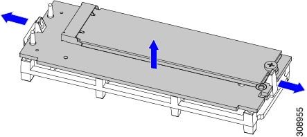
Step 1

Using your fingers, pull the retention clips outward to release pressure on the M.2 mini storage module, and disengage it from the carrier.

Step 2

Grasp the M.2 module by the long sides and pull up to remove it from the carrier.

Figure 5. Detaching and Removing the M.2 Mini Storage Module

What to do next

Insert a new M.2 storage module. Go to Installing a Fabric Interconnect M.2 Mini Storage Module.

Installing a Fabric Interconnect M.2 Mini Storage Module

Use this task to install an M.2 mini storage module into the fabric interconnect's M.2 module carrier.

Procedure


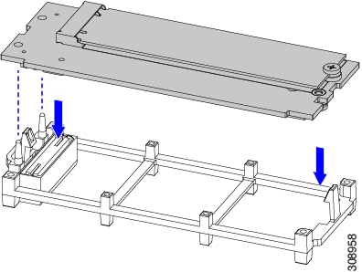
Step 1

Holding the module by the long sides, align the two holes on the module's short side with the retention pins on the M.2 module holder.

Figure 6. Aligning and Installing the M.2 Mini Storage Module

Step 2

Push on the four corners of the carrier to fully seat it.

Make sure the M.2 module is level while seating it into the carrier. The module is correctly seated when it clicks into place and both retention clips are engaged.


Installing and Removing a Mini-Storage SSD

The mini-storage module plugs into a motherboard socket to provide additional internal storage. The mini-storage module contains one M.2 form factor SSD.

To install or remove the mini-storage SSD, see:

Removing a Mini Storage SSD

This topic describes how to remove and replace an M.2 SATA SSD in a mini-storage module. The module has one M.2 SSD socket on its top.

Before you begin

To access the M.2 SSD, the mini-storage module must be removed from the fabric interconnect. If you have not already removed the mini-storage module, do so now. See Removing a Fabric Interconnect M.2 Mini-Storage Module.

Get a #1 Phillips screwdriver.

Procedure


Step 1

With the mini-storage module removed from the fabric interconnect, use a #1 Phillips-head screwdriver to remove the single screw that secures the M.2 SSD to the carrier.

Step 2

Lift the M.2 SSD from its socket on the carrier.

You might need to tilt and slide the SSD to clear the socket opposite the screw.


What to do next

Install an M.2 SSD. See Installing a Mini Storage SSD.

Installing a Mini Storage SSD

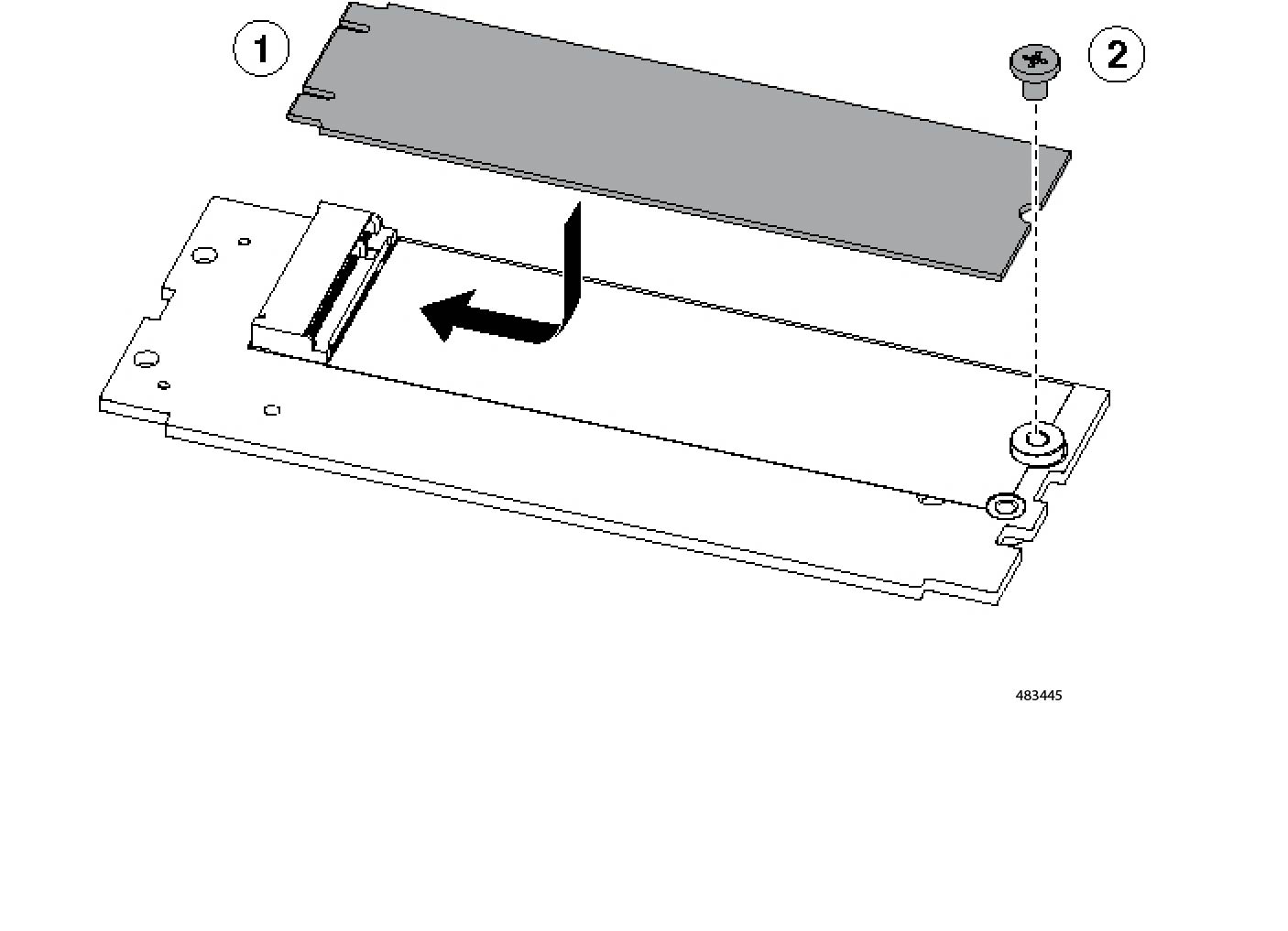
Use this task to install or reinstall the M.2 SSD onto the mini-storage module.

Before you begin

You will need a #1 Phillips screwdriver to complete this task.

Procedure


Step 1

Position the replacement M.2 drive over the socket on the mini-storage module.

Step 2

Angle the M.2 drive downward and insert the connector-end into the socket on the carrier. The M.2 drive's label must face up.

Step 3

Press the M.2 drive flat against the carrier.

Step 4

Install the single screw that secures the end of the M.2 SSD to the carrier.

Figure 7. Showing M.2 Drive Installation