Cisco Unified IP Phone Non-Lockable Wall Mount

ADA Non-Lockable Wall Mount Kit for 6900 Series

This section describes how to install the ADA Non-Lockable Wall Mount Kit for 6900 Series on a Cisco Unified IP Phone 6911, 6921, 6941, 6945, and 6961.

The nonlocking wall mount kit meets ADA 4.4.1 requirements.

Figure 1. Back View of ADA Non-Lockable Wall Mount Kit Installed on Phone. The following figure shows the wall mount kit installed on the phone.
Figure 2. Side View of ADA Non-Lockable Wall Mount Kit Installed on Phone. The following figure shows the phone with the wall mount kit from the side.

Components

Figure 3. Components. The following figure shows the contents of the Wall Mount kit.


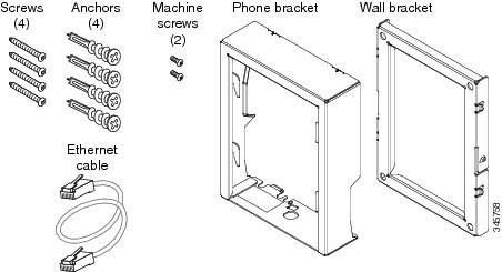
The package includes these items:

  • One phone bracket

  • One wall bracket

  • Four #8-18 x 1.25-inch Phillips-head screws with four anchors

  • Two M2.5 x 6 mm machine screws

  • One 6-inch Ethernet cable

Before You Begin

You need these tools to install the bracket:

  • #1 and #2 Phillips-head screwdrivers

  • Level

  • Pencil

You must also install an Ethernet jack for the telephone in the desired location if an Ethernet jack does not currently exist. This jack must be wired appropriately for an Ethernet connection. You cannot use a regular telephone jack.

Install Non-Lockable Wall Mount Kit for Phone

The wall mount kit can be mounted on most surfaces, including concrete, brick, and similar hard surfaces. To mount the kit on concrete, brick, or similar hard surfaces, you must provide the appropriate screws and anchors for your wall surface.

Procedure


Step 1

Mount the wall bracket in the desired location. You can install the bracket over an Ethernet jack, or you can run the Ethernet network cable to a jack nearby.

Note 

If the jack is to be placed behind the phone, the Ethernet jack must be flush to the wall or recessed.

  1. Hold the bracket on the wall, placing it so that the arrow on the back of the bracket is pointing up.

  2. Use the level to ensure the bracket is level and use a pencil to mark the screw holes.

  3. Use a #2 Phillips-head screwdriver to carefully center the anchor over the pencil mark and press the anchor into the wall.

  4. Screw the anchor clockwise into the wall until it is seated flush.

  5. Use the included screws and a #2 Phillips-head screwdriver to attach the bracket to the wall.

Figure 4. Mount Wall Bracket. The following figure shows the steps to mount the wall bracket.


Step 2

Attach the phone bracket to the IP phone.

  1. Detach the handset cord (and headset cord, if there is a headset), power cord, and any other attached cords from the base of the phone.

  2. Remove the label covers that are concealing the screw holes.

  3. Attach the phone bracket by inserting the tabs into the mounting tabs on the phone. The phone ports should be accessible through the holes in the bracket.

  4. Secure the phone bracket to the IP Phone with the machine screws using the #1 Phillips-head screwdriver.

  5. Thread the handset cord (and headset cord, if using one). Reattach the cords and seat them in the clips incorporated into the phone body.

Figure 5. Attach Phone Bracket. The following figure shows how to attach the phone bracket.


Step 3

Attach the cables.

  1. Attach the Ethernet cable to the 10/100 SW network port and wall jack.

  2. (Optional) If you are connecting a network device (such as a computer) to the phone, attach the cable to the 10/100 PC access port.

  3. (Optional) If you are using an external power supply, plug the power cord into the phone and dress the cord by clipping it into the clips incorporated into the phone body next to the 10/100 PC port.

  4. (Optional) If the cables terminate inside the wall bracket, connect the cables to the jacks.

Figure 6. Attach Cables. The following figure shows the cable attachment.


Step 4

Attach the phone to the wall bracket by inserting the tabs on the top of the phone bracket into the slots on the wall bracket.

For cables that terminate outside of the bracket, use the cable-access openings in the bottom of the bracket to position the power cord and any other cable that does not terminate in the wall behind the bracket. The phone and wall bracket openings together form circular openings with room for one cable per opening.

Step 5

Proceed to Adjust Handset Rest.


Remove Phone from Non-Lockable Wall Mount

The phone mounting plate contains two tabs to lock the plate into the wall bracket. The following figure shows the location and shape of the tabs.

Figure 7. Tab Location. The following figure shows the tab location.

To remove the phone and mounting plate from the wall bracket, you must disengage these tabs.

Before you begin

You require two screwdrivers or metal rods.

Procedure


Step 1

Push the screw drivers into the left and right holes in the phone mounting plate approximately 1 in. (2.5 cm).

Step 2

Press firmly inwards (towards the phone) to disengage the tabs, lift up on the phone to release the phone from the wall bracket, and then pull the phone towards you.

Figure 8. Disengage Tabs. The following figure shows how to disengage the tabs.