Cisco Spaces: Connector Hyper-V

The chapter shows you how to install a connector as a Hyper-V instance. To do this, you must perform two tasks. The first task is to create a virtual switch and the second is to download and deploy Hyper-V image as a connector:

Creating a Virtual Switch

This task shows you how to install a Hyper-V manager. The task also shows you how to use the Hyper-V manager to installs a virtual switch.

Procedure


Step 1

Navigate to Windows > Server Manager.

Figure 1. Windows > Server Manager

Step 2

Choose Manage > Add Roles and Features.

Figure 2. Manage > Add Roles and Features

Step 3

Click the Role-based or feature-based installation radio button.

Figure 3. Role-based or Feature-Based Installation

Step 4

Click the Select a server from the server pool radio button.

Figure 4. Select a Server From the Server Pool

Step 5

In the Select server roles window, check the Hyper-V checkbox, and click Next.

Figure 5. Select Server Roles

Step 6

In the Select features window, check the .NET Framework checkbox, and click Next.

Figure 6. Select Features

Step 7

In the Hyper-V window, do the following:

  1. In the Virtual Switches window, click Next.

    Figure 7. Virtual Switches
  2. In the Migration window, click Use Credential Security Support Provider (CredSSP) radio button, and click Next.

    Figure 8. Use Credential Security Support Provider
  3. In the Default Stores window, select the location to install files or retain the default locations, and click Next.

    Figure 9. Default Stores

Step 8

Confirm the installation settings for Hyper-V and click Install.

Figure 10. Confirm the Installation Settings

Step 9

Open Hyper-V Manager.

Step 10

In Hyper-V Manager, choose Actions > Virtual Switch Manager.

Figure 11. Actions > Virtual Switch Manager

Step 11

In the Virtual Switch Manager for window, click New virtual network switch. In the Create virtual switch window, click External and then click Create Virtual Switch.

Figure 12. Create Virtual Switch

Step 12

In the Virtual Switch Properties window, provide a Name for the switch. From the Connection Type area, click the External Network radio button, and choose a network, and then click Apply.

Figure 13. Virtual Switch Properties

Downloading and Deploying HYPER-V

Before you begin

Create a vSwitch on HYPER-V. connector connects to this vSwitch. See Creating a Virtual Switch

Procedure


Step 1

Download connector .hyperv (HYPERV) image from Cisco.com.

Step 2

Untar the HYPER-V to obtain a .vhdx (VHDX) file. You can use this to deploy a HYPER-V connector instance. Store the VHDX file in a folder location where you plan to create the HYPER-V instance.

Step 3

Open Hyper-V Manager.

Step 4

Right-click the vSwitch created, and choose New > Virtual machine.

Figure 14. Create New Virtual Machine

Note


Do not use the Import Virtual Machine or New > Hard Disk options.

Step 5

Click Next to begin HYPER-V deployment.

Figure 15. Click Next to Begin Deployment

Step 6

Provide the Name of the connector and select the location to create the virtual machine.

Figure 16. Name of Connector

Step 7

In the Specify Generation window, choose Generation 2 VM.

Figure 17. Specify Generation

Step 8

In the Assign Memory window, specify 4096 MB (4GB) of memory for the virtual machine instance.

Note


4096 MB (4GB) of memory is equivalent to the standard configuration of HYPER-V.

Figure 18. Assign Memory

Step 9

In the Configure Networking window, select the vSwitch that you created as a prerequisite.

Figure 19. Configure Networking

Step 10

In the Connect Virtual Hard Disk window, select the Use an existing hard disk option, and select the folder location where the VHDX file has been stored (Step 1).

Figure 20. Connect Virtual Hard Disk

Step 11

In the Completing the New Machine Wizard window, a final summary is displayed. Review this summary and click Finish.

Figure 21. Completing the New Machine Wizard
A HYPER-V instance is created.

Step 12

Select the HYPER-V instance created, and click Settings.

  1. Navigate to Security and ensure you uncheck the Enable Secure Boot check box and leave the secure boot feature disabled.

    Figure 22. Enable Secure Boot
  2. Navigate to Security and ensure that CPU count is set to 2 vCPUs to match Standard connector deployment.

Step 13

Select the HYPER-V instance created, and click Start.

Figure 23. Select The Hyper-V Instance

Step 14

Select the HYPER-V instance created, and click Connect to open the HYPER-V console.

Figure 24. Select The Hyper-V Instance
The virtual machine terminal is opened.

Step 15

Log in to the terminal and enter the default username root and default password root.

Step 16

Configure the host name for the connector.

Step 17

Choose an network interface to configure as PRIMARY. 

Figure 25. Configuring the Primary Interface: IPv4
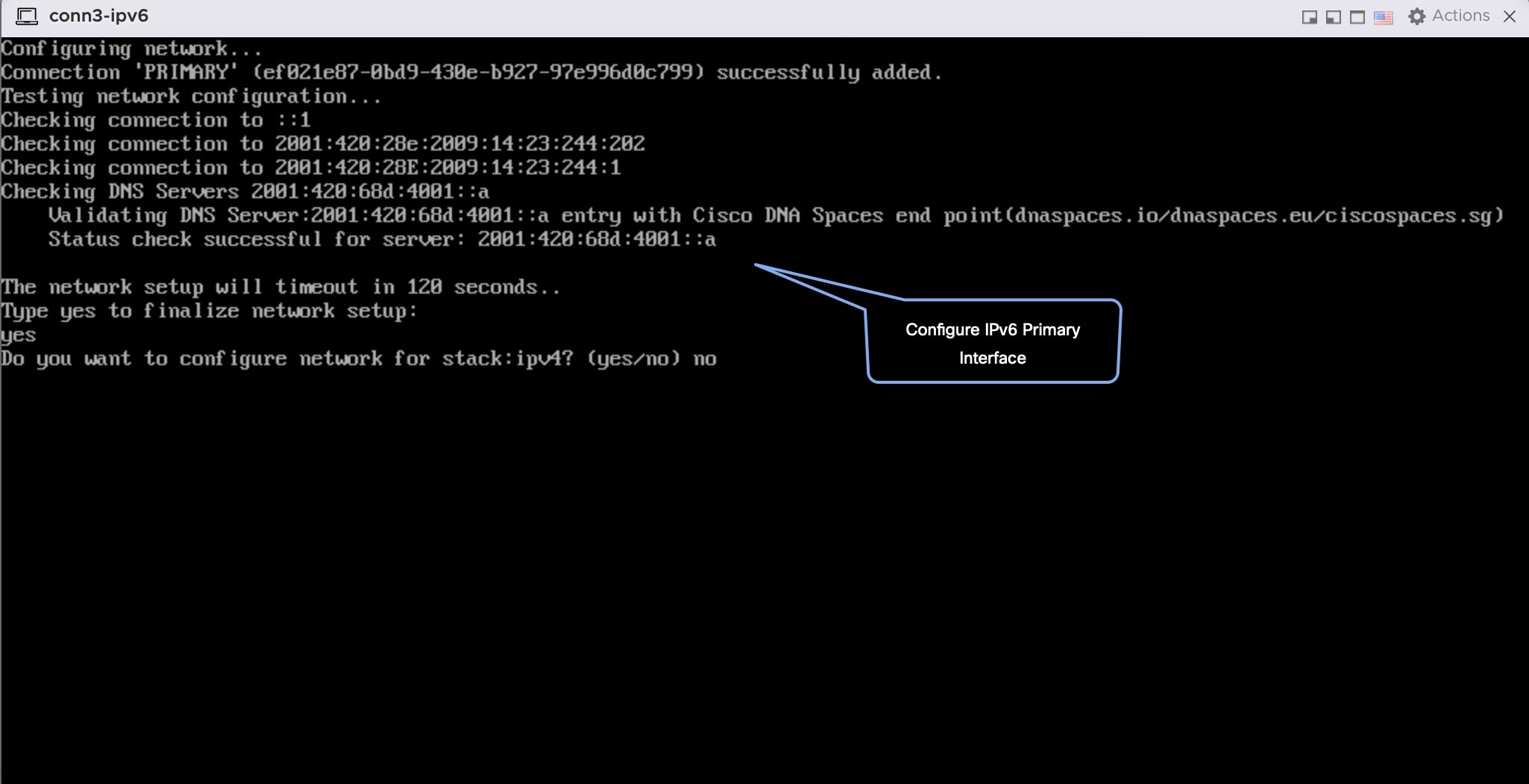
Figure 26. Configuring the Primary Interface: IPv6

Step 18

Do one of the following, and then configure the network settings for the PRIMARY interface. Specify parameters such as IP address, hostname, and so on.

  • Configure the IPv6 stack.
  • Configure the IPv4 stack.

You can add multiple DNS servers as a comma separated list in this step. After the task is complete and the Cisco Spaces: Connector is deployed, you can login to the connector CLI, and run the connectorctl network config command to add more DNS servers or edit the existing list.

Step 19

Confirm the setup.

Note


Because this configuration window times out in 120 seconds, ensure that you provide the input on time to avoid reconfiguration.

Step 20

Reset the password for the spacesadmin user.

Step 21

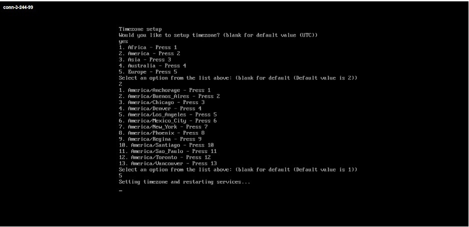
Enter the time zone.

Figure 27. Time Zone

Step 22

Enter the Network Time Protocol (NTP) server name to synchronize the system time with that of NTP server, or leave it blank if you do not want to configure an NTP server.

Figure 28. Configure NTP
Figure 29. Configure NTP

Step 23

Note the URL (https://connector-ip) before the automatic reboot. You can use this URL later to open the connector GUI.

Figure 30. ConnectorGUI