Overview
 Note |
Cisco DNA Spaces is now Cisco Spaces. We are in the process of updating our documentation with the new name. This includes updating GUIs and the corresponding procedures, screenshots, and URLs. For the duration of this activity, you might see occurrences of both Cisco DNA Spaces and Cisco Spaces. We take this opportunity to thank you for your continued support. |
Overview of IoT Service (Wired)
Cisco Spaces enables end-to-end wired and wireless IoT device management, monitoring, and business outcome delivery at an enterprise scale using the following:
-
Cisco Spaces: IoT Service
-
Cisco Spaces: IoT Device Marketplace
-
Cisco Spaces App Center
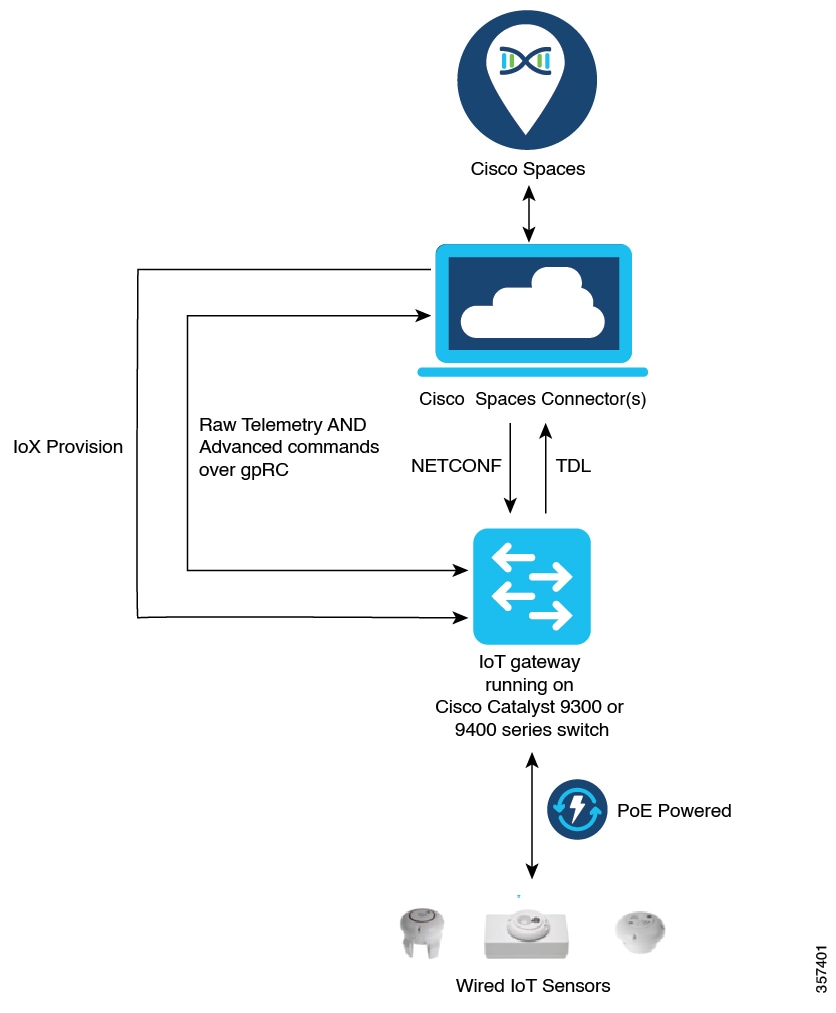
In addition to serving as the management hub for wireless IoT devices, IoT Service can now integrate with Cisco Catalyst 9300 and 9400 Series Switches from Release 17.3.3 or later to receive IoT service (wired) data from sensors, such as:
-
Passive infrared (PIR) sensors for presence detection
-
Temperature and humidity sensors
-
Smart lighting devices
-
Smart shades
-
Ethernet port status
-
Smart power distribution unit (PDU)
-
Hella Camera
Integrating IoT service (wired) with the Cisco Catalyst 9300 and 9400 Series Switches series platform requires the following:
-
Cisco Spaces: Connector
-
A IoT service (wired) gateway deployed and managed by Cisco Spaces
Cisco Catalyst 9300 and 9400 Series Switches can send critical IoT data to IoT service (wired). IoT service (wired) can then transmit the information to:
-
Business outcome applications on Cisco Spaces
-
Cisco Spaces App Center using the Firehose API
Compatibility Matrix for IoT Service (Wired)
|
Application Name |
Support for IoT Service (Wired) |
|---|---|
|
Cisco Spaces: Connector Docker |
2.0.455 and later |
|
Cisco Spaces: Connector OVA |
2.3 and later |
|
Cisco Prime Infrastructure |
Cisco Prime Infrastructure Release 3.8 MR1 |
|
Catalyst Center (for map import) |
Catalyst Center Release 2.1.1 and later |
|
Switch as a gateway |
Cisco IOS XE Amsterdam 17.3.x and later releases. |
|
Wired Application Version |
1.0.46 and later |
IoT service (wired) is not supported with Cisco Spaces tenants or deployments leveraging the following configurations:
- Connecting directly with controller
- CMX Tethering
Prerequisites for Cisco Spaces: IoT Service (Wired)
The following are the necessary prerequisites to get you started with Cisco Spaces: IoT Service (Wired):
-
Install Cisco Spaces: Connector in your network.
-
Configure a network with one or more Cisco Catalyst 9300 and 9400 Series Switches, Release 17.3.3 or later.
-
Switches must have Cisco DNA Advantage subscription.
-
Deploy wired sensors in your network. See Compatibility Matrix for IoT Service (Wired) .
-
Ensure that Cisco Spaces is configured with maps either from Cisco Prime Infrastructure or Catalyst Center.
-
Configure AAA on aCisco Catalyst 9300 Series Switches or a Cisco Catalyst 9400 Series Switches before adding it to Cisco Spaces by running these commands in:
-
aaa new-model
-
aaa authentication login default local
-
aaa authorization exec default local
-
-
Perform NTP synchronization across wireless controllers, Cisco Spaces: Connectors, and switches in the network.
-
Enable NETCONF on Cisco Catalyst 9300 or 9400 Series Switches on port 830, along with permission to use NETCONF.
Note
Cisco Catalyst 9300 and 9400 Series Switches require a local privilege level 15 user to use NETCONF. Additionally, the user must be a password-protected local user, because public-key authentication is not supported.
Design Prerequisites
Ensure you have the following information handy before proceeding:

-
Destination SPAN VLAN: The VLAN used to send Encapsulated Remote Switched Port Analyzer (ERSPAN) traffic from Power over Ethernet (PoE) nodes to Cisco IOx App. You can use an existing VLAN or create a new one. This VLAN can also be local to the switch.
-
Destination SPAN VLAN IP address: This is the Switched Virtual Interface (SVI) or the IP address of the destination VLAN that can be used to route traffic. If you are using an existing VLAN, you can provide the same IP address. We recommend that you create a new VLAN so that you can keep the ERSPAN traffic local without impacting the existing configuration. Note that this VLAN is used only within the switch for the SPAN traffic.
-
Source SPAN VLAN list: List of VLANs to which the wired devices are connected. The traffic on these VLANs are monitored. If the wired devices are connected to multiple VLANs, enter the VLANs separated by a comma.
-
Monitor SPAN origin IP address: This is the source IP address of the monitor session. This can be from the SPAN VLAN. This can also be the same as the destination VLAN IP address.
-
IoX application Span IP Address
-
Application Cisco Spaces Connector VLAN: This is the VLAN on which the connector is reachable (for management or data). You can configure the Cisco IOx App's second interface to use this VLAN to send traffic to the connector. This VLAN can be the same as the wired PoE node VLAN. The connector must be permitted to accept communications from the Cisco IOx application.
-
DHCP: When enabled, DHCP allocates an IP address from the Application DNA Spaces Connector VLAN to the Cisco IOx App's second interface.
-
IoX application IP address: This is the IP address that you must manually configure for the Cisco IOx App's second interface, and is used to communicate with the Connector. This is not required if you select DHCP.
-
IoX application netmask: This is the IP subnet mask that you must manually configure for the Cisco IOx App's second interface, and is used to communicate with the connector. This is not required if you select DHCP.
-
IoX application gateway address: This is the IP address that you must manually configure for the Cisco IOx App's second interface, and is used to communicate with the connector. This is not required if you select DHCP.

Prerequisites for Cisco Spaces: IoT Service (Wired)
The following are the necessary prerequisites to get you started with Cisco Spaces: IoT Service (Wired):
-
Install Cisco Spaces: Connector in your network.
-
Configure a network with one or more Cisco Catalyst 9300 and 9400 Series Switches, Release 17.3.3 or later.
-
Switches must have Cisco DNA Advantage subscription.
-
Deploy wired sensors in your network. See Compatibility Matrix for IoT Service (Wired) .
-
Ensure that Cisco Spaces is configured with maps either from Cisco Prime Infrastructure or Catalyst Center.
-
Configure AAA on aCisco Catalyst 9300 Series Switches or a Cisco Catalyst 9400 Series Switches before adding it to Cisco Spaces by running these commands in:
-
aaa new-model
-
aaa authentication login default local
-
aaa authorization exec default local
-
-
Perform NTP synchronization across wireless controllers, Cisco Spaces: Connectors, and switches in the network.
-
Enable NETCONF on Cisco Catalyst 9300 or 9400 Series Switches on port 830, along with permission to use NETCONF.
Note
Cisco Catalyst 9300 and 9400 Series Switches require a local privilege level 15 user to use NETCONF. Additionally, the user must be a password-protected local user, because public-key authentication is not supported.
Design Prerequisites
Ensure you have the following information handy before proceeding:
-
Destination SPAN VLAN: The VLAN used to send Encapsulated Remote Switched Port Analyzer (ERSPAN) traffic from Power over Ethernet (PoE) nodes to Cisco IOx App. You can use an existing VLAN or create a new one. This VLAN can also be local to the switch.
-
Destination SPAN VLAN IP address: This is the Switched Virtual Interface (SVI) or the IP address of the destination VLAN that can be used to route traffic. If you are using an existing VLAN, you can provide the same IP address. We recommend that you create a new VLAN so that you can keep the ERSPAN traffic local without impacting the existing configuration. Note that this VLAN is used only within the switch for the SPAN traffic.
-
Source SPAN VLAN list: List of VLANs to which the wired devices are connected. The traffic on these VLANs are monitored. If the wired devices are connected to multiple VLANs, enter the VLANs separated by a comma.
-
Monitor SPAN origin IP address: This is the source IP address of the monitor session. This can be from the SPAN VLAN. This can also be the same as the destination VLAN IP address.
-
IoX application Span IP Address
-
Application Cisco Spaces Connector VLAN: This is the VLAN on which the connector is reachable (for management or data). You can configure the Cisco IOx App's second interface to use this VLAN to send traffic to the connector. This VLAN can be the same as the wired PoE node VLAN. The connector must be permitted to accept communications from the Cisco IOx application.
-
DHCP: When enabled, DHCP allocates an IP address from the Application DNA Spaces Connector VLAN to the Cisco IOx App's second interface.
-
IoX application IP address: This is the IP address that you must manually configure for the Cisco IOx App's second interface, and is used to communicate with the Connector. This is not required if you select DHCP.
-
IoX application netmask: This is the IP subnet mask that you must manually configure for the Cisco IOx App's second interface, and is used to communicate with the connector. This is not required if you select DHCP.
-
IoX application gateway address: This is the IP address that you must manually configure for the Cisco IOx App's second interface, and is used to communicate with the connector. This is not required if you select DHCP.
Open Ports for IoT service (wired)
This section lists the connector ports that must be open for the proper functioning of each service or protocol.


| Primary IP Address | Disaster Recovery | |
|---|---|---|
| US Setup Type |
52.20.144.155 34.231.154.95 |
54.176.92.81 54.183.58.225 |
| EU Setup Type |
63.33.127.190 63.33.175.64 |
3.122.15.26 3.122.15.7 |
| Singapore Setup (SG) Type |
13.228.159.49 54.179.105.241 |
13.214.251.223 54.255.57.46 |
Configure IoT Service (Wired)
Procedure
|
Step 1 |
From the Cisco Spaces dashboard left-navigation pane, click Setup and choose Wired Networks. |
||
|
Step 2 |
From the Connect your wireless network window that is displayed, go to the Step 2 area and click View Connectors. 
|
||
|
Step 3 |
Click a connector 3 of your choice.
|
||
|
Step 4 |
In the connector details window that is displayed, click Add Services. 
|
||
|
Step 5 |
In the Add Service window that is displayed, choose IoT Wired and click Add. 
|
||
|
Step 6 |
Click the gear icon near the IoT Wired row. 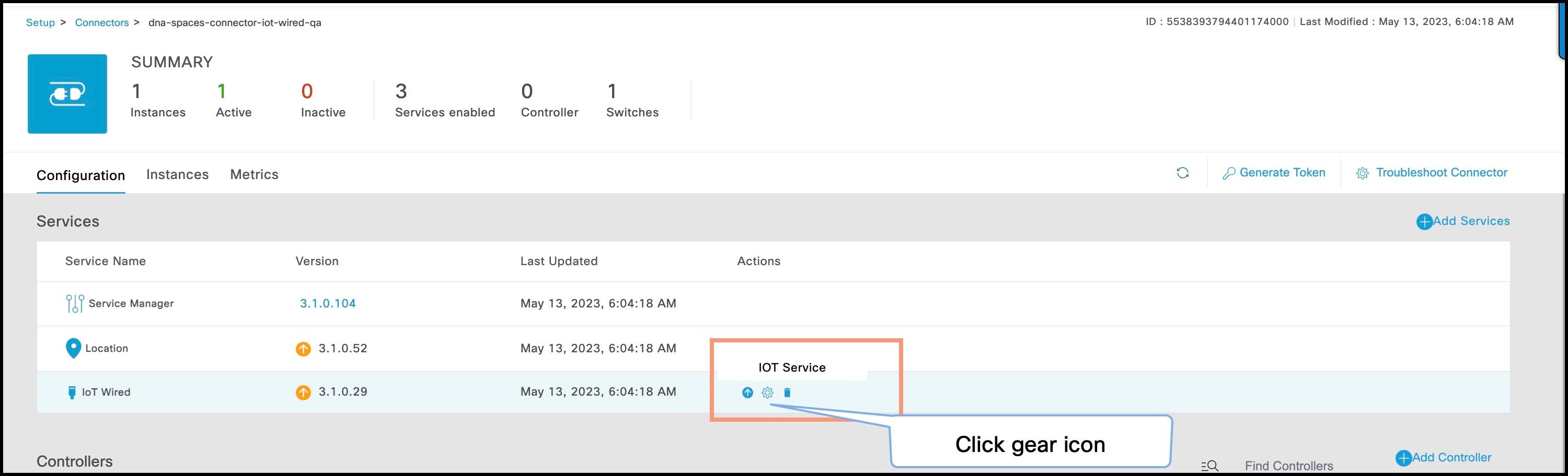
|
||
|
Step 7 |
(Optional) In the Manage IoT Streams window that is displayed, check if the connector is not already enabled, and if it is not, click Configure to Enable. |
||
|
Step 8 |
From the list of switches, click the vertical three-dot icon adjacent to the switch and select Enable Service. 
|
||
|
Step 9 |
Enter the SPAN VLAN and the Cisco IOx App details.


|
||
|
Step 10 |
Click Configure. 
|
||
|
Step 11 |
In the Manage IoT Services window that you are taken to, you can click on a name of the switch to see the list of steps executed on that switch. 
|
Verify if Cisco Catalyst 9300 and 9400 Series Switches are Added to the Connector
This procedure helps you verify if a Cisco Catalyst 9300 or 9400 Series Switches are deployed and active. This is a necessary prerequisite for proper functioning of Cisco Spaces: IoT Service (Wired).
Procedure
|
Step 1 |
In the Cisco Spaces dashboard left navigation pane, choose Setup > Wired Network. |
|
Step 2 |
In the Add Switch area, click View Switches. 
|
|
Step 3 |
Ensure that a switch is listed here, and is connected to a Cisco Spaces: Connector. 
|
 Feedback