3GPP RAN/NAS Cause Codes Support

Feature Summary and Revision History

Summary Data

Table 1. Summary Data

Applicable Product(s) or Functional Area

cnSGW-C

Applicable Platform(s)

SMI

Feature Default Setting

Enabled - Always-on

Related Documentation

Not Applicable

Revision History

Table 2. Revision History

Revision Details

Release

First introduced.

2021.02.0

Feature Description

cnSGW-C supports RAN/NAS cause codes as defined in 3GPP TS 29.274, version 15.4.0, section 8.103, RAN/NAS Cause.

cnSGW-C transparently transmits the RAN/NAS Release Cause IE provided by the MME to the PGW for further propagation towards the PCRF.


Note


GTP-based S5/S8 and S11 are supported.


The following table lists the RAN/NAS Cause codes.

Table 3. RAN/NAS Cause Codes

Octets

Bits

8

7

6

5

4

3

2

1

1

Type = 172 (decimal)

2–3

Length = n

4

Spare

Instance

5

Protocol Type

Cause Type

6 to m

Cause Value

(m+1) to (n+4)

One or more octets from these octets are present, only if explicitly specified

The Protocol Type field is encoded with the specified values for the RAN/NAS Cause as follows:

Table 4. Protocol Type

Protocol Type

Values (Decimal)

S1AP Cause

1

EMM Cause

2

ESM Cause

3

<spare>

4–15

The Cause Value field (and the associated RAN cause subcategory) is transferred over the S1-AP interface. The field is encoded in one octet as a binary integer.

Table 5. Cause Type

Cause Type

Values (Decimal)

Radio Network Layer

0

Transport Layer

1

NAS

2

Protocol

3

Miscellaneous

4

<spare>

5–15

For EMM and ESM Causes, the Cause Value field contains the cause value as specified in 3GPP TS 24.301. If the Protocol is S1AP, the cause value contains the specified value as in 3GPP TS 36.413.

How it Works

This section describes how this feature works.

Call Flows

This section describes the key call flows for the RAN/NAS Cause Codes feature.

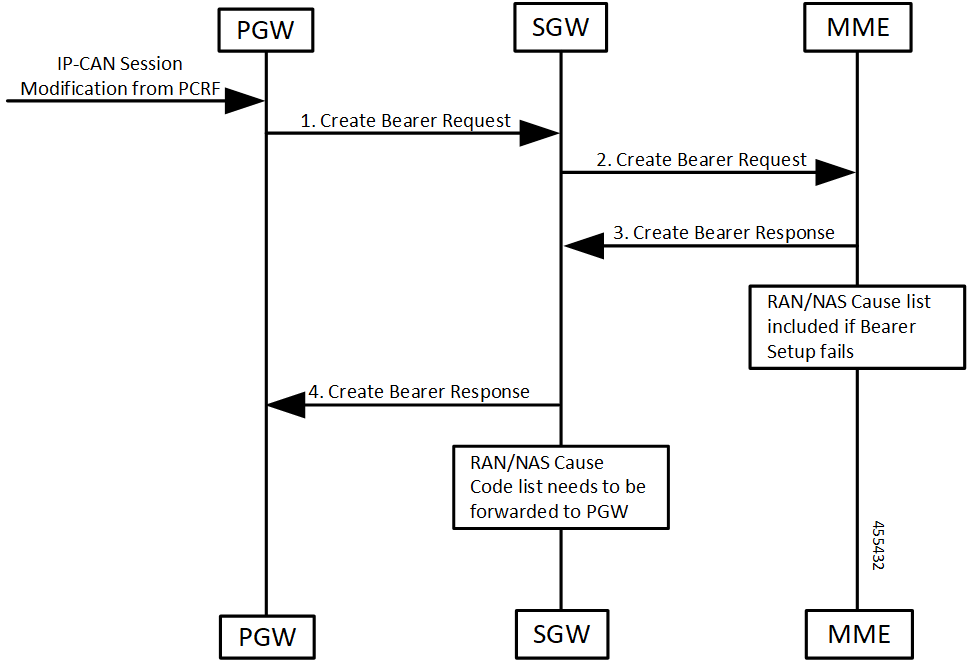
Create Bearer Procedure Call Flow

This section describes the create bearer procedure call flow.

Figure 1. Create Bearer Procedure Call Flow
Table 6. Create Bearer Procedure Call Flow Description

Step

Description

1

PGW receives IP-CAN session modification request from PCRF.

PGW creates the Create Bearer Request message and sends it to SGW (cnSGW-C).

2

SGW (cnSGW-C) forwards the Create Bearer Request message request to MME.

3

MME generates a Create Bearer Response message towards SGW (cnSGW-C).

If bearer setup fails, then the RAN/Cause list included in the response.

4

SGW (cnSGW-C) forwards the Create Bearer Response message to PGW.

It includes RAN/NAS Cause Code list.

Update Bearer Procedure Call Flow

This section describes the update bearer procedure call flow.

Figure 2. Update Bearer Procedure Call Flow
Table 7. Update Bearer Procedure Call Flow Description

Step

Description

1

PGW receives IP-CAN session modification request from PCRF.

PGW creates the Update Bearer Request message to SGW (cnSGW-C).

2

SGW (cnSGW-C) forwards the Update Bearer Request message to MME.

3

MME generates an Update Bearer Response message towards SGW (cnSGW-C).

If this bearer modification fails, then the RAN/NAS list included in the response.

4

SGW (cnSGW-C) forwards the Update Bearer Response message to PGW.

Delete Bearer Command Procedure Call Flow

This section describes the delete bearer command procedure call flow.

Figure 3. Delete Bearer Command Procedure Call Flow
Table 8. Delete Bearer Command Procedure Call Flow Description

Step

Description

1

MME receives an indication of Bearer Release from eNodeB request.

MME creates Delete Bearer Command message to SGW (cnSGW-C).

It includes RAN/NAS cause code list.

2

SGW (cnSGW-C) forwards the Delete Bearer Command message request to PGW.

It detects and forwards RAN/NAS cause code list.

3

PGW sends the Delete Bearer Request message to SGW (cnSGW-C).

PGW receives IP-CAN session modification request from PCEF.

4

SGW (cnSGW-C) generates a Delete Bearer Request message towards MME.

5

MME generates a Delete Bearer Response message towards SGW (cnSGW-C).

6

SGW (cnSGW-C) further sends the Delete Bearer Response message to PGW.

Delete Session Procedure Call Flow

This section describes the delete session procedure call flow.

Figure 4. Delete Session Procedure Call Flow
Table 9. Delete Session Procedure Call Flow Description

Step

Description

1

MME receives an indication of Cancel Location from HSS.

MME creates Delete Session Request message to SGW (cnSGW-C).

It includes RAN/NAS cause code list.

2

SGW (cnSGW-C) forwards the Delete Session Request message request to PGW.

It detects and forwards RAN/NAS cause code list.

3

PGW sends the Delete Session Response message to SGW (cnSGW-C).

PGW receives IP-CAN session modification request from PCEF.

4

SGW (cnSGW-C) generates a Delete Session Response message towards MME.