Cisco CRS Carrier Routing System 16-Slot Line Card Chassis Router Overview

This chapter includes the following sections:

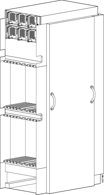
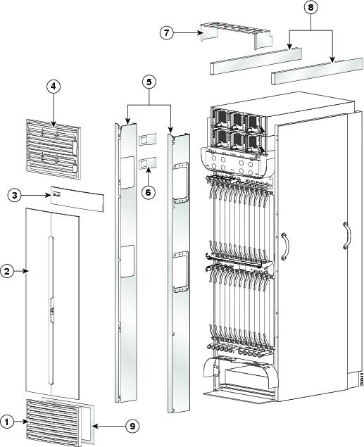
About the CRS 16-Slot Line Card Chassis

The 16 slots in the Cisco CRS 16-slot Line Card Chassis (LCC) can contain the following:

  • Modular services cards (MSCs)
  • Forwarding processor (FPs) cards
  • Label switch processor (LSP) cards

Note

MSCs, FPs, and LSPs are referred to as line cards.
  • Associated physical layer interface modules (PLIMs)
  • SPA Interface Processors (SIPs)

Each slot has the capacity of up to 200 gigabits per second (Gbps) ingress and 200 Gbps egress, for a total routing capacity per chassis of 6400 Gbps or 6.4 terabits per second (Tbps). (A terabit is 1 x 1012 bits or 1000 gigabits.)

The LCC supports 40G, 140G, and 400G fabric cards, as follows:

  • The Cisco CRS-1 Carrier Routing System uses fabric cards designed for 40 G operation (CRS-16-FC/S or CRS-16-FC/M cards).
  • The Cisco CRS-3 Carrier Routing System uses fabric cards designed for 140G operation (CRS-16-FC140/S or CRS-16-FC140/M cards).
  • The Cisco CRS-X Carrier Routing System uses fabric cards designed for 200G operation (CRS-16-FC400/S or CRS-16-FC400/M cards in 200G mode).

A mixture of 40G, 140G, and 400G fabric cards is not supported except during migration.


Note

Throughout this document, the generic term Cisco CRS Carrier Routing system refers to the Cisco CRS-1, Cisco CRS-3, and Cisco CRS-X Carrier Routing Systems, unless otherwise specified.

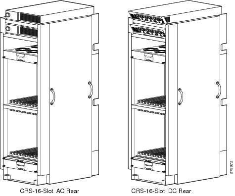
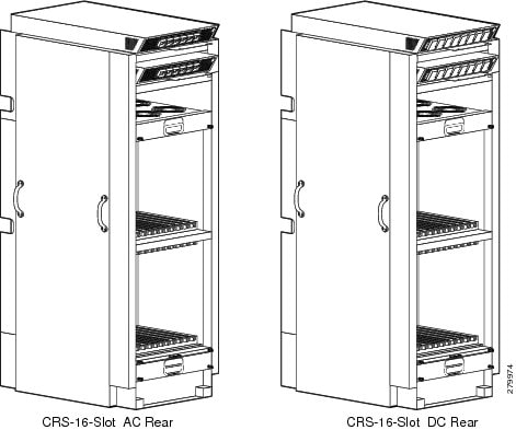
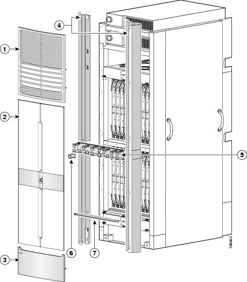
The chassis has an integrated rack and does not require an external rack. The chassis is bolted to the facility floor. It contains its own power and cooling systems. Two types of power systems are available: fixed and modular. Both power configurations use either AC or DC power.

This system description is not a planning, an installation, or a configuration guide.

Chassis Components

This section lists the main components of an LCC. It primarily identifies the components considered field-replaceable units (FRUs), but where additional detail is useful identifies subassemblies that are not field replaceable.

The LCC contains:

  • Up to 16 line cards, associated PLIMs, and SIPs/SPAs. A line card and a PLIM or SIP/SPA are an associated pair of cards that connect through the chassis midplane. The line card provides the forwarding engine for Layer 3 routing of user data that is switched through the system, and the PLIM or SIP/SPA provides the physical interface and connectors for the user data.

Note

For a complete list of available PLIMs, consult your Cisco sales representative or visit: http://www.cisco.com
    • The MSC card is available in the following versions: CRS-MSC (end-of-sale), CRS-MSC-B, CRS-MSC-140G, and CRS-MSC-X (200G mode).
    • The FP card is available in the following versions: CRS-FP140, CRS-FP-X and CRS-FP-X-L (200G mode).
    • The LSP card is: CRS-LSP.
  • Each line card can be associated with different types of PLIMs, which provide different interface speeds and technologies. Note the following:
    • The CRS-MSC-B card is compatible with both 40G CRS-1 and 140G CRS-3 fabric cards.
    • The CRS-MSC-140G card is only compatible with the 140G CRS-3 fabric card.
    • The CRS-MSC-X and CRS-MSC-L card (200G mode) is only compatible with the 400G CRS-X fabric card.
  • A chassis midplane. The midplane connects a line card to its associated PLIM. The midplane design allows the line card to be removed from the chassis without having to disconnect the cables that are attached to the associated PLIM. The midplane, which also distributes power, connects the line cards to the switch fabric cards, and provides control plane interconnections, is not field replaceable by the customer.
  • Two route processor (RP) cards. The RPs supply the intelligence of the system by functioning as the chassis system controller.

A Performance Route Processor (PRP) card is also available for the Cisco CRS 16-slot line card chassis. The PRPs perform the same functions as RPs, but provide enhanced performance for both route processing and system controller functionality.


Note

A chassis may not be populated with a mix of RP and PRP cards. Both route processor cards should be of the same type (RP or PRP).
  • Two fan controller cards. The cards control the speed of high-speed fans in the fan trays to adjust the airflow for ambient conditions.
  • Upper and lower fan trays. The trays push and pull air through the chassis. A removable air filter is located above the lower fan tray.
  • Eight switch fabric cards. These fabric cards provide a three-stage Benes switch fabric for the system.
    • As a single-shelf (standalone) system, the line card chassis contains S123 switch fabric cards that provide all three stages of the three-stage Benes switch fabric.
    • As part of a multishelf system, the LCC contains S13 fabric cards that provide stage 1 and stage 3 of the switch fabric. S2 fabric cards in the FCCs provide stage 2 of the fabric, and fabric cables connect the fabric cards to each other.

Caution

The LCC, when installed as part of a multishelf system, supports either 40 G fabric cards (CRS-16-FC/M cards), 140 G fabric cards (CRS-16-FC140/M cards), or 400G fabric cards (CRS-16-FC400/M cards in 200G mode). A LCC with a mix of 40G, 140G, and 400G fabric cards is not a supported mode of operation. Such a mode is allowed temporarily only during the upgrade process.


Caution

The LCC, when installed as a single-shelf (standalone) system, supports either 40G fabric cards (CRS-16-FC/S cards), 140G fabric cards (CRS-16-FC140/S cards), or 400G fabric cards (CRS-16-FC400/S cards). A LCC with a mix of 40G, 140G, and 400G fabric cards is not a supported mode of operation. Such a mode is temporarily allowed only during the upgrade process.


  • Two alarm modules. The alarm modules provide external alarm system connections. The alarm modules are located in the AC or DC power shelves.
  • Two types of power systems are available: fixed configuration power and modular configuration power. Both power configurations use either AC or DC power. Both Fixed and modular power support redundant power shelves and power modules.

The following figure shows a front view of a Cisco CRS 16-slot line card chassis with an AC fixed configuration power supply. The front view of a Cisco CRS 16-slot line card chassis with a DC fixed configuration power supply is similar.

Figure 1. Line Card Chassis Front (PLIM) Side View - Fixed Configuration Power

The following shows the rear view of a Cisco CRS 16-slot line card chassis with an AC and DC fixed configuration power supply.

Figure 2. Line Card Chassis Rear (MSC) Side View - Fixed Configuration Power

The following figure shows a front view of a Cisco CRS 16-slot line card chassis with an AC and DC modular configuration power supply.

Figure 3. Line Card Chassis Front (PLIM) Side View - Modular Configuration Power

The following figure shows the rear view of a Cisco CRS 16-slot line card chassis with an AC and DC modular configuration power supply.

Figure 4. Line Card Chassis Rear (MSC) Side View - Modular Configuration Power

System Architecture

Every Cisco CRS 16-slot line card chassis has 16 MSC, FC, or LSP slots, each with a capacity of up to 200 gigabits per second (Gbps) ingress and 200 Gbps egress, for a total routing capacity per chassis of 6400 Gbps or 6.4 terabits per second (Tbps). (A terabit is 1 x 1012 bits or 1000 gigabits.)

The routing system is built around a scalable, distributed three-stage Benes switch fabric and a variety of data interfaces. The data interfaces are contained on PLIMs that mate with an associated line card through the chassis midplane. The switch fabric cross-connects line cards to each other. The following figure is a simple diagram of the basic Cisco CRS routing system architecture.

Figure 5. Simple Cisco CRS Series Routing System Architecture

The figure illustrates the following concepts, which are common to all Cisco CRS routing systems:

  • Packet data enters the line card through physical data interfaces located on the associated PLIM. In the figure, these physical interfaces are represented by four OC-192 ports.
  • Data is routed through the line card, a Layer 3 forwarding engine, to the three-stage Benes switch fabric. Each line card and its associated PLIM have Layer 1 through Layer 3 functionality, and each line card can deliver line-rate performance (200 Gbps aggregate bandwidth). See Line Cards and Physical Layer Interface Modules for more information.
  • The three-stage Benes switch fabric cross-connects the line cards in the routing system. The switch fabric is partitioned into eight planes (plane 0 to plane 7) and is implemented by several components. See Switch Fabric for more information.

Main Features

The main features of all Cisco CRS Series routing systems include:

  • A highly scalable router that provides a routing capacity between 1.28 and 6.4 Tbps.
  • A wide range of interface speeds and types (for example, OC-48 packet-over-SONET (POS) and OC-192 POS), and a programmable MSC, FP, or LSP forwarding engine that provides full-featured forwarding at line-rate speeds.
  • Redundancy and reliability features allow nonstop operation even during service upgrades of equipment, with no single points of failure in hardware or software.
  • Potential for expanding from single-chassis to multichassis (or multishelf) systems.
  • Partitioning into logical routers. A logical router (LR) is a set of line cards and route processors (RPs) that form a complete router. More specifically, each LR contains its own instance of dynamic routing, IP stack, SysDB (system database), interface manager, event notification system, and so on.

Chassis Overview

The Cisco CRS Series 16-slot line card chassis is the mechanical enclosure that contains the system components. The line card chassis is secured to the floor and has a locking front and optional rear doors. The line card chassis is a complete rack enclosed in a cabinet. A single-shelf (standalone) system consists of a single line card chassis only. A multishelf system consists of up to nine line cards and connects up to four switch fabric cards.

This section includes the following topics:

Chassis Slot Numbers

This section identifies the location and slot numbers for major cards and modules (primarily the field-replaceable units) that plug into the chassis.

The following figure shows the slot numbering on the front (PLIM) side of the Cisco CRS 16-slot line card chassis.

Figure 6. Line Card Chassis Slot Numbering—(PLIM Side)

As shown in the above figure, the Cisco CRS 16-slot line card chassis numbers on the PLIM side of the chassis include the card cage with:

  • Top power shelf (PS0)
  • Lower power shelf (PS1)
  • Upper PLIM card cage, left to right, eight PLIM slots (0, 1, 2, 3 and 4, 5, 6, 7) around two double-width fan controller card slots (FC0, FC1)
  • Lower PLIM card cage, left to right, eight PLIM slots (8, 9, 10, 11 and 12, 13, 14, 15) around two double-width route processor card slots (RP0, RP1)

The figure below shows the slot numbers on the rear (MSC) side of the Cisco CRS 16-slot line card chassis.

Figure 7. Line Card Slot Numbers—Rear (MSC Side)

As shown in the above figure, the components on the rear (MSC) side of the 16-slot chassis include:

  • Top fan tray (FT0)
  • Upper MSC-switch fabric card cage, eight line card slots (7, 6, 5, 4, and 3, 2, 1, 0) around four switch fabric card slots (SM0, SM1, SM2, and SM3)
  • Lower MSC-switch fabric card cage, eight line card slots (15, 14, 13, 12 and 11, 10, 9, 8) around four switch fabric card slots (SM4, SM5, SM6, and SM7)
  • Lower fan tray (FT1)

The MSC slot numbers are reversed from the PLIM slot numbers on the other side of the chassis. Because an MSC is associated and actually mates through the midplane with a PLIM, MSC slot 0 is on the far right side of the chassis looking at it from the rear (MSC) side; PLIM slot 0 is on the far left side of the chassis looking at it from the front (PLIM) side. MSC slot 0 and PLIM slot 0 mate with each other through the midplane, and so do all other MSC and PLIM slots (2 through 15).

Chassis Footprint

The following figure is a top view of the line card chassis footprint (with optional front and rear cosmetics installed).

Figure 8. Top View of CRS 16-Slot Line Card Chassis

1

40.2 in. (102.2 cm)

2

38.3 in. (97.2 cm)

3

32.8 in. (83.2 cm)

4

23.5 in. (59.8 cm)

The dimensions listed in the figure show the:

  • Depth of the line card chassis with the doors attached and closed, which is 40.2 in. (102.2 cm).
  • Depth of the front cable management to the rear cable management, excluding the doors, which is 38.3 in. (97.2 cm).
  • Distance from the front surface to the rear surface of the chassis, excluding cable management and the doors, which is 32.8 in. (83.2 cm).
  • Width of the chassis, which is 23.5 in. (59.8 cm).

Note

Because there is no external switch-fabric interconnection cabling on the single line card chassis system, the rear door is optional.

Cable Management

The Cisco CRS 16-slot line card chassis has cable management features for both the front (PLIM) and rear (MSC) sides of the chassis. The PLIM side has horizontal cable management features above both card cages. The horizontal cable management trays have a special telescoping feature that allows them to be extended when the chassis is upgraded with higher-density cards. This extension feature also helps when installing the cables in the chassis.


Note

The front doors need to be removed from the chassis when the telescoping feature is in use.

The MSC side of the chassis has one cable management system above the lower card cage (in the middle of the chassis). These cable management trays are not telescoping because there is a preset amount of fiber cabling to be managed.

Chassis Exterior Components

This section contains information about the exterior cosmetic components.

The Cisco CRS 16 slot line card chassis is shipped with exterior cosmetic components for the front (PLIM) side and rear (MSC) side of the chassis.


Note

Some exterior cosmetic components are not required to be installed.

The following figure shows the exterior cosmetics for the front (PLIM) side of a chassis with fixed configuration power shelves installed. The front view of a Cisco CRS 16-slot line card chassis with modular configuration power shelves installed is similar.

Figure 9. Front (PLIM) Side Exterior Cosmetic Components—Fixed Configuration Shown

1

Lower grille

6

Power shutoff extenders (fixed configuration power only)

2

Doors

7

Upper grille support

3

Logo bezel

8

Unistruts

4

Upper grille

9

Lower grille frame

5

Vertical cable troughs

The following figure shows the exterior cosmetics on the rear (MSC) side of a Cisco CRS 16-slot line card chassis, with fixed configuration power shelves installed. The upper air grille and vertical brackets are shipped with the Cisco CRS 16 slot line card chassis, but are not pre-installed on the system the system. The rear view of a Cisco CRS 16-slot line card chassis with modular configuration power shelves installed is similar.

Figure 10. Rear (MSC) Side Exterior Cosmetic Components—Fixed Configuration Shown

1

Upper air grille

3

Rear kick panel kit

2

Vertical brackets

The following figure shows the exterior cosmetics for the rear (MSC) side of an optional multi chassis system with fixed configuration power shelves installed. The rear view of an optional multi chassis system with modular configuration power shelves installed is similar.

Figure 11. Rear (MSC) Side Exterior Cosmetic Components—Optional Multi Chassis System

1

Upper air grille

5

Midchassis horizontal cable management bracket

2

Doors

6

Strike tube

3

Lower chassis cosmetic bezel

7

Door stop

4

Vertical cable troughs

Hardware Compatibility

The following table lists the compatibility of 40G CRS, 140G CRS, and 400G CRS fabric, forwarding, and line card components for the CRS 16-slot system.


Note

A router with a mix of 40G, 140G, and 400G fabric cards is not a supported mode of operation. Such a mode is temporarily allowed only during the upgrade process.
Table 1. CRS Compatibility Matrix

Switch Fabric

RP/DRP

MSC/FP/LSP

PLIMs

CRS-16-FC/S

RP-A (CRS-16-RP), RP-B (CRS-16-RP-B), DRP-B (CRS-DRP-B)

CRS-MSC-B

1OC768-DPSK/C 1OC768-ITU/C 1OC768-POS-SR 4-10GE-ITU/C 8-10GBE CRS1-SIP-800 4-10GE 42-1GE 20-1GE-FLEX 2-10GE-WL-FLEX 4-10GBE-WL-XFP 8-10GBE-WL-XFP

CRS-16-FC140/S

RP-A (CRS-16-RP), RP-B (CRS-16-RP-B), DRP-B (CRS-DRP-B)

CRS-MSC-B

1OC768-DPSK/C 1OC768-ITU/C 1OC768-POS-SR 4-10GE-ITU/C 8-10GBE CRS1-SIP-800 4-10GE 42-1GE 20-1GE-FLEX 2-10GE-WL-FLEX 4-10GBE-WL-XFP 8-10GBE-WL-XFP

CRS-16-FC140/S

PRP (CRS-16-PRP-6G, CRS-16-PRP-12G)

CRS-MSC-140G

1OC768-DPSK/C 1OC768-ITU/C 1OC768-POS-SR 4-10GE-ITU/C 8-10GBE CRS1-SIP-800 4-10GE 42-1GE 20-1GE-FLEX 2-10GE-WL-FLEX 4-10GBE-WL-XFP 8-10GBE-WL-XFP14X10GBE-WL-XFP 20X10GBE-WL-XFP 1x100GBE

CRS-16-FC140/S

PRP (CRS-16-PRP-6G, CRS-16-PRP-12G))

CRS-FP140

1OC768-DPSK/C 1OC768-ITU/C 1OC768-POS-SR 4-10GE-ITU/C 8-10GBE CRS1-SIP-800 4-10GE 42-1GE 2-10GE-WL-FLEX 4-10GBE-WL-XFP 8-10GBE-WL-XFP14X10GBE-WL-XFP 20X10GBE-WL-XFP 1x100GBE

CRS-16-FC140/S

PRP (CRS-16-PRP-6G, CRS-16-PRP-12G)

CRS-LSP

1OC768-DPSK/C 1OC768-ITU/C 1OC768-POS-SR 4-10GE-ITU/C 8-10GBE CRS1-SIP-800 4-10GE 42-1GE 20-1GE-FLEX 2-10GE-WL-FLEX 4-10GBE-WL-XFP 8-10GBE-WL-XFP14X10GBE-WL-XFP 20X10GBE-WL-XFP 1x100GBE

CRS-16-FC400/S

PRP (CRS-16-PRP-6G, CRS-16-PRP-12G)

CRS-MSC-X and CRS-MSC-X-=L (200G)

4x100GE-LO 40x10GE-WLO2x100GE-FLEX40

CRS-FP-X and CRS-FP-X-L (200G)

CRS-LSP