- About this Guide
- Chapter 1, Install Shelf and Backplane Hardware
- Chapter 2, Install Cards and Fiber-Optic Cable
- Chapter 3, Set Up PC and Log Into the GUI
- Chapter 4, Turn Up Node
- Chapter 5, Turn Up DWDM Node
- Chapter 6, Turn Up Network
- Chapter 7, Turn Up DWDM Network
- Chapter 8, Create Circuits and VT Tunnels
- Chapter 9, Manage Alarms
- Chapter 10, Monitor Performance
- Chapter 11, Manage Circuits
- Chapter 12, Change Node Settings
- Chapter 13, Change Card Settings
- Chapter 14, Upgrade Cards and Spans
- Chapter 15, Convert Network Configurations
- Chapter 16, Add and Remove Nodes
- Chapter 17, Maintain the Node
- Chapter 18, Power Down Node
- Appendix A, CTC Information and Shortcuts
- Appendix B, Specifications
Add and Remove Nodes
This chapter explains how to add and remove Cisco ONS 15454 nodes from bidirectional line switched rings (BLSRs), path protection, and linear add/drop multiplexers (ADMs).

Note ![]() The terms "Unidirectional Path Switched Ring" and "UPSR" may appear in Cisco literature. These terms do not refer to using Cisco ONS 15xxx products in a unidirectional path switched ring configuration. Rather, these terms, as well as "Path Protected Mesh Network" and "PPMN," refer generally to Cisco's path protection feature, which may be used in any topological network configuration. Cisco does not recommend using its path protection feature in any particular topological network configuration.
The terms "Unidirectional Path Switched Ring" and "UPSR" may appear in Cisco literature. These terms do not refer to using Cisco ONS 15xxx products in a unidirectional path switched ring configuration. Rather, these terms, as well as "Path Protected Mesh Network" and "PPMN," refer generally to Cisco's path protection feature, which may be used in any topological network configuration. Cisco does not recommend using its path protection feature in any particular topological network configuration.
Before You Begin
Before performing any of the following procedures, complete the "NTP-A195 Document Existing Provisioning" procedure on page 9-2. Also investigate all alarms and clear any trouble conditions. Refer to the Cisco ONS 15454 Troubleshooting Guide as necessary.
This section lists the chapter procedures (NTPs). Turn to a procedure for applicable tasks (DLPs).
1. ![]() A212 Add a BLSR Node—Complete as needed.
A212 Add a BLSR Node—Complete as needed.
2. ![]() A213 Remove a BLSR Node—Complete as needed.
A213 Remove a BLSR Node—Complete as needed.
3. ![]() A105 Add a Path Protection Node—Complete as needed.
A105 Add a Path Protection Node—Complete as needed.
4. ![]() A106 Remove a Path Protection Node—Complete as needed.
A106 Remove a Path Protection Node—Complete as needed.
5. ![]() A262 Add a Node to a Linear ADM—Complete as needed.
A262 Add a Node to a Linear ADM—Complete as needed.
6. ![]() A263 Remove a Node from a Linear ADM—Complete as needed.
A263 Remove a Node from a Linear ADM—Complete as needed.
NTP-A212 Add a BLSR Node
Purpose |
This procedure expands a BLSR by adding a node. |
Tools/Equipment |
Fiber for new node connections |
Prerequisite Procedures |
Cards must be installed and node turn-up procedures completed on the node that will be added to the BLSR. See Chapter 2, "Install Cards and Fiber-Optic Cable," and Chapter 4, "Turn Up Node." |
Required/As Needed |
As needed |
Onsite/Remote |
Onsite |
Security Level |
Provisioning or higher |

Step 1 ![]() Draw a diagram of the BLSR where you will add the node. In the diagram, identify the east and west BLSR OC-N trunk (span) cards that will connect to the new node. This information is essential to complete this procedure without error. Figure 16-1 shows a drawing of a three-node, two-fiber BLSR that uses Slots 5 and 12 for the BLSR trunk cards. The dashed arrow shows the new fiber connections that will be made to add the fourth node to the BLSR.
Draw a diagram of the BLSR where you will add the node. In the diagram, identify the east and west BLSR OC-N trunk (span) cards that will connect to the new node. This information is essential to complete this procedure without error. Figure 16-1 shows a drawing of a three-node, two-fiber BLSR that uses Slots 5 and 12 for the BLSR trunk cards. The dashed arrow shows the new fiber connections that will be made to add the fourth node to the BLSR.
Figure 16-1 Three-Node, Two-Fiber BLSR Before a Fourth Node Is Added
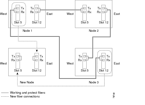
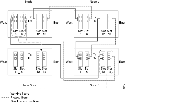
Figure 16-2 shows a sample drawing of a four-fiber BLSR. The dashed arrow shows the new fiber connections that will be made to add the fourth node. For four-fiber BLSRs, two fiber sets will be reconnected, the working fiber and the protect fiber.
Figure 16-2 Three-Node, Four-Fiber BLSR Before a Fourth Node is Added
Step 2 ![]() According to local site practice, complete the "NTP-A108 Back Up the Database" procedure on page 17-7 for all the nodes in the ring.
According to local site practice, complete the "NTP-A108 Back Up the Database" procedure on page 17-7 for all the nodes in the ring.
Step 3 ![]() Verify the card installation on the new node using the "NTP-A24 Verify Card Installation" procedure on page 4-2. Verify that the OC-N cards that will be the BLSR trunk cards match the BLSR optical rate. For example, if the BLSR is OC-48, the new node must have OC-48 cards installed. If the OC-N cards are not installed or the optical rates do not match the BLSR, complete the "NTP-A16 Install the OC-N Cards" procedure on page 2-12.
Verify the card installation on the new node using the "NTP-A24 Verify Card Installation" procedure on page 4-2. Verify that the OC-N cards that will be the BLSR trunk cards match the BLSR optical rate. For example, if the BLSR is OC-48, the new node must have OC-48 cards installed. If the OC-N cards are not installed or the optical rates do not match the BLSR, complete the "NTP-A16 Install the OC-N Cards" procedure on page 2-12.
Step 4 ![]() Verify that fiber is available to connect the new node to the existing nodes. Refer to the diagram drawn in Step 1.
Verify that fiber is available to connect the new node to the existing nodes. Refer to the diagram drawn in Step 1.
Step 5 ![]() Complete the "NTP-A35 Verify Node Turn Up" procedure on page 6-2. In order to have CTC visibility to the new node after it is added, you must be an authorized user on the node and you must have IP connectivity to the node.
Complete the "NTP-A35 Verify Node Turn Up" procedure on page 6-2. In order to have CTC visibility to the new node after it is added, you must be an authorized user on the node and you must have IP connectivity to the node.
Step 6 ![]() Create a static route on the new node if the following conditions are present. If the conditions are not present, continue with Step 7.
Create a static route on the new node if the following conditions are present. If the conditions are not present, continue with Step 7.
•![]() The IP address for the new node is on the same subnet as other nodes in the network.
The IP address for the new node is on the same subnet as other nodes in the network.
•![]() On the new node Provisioning > Network > General subtab, Craft Access Only is not checked under Gateway Settings.
On the new node Provisioning > Network > General subtab, Craft Access Only is not checked under Gateway Settings.
•![]() A CTC computer is directly connected to the new node.
A CTC computer is directly connected to the new node.
•![]() CTC computers are directly connected to other nodes on the same subnet.
CTC computers are directly connected to other nodes on the same subnet.
If these conditions are present, add static routes on the node that will be added to the BLSR, using the following settings:
•![]() Destination IP address: IP-address-of-the-CTC-computer-connected-to-the-new-node
Destination IP address: IP-address-of-the-CTC-computer-connected-to-the-new-node
•![]() Net Mask: 255.255.255.255
Net Mask: 255.255.255.255
•![]() Next Hop: IP-address-of-the-Cisco-ONS-15454
Next Hop: IP-address-of-the-Cisco-ONS-15454
•![]() Cost: 1
Cost: 1
See the "DLP-A65 Create a Static Route" task on page 4-15. To view Gateway Settings, see the "DLP-A249 Provision IP Settings" task on page 4-10.
Step 7 ![]() Complete the "DLP-A60 Log into CTC" task on page 3-24 at a node in the BLSR.
Complete the "DLP-A60 Log into CTC" task on page 3-24 at a node in the BLSR.
Step 8 ![]() Complete the "DLP-A298 Check the Network for Alarms and Conditions" task on page 15-3 to verify that the BLSR is free of major alarms or problems. If trouble is indicated (for example, a major alarm exists), resolve the problem before proceeding. See Chapter 9, "Manage Alarms" or, if necessary, refer to the Cisco ONS 15454 Troubleshooting Guide.
Complete the "DLP-A298 Check the Network for Alarms and Conditions" task on page 15-3 to verify that the BLSR is free of major alarms or problems. If trouble is indicated (for example, a major alarm exists), resolve the problem before proceeding. See Chapter 9, "Manage Alarms" or, if necessary, refer to the Cisco ONS 15454 Troubleshooting Guide.
Step 9 ![]() From the View menu, choose Go to Network View and click the Provisioning > BLSR tabs.
From the View menu, choose Go to Network View and click the Provisioning > BLSR tabs.
Step 10 ![]() On paper, record the Ring Name, Ring Type, Line Rate, Ring Reversion, and Span Reversion (4 Fiber).
On paper, record the Ring Name, Ring Type, Line Rate, Ring Reversion, and Span Reversion (4 Fiber).
Step 11 ![]() From the Nodes column, record the Node IDs in the BLSR. The Node IDs are the numbers in parentheses next to the node name.
From the Nodes column, record the Node IDs in the BLSR. The Node IDs are the numbers in parentheses next to the node name.
Step 12 ![]() Log into the new node:
Log into the new node:
•![]() If the node has a LAN connection and appears on the network map, from the View menu, choose Go to Other Node, then enter the new node.
If the node has a LAN connection and appears on the network map, from the View menu, choose Go to Other Node, then enter the new node.
•![]() If the new node is not connected to the network, log into it using the "DLP-A60 Log into CTC" task on page 3-24.
If the new node is not connected to the network, log into it using the "DLP-A60 Log into CTC" task on page 3-24.
Step 13 ![]() Click the Alarms tab. Verify that no critical or major alarms are present, nor any facility alarms, such as LOS, LOF, AIS-L, SF, and SD. If trouble is indicated (for example, a major alarm exists), resolve the problem before proceeding. See the Cisco ONS 15454 Troubleshooting Guide, as necessary.
Click the Alarms tab. Verify that no critical or major alarms are present, nor any facility alarms, such as LOS, LOF, AIS-L, SF, and SD. If trouble is indicated (for example, a major alarm exists), resolve the problem before proceeding. See the Cisco ONS 15454 Troubleshooting Guide, as necessary.
Step 14 ![]() Using the information recorded in Steps 10 and 11 and the diagram created in Step 1, create a BLSR on the new node. See the "DLP-A242 Create a BLSR on a Single Node" task.
Using the information recorded in Steps 10 and 11 and the diagram created in Step 1, create a BLSR on the new node. See the "DLP-A242 Create a BLSR on a Single Node" task.
Step 15 ![]() (Optional) Create test circuits, making sure they pass through the BLSR trunk cards, and run test traffic through the node to ensure the cards are functioning properly. See the "NTP-A189 Create a Manually Routed OC-N Circuit" procedure on page 8-47 and the "NTP-A62 Test OC-N Circuits" procedure on page 8-54 for information.
(Optional) Create test circuits, making sure they pass through the BLSR trunk cards, and run test traffic through the node to ensure the cards are functioning properly. See the "NTP-A189 Create a Manually Routed OC-N Circuit" procedure on page 8-47 and the "NTP-A62 Test OC-N Circuits" procedure on page 8-54 for information.
Step 16 ![]() Create the data communications channel (DCC) terminations on the new node. See the "DLP-A354 Provision SONET DCC Terminations" task on page 6-4.
Create the data communications channel (DCC) terminations on the new node. See the "DLP-A354 Provision SONET DCC Terminations" task on page 6-4.
Note ![]() Creating the DCC terminations causes the SDCC Termination Failure and Loss of Signal alarms to appear. These alarms remains active until you connect the node to the BLSR.
Creating the DCC terminations causes the SDCC Termination Failure and Loss of Signal alarms to appear. These alarms remains active until you connect the node to the BLSR.
Note ![]() If you map the K3 byte to another byte (such as E2), you must remap the line cards on either side of the new node to the same byte. See the "DLP-A89 Remap the K3 Byte" task on page 6-18.
If you map the K3 byte to another byte (such as E2), you must remap the line cards on either side of the new node to the same byte. See the "DLP-A89 Remap the K3 Byte" task on page 6-18.
Step 17 ![]() Complete the "DLP-A60 Log into CTC" task on page 3-24 at a BLSR node that will connect to the new node.
Complete the "DLP-A60 Log into CTC" task on page 3-24 at a BLSR node that will connect to the new node.
Step 18 ![]() Referring to the diagram created in Step 1, complete the "DLP-A303 Initiate a BLSR Force Ring Switch" task on the node that will connect to the new node on its west line (port). In the Figure 16-2 example, the BLSR force ring would occur at Node 1, West line (Slot 5 and 6).
Referring to the diagram created in Step 1, complete the "DLP-A303 Initiate a BLSR Force Ring Switch" task on the node that will connect to the new node on its west line (port). In the Figure 16-2 example, the BLSR force ring would occur at Node 1, West line (Slot 5 and 6).
Step 19 ![]() Referring to the diagram created in Step 1, complete the "DLP-A303 Initiate a BLSR Force Ring Switch" task on the node that will connect to the new node on its east line (port). In the Figure 16-2 example, the BLSR force ring would occur at Node 3, East line (Slot 12 and 13).
Referring to the diagram created in Step 1, complete the "DLP-A303 Initiate a BLSR Force Ring Switch" task on the node that will connect to the new node on its east line (port). In the Figure 16-2 example, the BLSR force ring would occur at Node 3, East line (Slot 12 and 13).
Step 20 ![]() Click the Alarms tab.
Click the Alarms tab.
a. ![]() Verify that the alarm filter is not on. See the "DLP-A227 Disable Alarm Filtering" task on page 9-32 as necessary.
Verify that the alarm filter is not on. See the "DLP-A227 Disable Alarm Filtering" task on page 9-32 as necessary.
b. ![]() Verify that no unexplained alarms appear on the network. If alarms appear, investigate and resolve them before continuing. Refer to the Cisco ONS 15454 Troubleshooting Guide for procedures.
Verify that no unexplained alarms appear on the network. If alarms appear, investigate and resolve them before continuing. Refer to the Cisco ONS 15454 Troubleshooting Guide for procedures.
Step 21 ![]() Following the diagram created in Step 1, remove the fiber connections from the two nodes that will connect to the new node.
Following the diagram created in Step 1, remove the fiber connections from the two nodes that will connect to the new node.
a. ![]() Remove the west fiber from the node that will connect to the east port of the new node. In the Figure 16-1 example, this is Node 1, Slot 5, and in Figure 16-2 this is Node 1, Slots 5 and 6.
Remove the west fiber from the node that will connect to the east port of the new node. In the Figure 16-1 example, this is Node 1, Slot 5, and in Figure 16-2 this is Node 1, Slots 5 and 6.
b. ![]() Remove the east fiber from the node that will connect to the west port of the new node. In the Figure 16-1 example, this is Node 3, Slot 12, and in Figure 16-2 this is Node 3, Slots 12 and 13.
Remove the east fiber from the node that will connect to the west port of the new node. In the Figure 16-1 example, this is Node 3, Slot 12, and in Figure 16-2 this is Node 3, Slots 12 and 13.
Step 22 ![]() Connect fibers from the adjacent nodes to the new node following the diagram created in Step 1. Connect the west port to the east port and the east port to the west port. For four-fiber BLSRs, connect the protect fibers.
Connect fibers from the adjacent nodes to the new node following the diagram created in Step 1. Connect the west port to the east port and the east port to the west port. For four-fiber BLSRs, connect the protect fibers.
Step 23 ![]() After the newly added node appears in network view, double-click it to display the node in node view.
After the newly added node appears in network view, double-click it to display the node in node view.
Step 24 ![]() Click the Provisioning > BLSR tabs.
Click the Provisioning > BLSR tabs.
Step 25 ![]() Click Ring Map. Verify that the new node appears on the Ring Map with the other BLSR nodes, then click OK.
Click Ring Map. Verify that the new node appears on the Ring Map with the other BLSR nodes, then click OK.
Step 26 ![]() From the View menu, choose Go to Network View and check the following:
From the View menu, choose Go to Network View and check the following:
a. ![]() Click the Provisioning > BLSR tabs. Verify that the new node appears under the Node column.
Click the Provisioning > BLSR tabs. Verify that the new node appears under the Node column.
b. ![]() Click the Alarms tab. Verify that BLSR alarms such as RING MISMATCH, E-W MISMATCH, PRC-DUPID (duplicate node ID), and APSCDFLTK (default K) do not appear.
Click the Alarms tab. Verify that BLSR alarms such as RING MISMATCH, E-W MISMATCH, PRC-DUPID (duplicate node ID), and APSCDFLTK (default K) do not appear.
If the new node does not appear in the Node column, or if BLSR alarms are present, log into the new node and verify that the BLSR is provisioned on it correctly with the information from Steps 10 and 11. If the node still does not appear, or if alarms persist, refer to the Cisco ONS 15454 Troubleshooting Guide.
Step 27 ![]() Click the Circuits tab. Wait until all the circuits are discovered. The circuits that pass through the new node will be shown as incomplete.
Click the Circuits tab. Wait until all the circuits are discovered. The circuits that pass through the new node will be shown as incomplete.
Note ![]() If the circuits take more than a minute to appear, log out of CTC, then log back in.
If the circuits take more than a minute to appear, log out of CTC, then log back in.
Step 28 ![]() In network view, right-click the new node and choose Update Circuits With The New Node from the shortcut menu. Verify that the number of updated circuits in the dialog box is correct.
In network view, right-click the new node and choose Update Circuits With The New Node from the shortcut menu. Verify that the number of updated circuits in the dialog box is correct.
Step 29 ![]() If incomplete circuits are still present, refer to the Cisco ONS 15454 Troubleshooting Guide.
If incomplete circuits are still present, refer to the Cisco ONS 15454 Troubleshooting Guide.
Step 30 ![]() Click the History tab. Verify that BLSR_RESYNC conditions appear for every node in the BLSR.
Click the History tab. Verify that BLSR_RESYNC conditions appear for every node in the BLSR.
Step 31 ![]() Complete the "DLP-A194 Clear a BLSR Force Ring Switch" task to remove the ring switch from the east and west BLSR lines.
Complete the "DLP-A194 Clear a BLSR Force Ring Switch" task to remove the ring switch from the east and west BLSR lines.
Step 32 ![]() According to local site practice, complete the "NTP-A175 Two-Fiber BLSR Acceptance Test" procedure on page 6-22 or the "NTP-A176 Four-Fiber BLSR Acceptance Test" procedure on page 6-30.
According to local site practice, complete the "NTP-A175 Two-Fiber BLSR Acceptance Test" procedure on page 6-22 or the "NTP-A176 Four-Fiber BLSR Acceptance Test" procedure on page 6-30.
Stop. You have completed this procedure.
DLP-A242 Create a BLSR on a Single Node
Step 1 ![]() In node view, click the Provisioning > BLSR tabs.
In node view, click the Provisioning > BLSR tabs.
Step 2 ![]() In the Suggestion dialog box, click OK.
In the Suggestion dialog box, click OK.
Step 3 ![]() In the Create BLSR dialog box, enter the BLSR information:
In the Create BLSR dialog box, enter the BLSR information:
•![]() Ring Type—Enter the ring type (either 2 Fiber or 4 Fiber) of the BLSR.
Ring Type—Enter the ring type (either 2 Fiber or 4 Fiber) of the BLSR.
•![]() Ring Name—Enter the BLSR ring name. If the node is being added to a BLSR, use the BLSR ring name.
Ring Name—Enter the BLSR ring name. If the node is being added to a BLSR, use the BLSR ring name.
•![]() Node ID—Enter the node ID. If the node is being added to a BLSR, use an ID that is not used by other BLSR nodes.
Node ID—Enter the node ID. If the node is being added to a BLSR, use an ID that is not used by other BLSR nodes.
•![]() Ring Reversion—Enter the ring reversion time of the existing BLSR.
Ring Reversion—Enter the ring reversion time of the existing BLSR.
•![]() West Line—Enter the slot on the node that will connect to the existing BLSR via the node's west line (port).
West Line—Enter the slot on the node that will connect to the existing BLSR via the node's west line (port).
•![]() East Line—Enter the slot on the node that will connect to the existing BLSR via the node's east line (port).
East Line—Enter the slot on the node that will connect to the existing BLSR via the node's east line (port).
If you are adding the node to a four-fiber BLSR, complete the following for the second set of fibers:
•![]() Span Reversion—Enter the span reversion time of the existing BLSR.
Span Reversion—Enter the span reversion time of the existing BLSR.
•![]() West Line—Enter the slot on the node that will connect to the existing BLSR via the node's west line.
West Line—Enter the slot on the node that will connect to the existing BLSR via the node's west line.
•![]() East Line—Enter the slot on the node that will connect to the existing BLSR via the node's east line.
East Line—Enter the slot on the node that will connect to the existing BLSR via the node's east line.
Step 4 ![]() Click OK.
Click OK.
Note ![]() The BLSR is incomplete and alarms are present until the node is connected to other BLSR nodes.
The BLSR is incomplete and alarms are present until the node is connected to other BLSR nodes.
Step 5 ![]() Return to your originating procedure (NTP).
Return to your originating procedure (NTP).
DLP-A303 Initiate a BLSR Force Ring Switch
Step 1 ![]() From the View menu, choose Go to Network View.
From the View menu, choose Go to Network View.
Step 2 ![]() Click the Provisioning > BLSR tabs.
Click the Provisioning > BLSR tabs.
Step 3 ![]() Click Edit.
Click Edit.
Step 4 ![]() To apply a Force switch to the west line:
To apply a Force switch to the west line:
a. ![]() Right-click the west BLSR port where you want to switch the BLSR traffic and choose Set West Protection Operation.
Right-click the west BLSR port where you want to switch the BLSR traffic and choose Set West Protection Operation.
Note ![]() If node icons overlap, drag and drop the icons to a new location. You can also return to network view and change the positions of the network node icons, because BLSR node icons are based on the network view node icon positions.
If node icons overlap, drag and drop the icons to a new location. You can also return to network view and change the positions of the network node icons, because BLSR node icons are based on the network view node icon positions.
Note ![]() For two-fiber BLSRs, the squares on the node icons represent the BLSR working and protect channels. You can right-click either channel. For four-fiber BLSRs, the squares represent ports. Right-click either working port.
For two-fiber BLSRs, the squares on the node icons represent the BLSR working and protect channels. You can right-click either channel. For four-fiber BLSRs, the squares represent ports. Right-click either working port.
b. ![]() In the Set West Protection Operation dialog box, choose FORCE RING from the pull-down menu. Click OK.
In the Set West Protection Operation dialog box, choose FORCE RING from the pull-down menu. Click OK.
c. ![]() Click Yes in the two Confirm BLSR Operation dialog boxes that appear.
Click Yes in the two Confirm BLSR Operation dialog boxes that appear.
On the network graphic, an F appears on the working BLSR channel where you invoked the protection switch. The span lines change color to reflect the forced traffic. Green span lines indicate the new BLSR path, and the lines between the protection switch are purple.
Performing a Force switch generates several conditions including FORCED-REQ-RING and WKSWPR.
Step 5 ![]() To apply a Force switch to the east line:
To apply a Force switch to the east line:
a. ![]() Right-click the east BLSR port and choose Set East Protection Operation.
Right-click the east BLSR port and choose Set East Protection Operation.
Note ![]() If node icons overlap, drag and drop the icons to a new location or return to network view and change the positions of the network node icons, since BLSR node icons are based on the network view node icon positions.
If node icons overlap, drag and drop the icons to a new location or return to network view and change the positions of the network node icons, since BLSR node icons are based on the network view node icon positions.
Note ![]() For two-fiber BLSRs, the squares on the node icons represent the BLSR working and protect channels. You can right-click either channel. For four-fiber BLSRs, the squares represent ports. Right-click either working port.
For two-fiber BLSRs, the squares on the node icons represent the BLSR working and protect channels. You can right-click either channel. For four-fiber BLSRs, the squares represent ports. Right-click either working port.
b. ![]() In the Set East Protection Operation dialog box, choose FORCE RING from the pull-down menu. Click OK.
In the Set East Protection Operation dialog box, choose FORCE RING from the pull-down menu. Click OK.
c. ![]() Click Yes in the two Confirm BLSR Operation dialog boxes that appear.
Click Yes in the two Confirm BLSR Operation dialog boxes that appear.
On the network graphic, an F appears on the working BLSR channel where you invoked the protection switch. The span lines change color to reflect the forced traffic. Green span lines indicate the new BLSR path, and the lines between the protection switch are purple.
Performing a Force switch generates several conditions including FORCED-REQ-RING and WKSWPR.
Step 6 ![]() From the File menu, choose Close.
From the File menu, choose Close.
Step 7 ![]() Return to your originating procedure (NTP).
Return to your originating procedure (NTP).
DLP-A194 Clear a BLSR Force Ring Switch
Purpose |
This task removes a Force switch from a BLSR port. |
Tools/Equipment |
None |
Prerequisite Procedures |
|
Required/As Needed |
As needed |
Onsite/Remote |
Onsite |
Security Level |
Provisioning or higher |
Step 1 ![]() From the View menu, choose Go to Network View.
From the View menu, choose Go to Network View.
Step 2 ![]() Click the Provisioning > BLSR tabs.
Click the Provisioning > BLSR tabs.
Step 3 ![]() Click Edit.
Click Edit.
Step 4 ![]() To clear a Force switch on the west line:
To clear a Force switch on the west line:
a. ![]() Right-click the BLSR west port where you want to clear the protection switch and choose Set West Protection Operation. Ports with a Force switch applied are marked with an F.
Right-click the BLSR west port where you want to clear the protection switch and choose Set West Protection Operation. Ports with a Force switch applied are marked with an F.
b. ![]() In the Set West Protection Operation dialog box, choose CLEAR from the pull-down menu. Click OK.
In the Set West Protection Operation dialog box, choose CLEAR from the pull-down menu. Click OK.
c. ![]() In the Confirm BLSR Operation dialog box, click Yes.
In the Confirm BLSR Operation dialog box, click Yes.
Step 5 ![]() To clear a Force switch on the east line:
To clear a Force switch on the east line:
a. ![]() Right-click the BLSR east port where you want to clear the protection switch and choose Set East Protection Operation. Ports with a Force switch applied are marked with an F.
Right-click the BLSR east port where you want to clear the protection switch and choose Set East Protection Operation. Ports with a Force switch applied are marked with an F.
b. ![]() In the Set East Protection Operation dialog box, choose CLEAR from the pull-down menu. Click OK.
In the Set East Protection Operation dialog box, choose CLEAR from the pull-down menu. Click OK.
c. ![]() In the Confirm BLSR Operation dialog box, click Yes.
In the Confirm BLSR Operation dialog box, click Yes.
On the BLSR network graphic, a green and a purple span line connects each node. This is the normal display for BLSRs when protection operations are not invoked.
Step 6 ![]() From the File menu, choose Close.
From the File menu, choose Close.
Step 7 ![]() Return to your originating procedure (NTP).
Return to your originating procedure (NTP).
NTP-A213 Remove a BLSR Node
Purpose |
This procedure removes a node from a BLSR. |
Tools/Equipment |
None |
Prerequisite Procedures |
|
Required/As Needed |
As needed |
Onsite/Remote |
Onsite |
Security Level |
Provisioning or higher |
Step 1 ![]() According to local site practice, complete the "NTP-A108 Back Up the Database" procedure on page 17-7 for all the nodes in the ring.
According to local site practice, complete the "NTP-A108 Back Up the Database" procedure on page 17-7 for all the nodes in the ring.
Step 2 ![]() Complete the "DLP-A60 Log into CTC" task on page 3-24 at the node that you are going to remove from the BLSR.
Complete the "DLP-A60 Log into CTC" task on page 3-24 at the node that you are going to remove from the BLSR.
Step 3 ![]() Complete the "DLP-A195 Verify Timing in a Reduced Ring" task.
Complete the "DLP-A195 Verify Timing in a Reduced Ring" task.
Note ![]() If you remove a node that is the only building integrated timing supply (BITS) for the ring, you also remove the only source of synchronization for all the nodes in that ring. Circuits that leave the ring to connect to other networks synchronized to a Stratum 1 clock will experience a high level of pointer adjustments, which might adversely affect traffic performance.
If you remove a node that is the only building integrated timing supply (BITS) for the ring, you also remove the only source of synchronization for all the nodes in that ring. Circuits that leave the ring to connect to other networks synchronized to a Stratum 1 clock will experience a high level of pointer adjustments, which might adversely affect traffic performance.
Step 4 ![]() Create a diagram of the BLSR where you will remove the node. You can draw the BLSR manually, or print it from CTC by performing the following steps:
Create a diagram of the BLSR where you will remove the node. You can draw the BLSR manually, or print it from CTC by performing the following steps:
a. ![]() From the View menu, choose Go to Network View.
From the View menu, choose Go to Network View.
b. ![]() Click the Provisioning > BLSR tab, click the BLSR, then click Edit.
Click the Provisioning > BLSR tab, click the BLSR, then click Edit.
c. ![]() In the BLSR window, verify that all the port information is visible. If not, press Ctrl and drag the node icons to a new location so the information can be viewed.
In the BLSR window, verify that all the port information is visible. If not, press Ctrl and drag the node icons to a new location so the information can be viewed.
d. ![]() Complete the "DLP-A515 Print CTC Data" task on page 9-2.
Complete the "DLP-A515 Print CTC Data" task on page 9-2.
e. ![]() Close the BLSR window by choosing Close from the File menu.
Close the BLSR window by choosing Close from the File menu.
Step 5 ![]() Referring to the BLSR diagram, identify the following:
Referring to the BLSR diagram, identify the following:
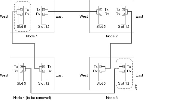
•![]() The node that is connected via its west port to the target (removal) node. For example, if you were removing Node 4 in Figure 16-3, Node 1 is the node connected via its west port to Node 4.
The node that is connected via its west port to the target (removal) node. For example, if you were removing Node 4 in Figure 16-3, Node 1 is the node connected via its west port to Node 4.
•![]() The node that is connected via its east port to the target (removal) node. In Figure 16-3, Node 3 is the node connected via its east port to Node 4.
The node that is connected via its east port to the target (removal) node. In Figure 16-3, Node 3 is the node connected via its east port to Node 4.
Figure 16-3 Four-Node, Two-Fiber BLSR Before a Node Is Removed
Step 6 ![]() Complete the "DLP-A298 Check the Network for Alarms and Conditions" task on page 15-3 to verify that the BLSR is free of alarms. If trouble is indicated (for example, a major alarm exists), resolve the problem before proceeding. See Chapter 9, "Manage Alarms" or, if necessary, refer to the Cisco ONS 15454 Troubleshooting Guide.
Complete the "DLP-A298 Check the Network for Alarms and Conditions" task on page 15-3 to verify that the BLSR is free of alarms. If trouble is indicated (for example, a major alarm exists), resolve the problem before proceeding. See Chapter 9, "Manage Alarms" or, if necessary, refer to the Cisco ONS 15454 Troubleshooting Guide.
Step 7 ![]() From the View menu, choose Go to Other Node. Choose the node that you will remove and click OK.
From the View menu, choose Go to Other Node. Choose the node that you will remove and click OK.
Step 8 ![]() Click the Circuits tab. If the Scope setting is set to Network, choose Node from the Scope pull-down menu. Make sure that the Filter button is off (not indented) to ensure that all circuits are visible.
Click the Circuits tab. If the Scope setting is set to Network, choose Node from the Scope pull-down menu. Make sure that the Filter button is off (not indented) to ensure that all circuits are visible.
Step 9 ![]() Delete all circuits that originate or terminate on the node. See the "DLP-A333 Delete Circuits and DWDM Optical Channel Network Connections" task on page 11-18.
Delete all circuits that originate or terminate on the node. See the "DLP-A333 Delete Circuits and DWDM Optical Channel Network Connections" task on page 11-18.
Step 10 ![]() Complete the "DLP-A304 Verify Pass-Through Circuits" task to verify that circuits passing through the target node enter and exit the node on the same STS and/or VT.
Complete the "DLP-A304 Verify Pass-Through Circuits" task to verify that circuits passing through the target node enter and exit the node on the same STS and/or VT.
Step 11 ![]() From the View menu, choose Go to Network View.
From the View menu, choose Go to Network View.
Step 12 ![]() Referring to the diagram created in Step 4, complete the "DLP-A303 Initiate a BLSR Force Ring Switch" task at each node that connects to the target (removal) node to force traffic away from it. You must perform a Force switch at each port connected to the target node. For example, in Figure 16-3, you would perform a Force switch on the east port of Node 3 and the west port of Node 1.
Referring to the diagram created in Step 4, complete the "DLP-A303 Initiate a BLSR Force Ring Switch" task at each node that connects to the target (removal) node to force traffic away from it. You must perform a Force switch at each port connected to the target node. For example, in Figure 16-3, you would perform a Force switch on the east port of Node 3 and the west port of Node 1.
Step 13 ![]() Click the Alarms tab.
Click the Alarms tab.
a. ![]() Verify that the alarm filter is not on. See the "DLP-A227 Disable Alarm Filtering" task on page 9-32 as necessary.
Verify that the alarm filter is not on. See the "DLP-A227 Disable Alarm Filtering" task on page 9-32 as necessary.
b. ![]() Verify that no unexplained alarms appear on the network. If alarms appear, investigate and resolve them before continuing. Refer to the Cisco ONS 15454 Troubleshooting Guide for procedures.
Verify that no unexplained alarms appear on the network. If alarms appear, investigate and resolve them before continuing. Refer to the Cisco ONS 15454 Troubleshooting Guide for procedures.
Step 14 ![]() Remove the fiber connections between the node being removed and the two neighboring nodes.
Remove the fiber connections between the node being removed and the two neighboring nodes.
Step 15 ![]() If the two nodes that will be connected after the BLSR node is removed have OC-48 AS trunk (span) cards and their K3 bytes were remapped, complete the "DLP-A422 Verify BLSR Extension Byte Mapping" task. If not, continue with Step 16.
If the two nodes that will be connected after the BLSR node is removed have OC-48 AS trunk (span) cards and their K3 bytes were remapped, complete the "DLP-A422 Verify BLSR Extension Byte Mapping" task. If not, continue with Step 16.
Step 16 ![]() Reconnect the fiber of the two neighboring nodes directly, west port to east port. For example, in Figure 16-3, the east port of Node 3 (Slot 12) connects to the west port of Node 1 (Slot 5).
Reconnect the fiber of the two neighboring nodes directly, west port to east port. For example, in Figure 16-3, the east port of Node 3 (Slot 12) connects to the west port of Node 1 (Slot 5).
Step 17 ![]() If you do not plan to add the removed node to a BLSR in the future, complete the "DLP-A196 Delete a BLSR from a Single Node" task. If you will add the node to a BLSR in the future, go to Step 18.
If you do not plan to add the removed node to a BLSR in the future, complete the "DLP-A196 Delete a BLSR from a Single Node" task. If you will add the node to a BLSR in the future, go to Step 18.
Step 18 ![]() If you delete a node that was in a login node group, you will see incomplete circuits for that node in the CTC network view. (Although it is no longer part of the ring, the removed node still reports to CTC until it is no longer in a login node group.) Delete the node from the login node group:
If you delete a node that was in a login node group, you will see incomplete circuits for that node in the CTC network view. (Although it is no longer part of the ring, the removed node still reports to CTC until it is no longer in a login node group.) Delete the node from the login node group:
a. ![]() From the CTC Edit menu, choose Preferences.
From the CTC Edit menu, choose Preferences.
b. ![]() In the Preferences dialog box, click the Login Node Groups tab.
In the Preferences dialog box, click the Login Node Groups tab.
c. ![]() Click the login node group tab containing the node you want to remove.
Click the login node group tab containing the node you want to remove.
d. ![]() Click the node you want to remove, then click Remove.
Click the node you want to remove, then click Remove.
e. ![]() Click OK.
Click OK.
Step 19 ![]() Click the History tab. Verify that the BLSR_RESYNC condition appears for every node in the BLSR.
Click the History tab. Verify that the BLSR_RESYNC condition appears for every node in the BLSR.
Step 20 ![]() Complete the "DLP-A194 Clear a BLSR Force Ring Switch" task to remove the Force protection switches.
Complete the "DLP-A194 Clear a BLSR Force Ring Switch" task to remove the Force protection switches.
Step 21 ![]() According to local site practice, complete the "NTP-A175 Two-Fiber BLSR Acceptance Test" procedure on page 6-22.
According to local site practice, complete the "NTP-A175 Two-Fiber BLSR Acceptance Test" procedure on page 6-22.
Stop. You have completed this procedure.
DLP-A195 Verify Timing in a Reduced Ring
Step 1 ![]() In node view, click the Provisioning > Timing tabs.
In node view, click the Provisioning > Timing tabs.
Step 2 ![]() Observe the Timing Mode field to see the type of timing (Line, External, Mixed) that has been set for that node.
Observe the Timing Mode field to see the type of timing (Line, External, Mixed) that has been set for that node.
Step 3 ![]() Scroll down to the Reference Lists and observe the NE Reference fields to see the timing references provisioned for that node.
Scroll down to the Reference Lists and observe the NE Reference fields to see the timing references provisioned for that node.
Step 4 ![]() If the removed node was the only BITS timing source, perform the following:
If the removed node was the only BITS timing source, perform the following:
a. ![]() Contact your synchronization coordinator or appropriate personnel before continuing with this procedure.
Contact your synchronization coordinator or appropriate personnel before continuing with this procedure.
b. ![]() Look for another node on the ring that can be used as a BITS source and set that node's Timing Mode to External. Choose that node as the primary timing source for all other nodes in the ring. See the "DLP-A157 Change the Node Timing Source" task on page 12-23.
Look for another node on the ring that can be used as a BITS source and set that node's Timing Mode to External. Choose that node as the primary timing source for all other nodes in the ring. See the "DLP-A157 Change the Node Timing Source" task on page 12-23.
c. ![]() If no node in the reduced ring can be used as a BITS source, choose one node to be your internal timing source. Set that node's Timing Mode to External, set BITS-1 and BITS-2 BITS In State to OOS, and set the NE Reference to Internal. Then, choose line timing for all other nodes in the ring. This forces the first node to be their primary timing source. (See the "DLP-A157 Change the Node Timing Source" task on page 12-23.)
If no node in the reduced ring can be used as a BITS source, choose one node to be your internal timing source. Set that node's Timing Mode to External, set BITS-1 and BITS-2 BITS In State to OOS, and set the NE Reference to Internal. Then, choose line timing for all other nodes in the ring. This forces the first node to be their primary timing source. (See the "DLP-A157 Change the Node Timing Source" task on page 12-23.)
Note ![]() This type of timing conforms to Stratum 3 requirements and is not considered optimal.
This type of timing conforms to Stratum 3 requirements and is not considered optimal.
Step 5 ![]() If the removed node was not the only BITS timing source, provision the adjacent nodes to line timing using SONET links (east and west) as timing sources, traceable to the node with external BITS timing. See the "NTP-A28 Set Up Timing" procedure on page 4-22.
If the removed node was not the only BITS timing source, provision the adjacent nodes to line timing using SONET links (east and west) as timing sources, traceable to the node with external BITS timing. See the "NTP-A28 Set Up Timing" procedure on page 4-22.
Step 6 ![]() Return to your originating procedure (NTP).
Return to your originating procedure (NTP).
DLP-A304 Verify Pass-Through Circuits
Step 1 ![]() In the CTC Circuits window, choose a circuit that passes through the BLSR or path protection node that will be removed and click Edit.
In the CTC Circuits window, choose a circuit that passes through the BLSR or path protection node that will be removed and click Edit.
Step 2 ![]() In the Edit Circuits window, check Show Detailed Map.
In the Edit Circuits window, check Show Detailed Map.
Step 3 ![]() Verify that the STS and VT mapping on the node's east and west ports are the same. For example, if the circuit mapping on the west port is s5/p1/S1 (Slot 5, Port 1, STS 1), verify that the mapping is STS 1 on the east port. If the circuit displays different STSs and/or VTs on the east and west ports, write down the name of the circuit. Figure 16-4 shows a circuit passing through a node (doc-124) on the same STS (STS 2).
Verify that the STS and VT mapping on the node's east and west ports are the same. For example, if the circuit mapping on the west port is s5/p1/S1 (Slot 5, Port 1, STS 1), verify that the mapping is STS 1 on the east port. If the circuit displays different STSs and/or VTs on the east and west ports, write down the name of the circuit. Figure 16-4 shows a circuit passing through a node (doc-124) on the same STS (STS 2).
Figure 16-4 Verifying Pass-Through STSs

Step 4 ![]() Repeat Steps 1 to 3 for each circuit in the Circuits tab.
Repeat Steps 1 to 3 for each circuit in the Circuits tab.
Step 5 ![]() Delete and recreate each circuit recorded in Step 3 that entered/exited the node on different STSs. To delete the circuit, see the "DLP-A333 Delete Circuits and DWDM Optical Channel Network Connections" task on page 11-18. To create the circuit, see Chapter 8, "Create Circuits and VT Tunnels."
Delete and recreate each circuit recorded in Step 3 that entered/exited the node on different STSs. To delete the circuit, see the "DLP-A333 Delete Circuits and DWDM Optical Channel Network Connections" task on page 11-18. To create the circuit, see Chapter 8, "Create Circuits and VT Tunnels."
Step 6 ![]() Return to your originating procedure (NTP).
Return to your originating procedure (NTP).
DLP-A422 Verify BLSR Extension Byte Mapping
Step 1 ![]() In network view, double-click a BLSR node with OC-48 AS trunk (span) cards that will be reconnected after a BLSR node removal.
In network view, double-click a BLSR node with OC-48 AS trunk (span) cards that will be reconnected after a BLSR node removal.
Step 2 ![]() Double-click one OC-48 AS BLSR trunk card.
Double-click one OC-48 AS BLSR trunk card.
Step 3 ![]() Click the Provisioning > Line tabs.
Click the Provisioning > Line tabs.
Step 4 ![]() Record on paper the byte in the BLSR Ext Byte column.
Record on paper the byte in the BLSR Ext Byte column.
Step 5 ![]() Repeat Steps 2 through 4 for the second OC-48 AS trunk card.
Repeat Steps 2 through 4 for the second OC-48 AS trunk card.
Step 6 ![]() If the node at the other end of the new span contains OC-48 AS trunk cards, repeat Steps 1 through 5 at the node. If it does not have OC-48 AS cards, their trunk cards are mapped to the K3 extension byte. Continue with Step 7.
If the node at the other end of the new span contains OC-48 AS trunk cards, repeat Steps 1 through 5 at the node. If it does not have OC-48 AS cards, their trunk cards are mapped to the K3 extension byte. Continue with Step 7.
Step 7 ![]() If the trunk cards on each end of the new span are mapped to the same BLSR extension byte, continue with Step 8. If they are not the same, remap the extension byte of the trunk cards at one of the nodes. See the "DLP-A89 Remap the K3 Byte" task on page 6-18.
If the trunk cards on each end of the new span are mapped to the same BLSR extension byte, continue with Step 8. If they are not the same, remap the extension byte of the trunk cards at one of the nodes. See the "DLP-A89 Remap the K3 Byte" task on page 6-18.
Step 8 ![]() Return to your originating procedure (NTP).
Return to your originating procedure (NTP).
DLP-A196 Delete a BLSR from a Single Node
Step 1 ![]() In node view, display the node that was removed from the BLSR:
In node view, display the node that was removed from the BLSR:
•![]() If the node that was removed is connected to the same LAN as your computer, from the File menu, choose Add Node, then enter the node name or IP address.
If the node that was removed is connected to the same LAN as your computer, from the File menu, choose Add Node, then enter the node name or IP address.
•![]() If the node that was removed is not connected to the same LAN as your computer, you must connect to the node using a direct connection. See Chapter 3, "Connect the PC and Log into the GUI" for procedures.
If the node that was removed is not connected to the same LAN as your computer, you must connect to the node using a direct connection. See Chapter 3, "Connect the PC and Log into the GUI" for procedures.
Step 2 ![]() Click the Provisioning > BLSR tabs.
Click the Provisioning > BLSR tabs.
Step 3 ![]() Highlight the ring and click Delete.
Highlight the ring and click Delete.
Step 4 ![]() In the Suggestion dialog box, click OK.
In the Suggestion dialog box, click OK.
Step 5 ![]() In the confirmation message, confirm that this is the ring you want to delete. If so, click Yes.
In the confirmation message, confirm that this is the ring you want to delete. If so, click Yes.
Step 6 ![]() Return to your originating procedure (NTP).
Return to your originating procedure (NTP).
NTP-A105 Add a Path Protection Node
Purpose |
This procedure adds a node to a Path Protection. |
Tools/Equipment |
None |
Prerequisite Procedures |
Cards must be installed and node turn-up procedures completed on the node that will be added to the Path Protection. See Chapter 2, "Install Cards and Fiber-Optic Cable," and Chapter 4, "Turn Up Node." |
Required/As Needed |
As needed |
Onsite/Remote |
Onsite |
Security Level |
Provisioning or higher |
Step 1 ![]() According to local site practice, complete the "NTP-A108 Back Up the Database" procedure on page 17-7 for all the nodes in the ring.
According to local site practice, complete the "NTP-A108 Back Up the Database" procedure on page 17-7 for all the nodes in the ring.
Step 2 ![]() Log into an existing node in the path protection where you want to add a node. See the "DLP-A60 Log into CTC" task on page 3-24 for instructions. In order to have CTC visibility to the new node after it is added, you must be an authorized user on the node and you must have IP connectivity to the node.
Log into an existing node in the path protection where you want to add a node. See the "DLP-A60 Log into CTC" task on page 3-24 for instructions. In order to have CTC visibility to the new node after it is added, you must be an authorized user on the node and you must have IP connectivity to the node.
Step 3 ![]() Complete the "DLP-A298 Check the Network for Alarms and Conditions" task on page 15-3 to verify that the path protection is free of major alarms or problems. If trouble is indicated (for example, a major alarm exists), resolve the problem before proceeding. See the Cisco ONS 15454 Troubleshooting Guide, as necessary.
Complete the "DLP-A298 Check the Network for Alarms and Conditions" task on page 15-3 to verify that the path protection is free of major alarms or problems. If trouble is indicated (for example, a major alarm exists), resolve the problem before proceeding. See the Cisco ONS 15454 Troubleshooting Guide, as necessary.
Step 4 ![]() Verify the card installation on the new node. See the "NTP-A24 Verify Card Installation" procedure on page 4-2. Check that the OC-N cards that will serve as the path protection trunk (span) cards match the path protection optical rate of the trunk cards to which the new node will be connected. For example, if the adjacent nodes have OC-48 trunk cards, the new node must have OC-48 cards installed. If the OC-N cards are not installed or the rate does not match the rate of the adjacent node trunk cards, complete the "NTP-A16 Install the OC-N Cards" procedure on page 2-12 to install them.
Verify the card installation on the new node. See the "NTP-A24 Verify Card Installation" procedure on page 4-2. Check that the OC-N cards that will serve as the path protection trunk (span) cards match the path protection optical rate of the trunk cards to which the new node will be connected. For example, if the adjacent nodes have OC-48 trunk cards, the new node must have OC-48 cards installed. If the OC-N cards are not installed or the rate does not match the rate of the adjacent node trunk cards, complete the "NTP-A16 Install the OC-N Cards" procedure on page 2-12 to install them.
Step 5 ![]() Verify that fiber is available to connect the new node to the existing nodes.
Verify that fiber is available to connect the new node to the existing nodes.
Step 6 ![]() Complete the "NTP-A35 Verify Node Turn Up" procedure on page 6-2.
Complete the "NTP-A35 Verify Node Turn Up" procedure on page 6-2.
Step 7 ![]() Determine if the following conditions are present.
Determine if the following conditions are present.
•![]() The IP address for the new node is on the same subnet as other nodes in the network.
The IP address for the new node is on the same subnet as other nodes in the network.
•![]() On the new node Provisioning > Network > General subtab, Craft Access Only is not checked under Gateway Settings.
On the new node Provisioning > Network > General subtab, Craft Access Only is not checked under Gateway Settings.
•![]() A CTC computer is directly connected to the new node.
A CTC computer is directly connected to the new node.
•![]() CTC computers are directly connected to other nodes on the same subnet.
CTC computers are directly connected to other nodes on the same subnet.
If the conditions are not present, continue with Step 8. If conditions are present, complete the "DLP-A65 Create a Static Route" task on page 4-15 on the node that will be added to the path protection. Use the following settings:
•![]() Destination IP address: IP address of the CTC computer connected to the new node
Destination IP address: IP address of the CTC computer connected to the new node
•![]() Net Mask: 255.255.255.255
Net Mask: 255.255.255.255
•![]() Next Hop: IP address of the Cisco ONS 15454
Next Hop: IP address of the Cisco ONS 15454
•![]() Cost: 1
Cost: 1
To view Gateway Settings, see the "DLP-A249 Provision IP Settings" task on page 4-10.
Step 8 ![]() Log into the new node:
Log into the new node:
•![]() If the node has a LAN connection and appears on the network map, from the View menu, choose Go to Other Node, then enter the new node.
If the node has a LAN connection and appears on the network map, from the View menu, choose Go to Other Node, then enter the new node.
•![]() If the new node is not connected to the network, log into it using the "DLP-A60 Log into CTC" task on page 3-24.
If the new node is not connected to the network, log into it using the "DLP-A60 Log into CTC" task on page 3-24.
Step 9 ![]() Click the Alarms tab. Verify that no critical or major alarms are present, nor any facility alarms, such as LOS, LOF, AIS-L, SF, and SD. If trouble is indicated (for example, a major alarm exists), resolve the problem before proceeding. See the Cisco ONS 15454 Troubleshooting Guide, as necessary.
Click the Alarms tab. Verify that no critical or major alarms are present, nor any facility alarms, such as LOS, LOF, AIS-L, SF, and SD. If trouble is indicated (for example, a major alarm exists), resolve the problem before proceeding. See the Cisco ONS 15454 Troubleshooting Guide, as necessary.
Step 10 ![]() (Optional) Create test circuits, making sure they pass through the path protection trunk cards, and run test traffic through the node to ensure that the cards are functioning properly. See the "NTP-A189 Create a Manually Routed OC-N Circuit" procedure on page 8-47 and the "NTP-A62 Test OC-N Circuits" procedure on page 8-54 for information.
(Optional) Create test circuits, making sure they pass through the path protection trunk cards, and run test traffic through the node to ensure that the cards are functioning properly. See the "NTP-A189 Create a Manually Routed OC-N Circuit" procedure on page 8-47 and the "NTP-A62 Test OC-N Circuits" procedure on page 8-54 for information.
Step 11 ![]() Create the DCC terminations on the new node. See the "DLP-A354 Provision SONET DCC Terminations" task on page 6-4.
Create the DCC terminations on the new node. See the "DLP-A354 Provision SONET DCC Terminations" task on page 6-4.
Step 12 ![]() From the View menu, choose Go to Network View.
From the View menu, choose Go to Network View.
Step 13 ![]() Complete the "DLP-A197 Initiate a Path Protection Force Switch" task to switch traffic away from the span that will be broken to connect to the new node.
Complete the "DLP-A197 Initiate a Path Protection Force Switch" task to switch traffic away from the span that will be broken to connect to the new node.
Step 14 ![]() Two nodes will connect directly to the new node; remove their fiber connections:
Two nodes will connect directly to the new node; remove their fiber connections:
a. ![]() Remove the east fiber connection from the node that will connect to the west port of the new node.
Remove the east fiber connection from the node that will connect to the west port of the new node.
b. ![]() Remove the west fiber connection from the node that will connect to the east port of the new node.
Remove the west fiber connection from the node that will connect to the east port of the new node.
Step 15 ![]() Replace the removed fibers with the fibers that are connected to the new node.
Replace the removed fibers with the fibers that are connected to the new node.
Step 16 ![]() Log out of CTC and log back into a node in the network.
Log out of CTC and log back into a node in the network.
Step 17 ![]() From the View menu, choose Go to Network View to display the path protection nodes. The new node should appear in the network map. Wait for a few minutes to allow all the nodes to appear.
From the View menu, choose Go to Network View to display the path protection nodes. The new node should appear in the network map. Wait for a few minutes to allow all the nodes to appear.
Step 18 ![]() Click the Circuits tab and wait for all the circuits to appear, including spans. Count the number of incomplete circuits.
Click the Circuits tab and wait for all the circuits to appear, including spans. Count the number of incomplete circuits.
Note ![]() UNEQ-P alarms may appear on the nodes in your network, this is normal, and the alarms will clear after the circuits are updated.
UNEQ-P alarms may appear on the nodes in your network, this is normal, and the alarms will clear after the circuits are updated.
Step 19 ![]() In the network view, right-click the new node and choose Update Circuits With New Node from the shortcut menu. Wait for the confirmation dialog box to appear. Verify that the number of updated circuits in the dialog box is correct.
In the network view, right-click the new node and choose Update Circuits With New Node from the shortcut menu. Wait for the confirmation dialog box to appear. Verify that the number of updated circuits in the dialog box is correct.
Step 20 ![]() Click the Circuits tab and verify that no incomplete circuits are present.
Click the Circuits tab and verify that no incomplete circuits are present.
Note ![]() If the circuits take more than a minute to appear, log out of CTC, then log back in.
If the circuits take more than a minute to appear, log out of CTC, then log back in.
Step 21 ![]() Complete the "DLP-A198 Clear a Path Protection Force Switch" task to clear the protection switch.
Complete the "DLP-A198 Clear a Path Protection Force Switch" task to clear the protection switch.
Step 22 ![]() According to local site practice, complete the "NTP-A177 Path Protection Acceptance Test" procedure on page 6-38.
According to local site practice, complete the "NTP-A177 Path Protection Acceptance Test" procedure on page 6-38.
Stop. You have completed this procedure.
DLP-A197 Initiate a Path Protection Force Switch
Step 1 ![]() From the View menu, choose Go to Network View.
From the View menu, choose Go to Network View.
Step 2 ![]() Right-click the span where you want to switch path protection traffic away. Choose Circuits from the shortcut menu.
Right-click the span where you want to switch path protection traffic away. Choose Circuits from the shortcut menu.
Step 3 ![]() In the Circuits on Span dialog box, choose FORCE SWITCH AWAY. Click Apply.
In the Circuits on Span dialog box, choose FORCE SWITCH AWAY. Click Apply.
Step 4 ![]() In the Confirm UPSR Switch dialog box, click Yes.
In the Confirm UPSR Switch dialog box, click Yes.
Step 5 ![]() In the Protection Switch Result dialog box, click OK.
In the Protection Switch Result dialog box, click OK.
In the Circuits on Span window, the Switch State for all circuits is FORCE. Figure 16-5 shows an example.
Figure 16-5 Circuits on Span Dialog Box with a Force Switch
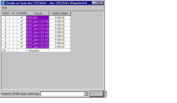
Note ![]() A Force switch request on a span or card causes CTC to raise a FORCED-REQ condition. The condition clears when you clear the Force switch.
A Force switch request on a span or card causes CTC to raise a FORCED-REQ condition. The condition clears when you clear the Force switch.
Step 6 ![]() Return to your originating procedure (NTP).
Return to your originating procedure (NTP).
DLP-A198 Clear a Path Protection Force Switch
Purpose |
This task clears a path protection Force switch. |
Tools/Equipment |
None |
Prerequisite Procedures |
|
Required/As Needed |
As needed |
Onsite/Remote |
Onsite or remote |
Security Level |
Provisioning or higher |
Step 1 ![]() From the View menu at the node view, choose Go to Network View.
From the View menu at the node view, choose Go to Network View.
Step 2 ![]() Right-click the span where you want to clear the switch. Choose Circuits from the shortcut menu.
Right-click the span where you want to clear the switch. Choose Circuits from the shortcut menu.
Step 3 ![]() In the Circuits on Span dialog box, choose CLEAR to remove the Force switch. Click Apply.
In the Circuits on Span dialog box, choose CLEAR to remove the Force switch. Click Apply.
Step 4 ![]() In the Confirm UPSR Switch dialog box, click Yes.
In the Confirm UPSR Switch dialog box, click Yes.
Step 5 ![]() In the Protection Switch Result dialog box, click OK.
In the Protection Switch Result dialog box, click OK.
In the Circuits on Span window, the Switch State for all path protection circuits is CLEAR.
Step 6 ![]() Return to your originating procedure (NTP).
Return to your originating procedure (NTP).
NTP-A106 Remove a Path Protection Node
Purpose |
This procedure removes a node from a path protection. |
Tools/Equipment |
None |
Prerequisite Procedures |
|
Required/As Needed |
As needed |
Onsite/Remote |
Onsite |
Security Level |
Provisioning or higher |
Step 1 ![]() Draw a diagram of the path protection where you will remove the node. In the diagram, identify the following:
Draw a diagram of the path protection where you will remove the node. In the diagram, identify the following:
•![]() The node that is connected through its west port to the node that will be removed.
The node that is connected through its west port to the node that will be removed.
•![]() The node that is connected through its east port to the node that will be removed.
The node that is connected through its east port to the node that will be removed.
Step 2 ![]() Log into a node in the network where you want to remove a path protection node. See the "DLP-A60 Log into CTC" task on page 3-24 for instructions.
Log into a node in the network where you want to remove a path protection node. See the "DLP-A60 Log into CTC" task on page 3-24 for instructions.
Step 3 ![]() Complete the "DLP-A298 Check the Network for Alarms and Conditions" task on page 15-3 to verify that the path protection is free of alarms. If trouble is indicated (for example, a major alarm exists), resolve the problem before proceeding. See Chapter 9, "Manage Alarms" or, if necessary, refer to the Cisco ONS 15454 Troubleshooting Guide.
Complete the "DLP-A298 Check the Network for Alarms and Conditions" task on page 15-3 to verify that the path protection is free of alarms. If trouble is indicated (for example, a major alarm exists), resolve the problem before proceeding. See Chapter 9, "Manage Alarms" or, if necessary, refer to the Cisco ONS 15454 Troubleshooting Guide.
Step 4 ![]() Complete the "DLP-A333 Delete Circuits and DWDM Optical Channel Network Connections" procedure on page 11-18 for circuits that originate or terminate in the node you will remove. (If a circuit has multiple drops, delete only the drops that terminate on the node you are deleting.
Complete the "DLP-A333 Delete Circuits and DWDM Optical Channel Network Connections" procedure on page 11-18 for circuits that originate or terminate in the node you will remove. (If a circuit has multiple drops, delete only the drops that terminate on the node you are deleting.
Step 5 ![]() Complete the "DLP-A304 Verify Pass-Through Circuits" task to verify that circuits passing through the target node enter and exit the node on the same STS and/or VT.
Complete the "DLP-A304 Verify Pass-Through Circuits" task to verify that circuits passing through the target node enter and exit the node on the same STS and/or VT.
Step 6 ![]() Complete the "DLP-A197 Initiate a Path Protection Force Switch" task for all spans connected to the node you are removing.
Complete the "DLP-A197 Initiate a Path Protection Force Switch" task for all spans connected to the node you are removing.
Step 7 ![]() Remove all fiber connections between the node being removed and the two neighboring nodes.
Remove all fiber connections between the node being removed and the two neighboring nodes.
Step 8 ![]() Reconnect the fiber of the two neighboring nodes directly, west port to east port.
Reconnect the fiber of the two neighboring nodes directly, west port to east port.
Note ![]() If you delete a node that was in a login node group, you will see incomplete circuits for that node in CTC network view. (Although it is no longer part of the ring, the removed node still reports to CTC until it is no longer in a login node group.)
If you delete a node that was in a login node group, you will see incomplete circuits for that node in CTC network view. (Although it is no longer part of the ring, the removed node still reports to CTC until it is no longer in a login node group.)
Step 9 ![]() Exit CTC and log back in. See the "DLP-A60 Log into CTC" task on page 3-24 for instructions.
Exit CTC and log back in. See the "DLP-A60 Log into CTC" task on page 3-24 for instructions.
Step 10 ![]() Log into each newly connected node and click the Alarms tab. Verify that the span cards are free of alarms. Resolve any alarms before proceeding. Refer to the Cisco ONS 15454 Troubleshooting Guide.
Log into each newly connected node and click the Alarms tab. Verify that the span cards are free of alarms. Resolve any alarms before proceeding. Refer to the Cisco ONS 15454 Troubleshooting Guide.
Step 11 ![]() Complete the "DLP-A195 Verify Timing in a Reduced Ring" task.
Complete the "DLP-A195 Verify Timing in a Reduced Ring" task.
Step 12 ![]() Complete the "DLP-A198 Clear a Path Protection Force Switch" task to clear the protection switch.
Complete the "DLP-A198 Clear a Path Protection Force Switch" task to clear the protection switch.
Step 13 ![]() Click the Circuits tab and verify that no incomplete circuits are present.
Click the Circuits tab and verify that no incomplete circuits are present.
Step 14 ![]() Complete the "NTP-A177 Path Protection Acceptance Test" procedure on page 6-38.
Complete the "NTP-A177 Path Protection Acceptance Test" procedure on page 6-38.
Stop. You have completed this procedure.
NTP-A262 Add a Node to a Linear ADM
Note ![]() Optical transmit and receive levels should be in their acceptable range as shown in the specifications section for each card in Table 2-5 on page 2-31.
Optical transmit and receive levels should be in their acceptable range as shown in the specifications section for each card in Table 2-5 on page 2-31.
Note ![]() In a linear ADM configuration, two OC-N cards in 1+1 protection are connected to two OC-N cards in 1+1 protection on a second node. On the second node, two more OC-N cards are connected to a third node. The third node can be connected to a fourth node, and so on, depending on the number of nodes in the linear ADM. Slots 1 to 4 and 14 to 17 or Slots 5 to 6 and 12 to 13 can be used if connections between nodes are consistent. For example, Slot 5 on the first linear ADM node connects to Slot 5 on the second linear ADM node for the working path, and Slot 6 connects to Slot 6 for the protect path. The working OC-N ports have DCC terminations, and the OC-N cards are in a 1+1 protection group.
In a linear ADM configuration, two OC-N cards in 1+1 protection are connected to two OC-N cards in 1+1 protection on a second node. On the second node, two more OC-N cards are connected to a third node. The third node can be connected to a fourth node, and so on, depending on the number of nodes in the linear ADM. Slots 1 to 4 and 14 to 17 or Slots 5 to 6 and 12 to 13 can be used if connections between nodes are consistent. For example, Slot 5 on the first linear ADM node connects to Slot 5 on the second linear ADM node for the working path, and Slot 6 connects to Slot 6 for the protect path. The working OC-N ports have DCC terminations, and the OC-N cards are in a 1+1 protection group.
Step 1 ![]() According to local site practice, complete the "NTP-A108 Back Up the Database" procedure on page 17-7 for all the nodes in the ring.
According to local site practice, complete the "NTP-A108 Back Up the Database" procedure on page 17-7 for all the nodes in the ring.
Step 2 ![]() At the new node, complete one of the following procedures:
At the new node, complete one of the following procedures:
•![]() If the node has not been turned up, complete all procedures in Chapter 4, "Turn Up Node."
If the node has not been turned up, complete all procedures in Chapter 4, "Turn Up Node."
•![]() If the node has been turned up, complete the "NTP-A35 Verify Node Turn Up" procedure on page 6-2.
If the node has been turned up, complete the "NTP-A35 Verify Node Turn Up" procedure on page 6-2.
Step 3 ![]() Verify that the new node has two OC-N cards with the same rate as the linear ADM. If the OC-N cards are not installed, complete the "NTP-A16 Install the OC-N Cards" procedure on page 2-12.
Verify that the new node has two OC-N cards with the same rate as the linear ADM. If the OC-N cards are not installed, complete the "NTP-A16 Install the OC-N Cards" procedure on page 2-12.
Step 4 ![]() Complete "DLP-A73 Create a 1+1 Protection Group" task on page 4-30 for the two OC-N cards that will connect to the linear ADM node.
Complete "DLP-A73 Create a 1+1 Protection Group" task on page 4-30 for the two OC-N cards that will connect to the linear ADM node.
Step 5 ![]() Complete the "DLP-A354 Provision SONET DCC Terminations" task on page 6-4 for the working OC-N card at the new node. Make sure to set the Port State in the Create SDCC Termination dialog box to IS. (Do not create a DCC termination on the protect card.)
Complete the "DLP-A354 Provision SONET DCC Terminations" task on page 6-4 for the working OC-N card at the new node. Make sure to set the Port State in the Create SDCC Termination dialog box to IS. (Do not create a DCC termination on the protect card.)
Note ![]() DCC failure alarms appear until you create DCC terminations in the linear ADM node and connect the fiber during Step 12.
DCC failure alarms appear until you create DCC terminations in the linear ADM node and connect the fiber during Step 12.
Step 6 ![]() Complete the "DLP-A60 Log into CTC" task on page 3-24 at the linear ADM node that will connect to the new node. If you are already logged in, continue with Step 7.
Complete the "DLP-A60 Log into CTC" task on page 3-24 at the linear ADM node that will connect to the new node. If you are already logged in, continue with Step 7.
Step 7 ![]() Complete the "DLP-A298 Check the Network for Alarms and Conditions" task on page 15-3.
Complete the "DLP-A298 Check the Network for Alarms and Conditions" task on page 15-3.
Step 8 ![]() Install the OC-N cards that will connect to the new node. See "NTP-A16 Install the OC-N Cards" procedure on page 2-12. If the cards are already installed, continue with Step 9.
Install the OC-N cards that will connect to the new node. See "NTP-A16 Install the OC-N Cards" procedure on page 2-12. If the cards are already installed, continue with Step 9.
Step 9 ![]() Connect the working card at the existing linear ADM node to the working card at the new node. See "DLP-A428 Install Fiber-Optic Cables in a 1+1 Configuration" procedure on page 2-33.
Connect the working card at the existing linear ADM node to the working card at the new node. See "DLP-A428 Install Fiber-Optic Cables in a 1+1 Configuration" procedure on page 2-33.
Step 10 ![]() Connect the protect card at the existing linear ADM node to the protect card at the new node.
Connect the protect card at the existing linear ADM node to the protect card at the new node.
Step 11 ![]() Complete "DLP-A73 Create a 1+1 Protection Group" task on page 4-30 for the two OC-N cards that connect to the new node.
Complete "DLP-A73 Create a 1+1 Protection Group" task on page 4-30 for the two OC-N cards that connect to the new node.
Step 12 ![]() Complete the "DLP-A354 Provision SONET DCC Terminations" task on page 6-4 for the working OC-N card that connects to the working card on the new node. Make sure to set the Port State in the Create SDCC Termination dialog box to IS. (Do not create a DCC termination for the protect card.)
Complete the "DLP-A354 Provision SONET DCC Terminations" task on page 6-4 for the working OC-N card that connects to the working card on the new node. Make sure to set the Port State in the Create SDCC Termination dialog box to IS. (Do not create a DCC termination for the protect card.)
Step 13 ![]() From the View menu, choose Go to Network View. Verify that the newly created linear ADM configuration is correct. Two green span lines should appear between each linear node.
From the View menu, choose Go to Network View. Verify that the newly created linear ADM configuration is correct. Two green span lines should appear between each linear node.
Step 14 ![]() Complete the "DLP-A298 Check the Network for Alarms and Conditions" task on page 15-3 to verify that no unexpected alarms or conditions are present.
Complete the "DLP-A298 Check the Network for Alarms and Conditions" task on page 15-3 to verify that no unexpected alarms or conditions are present.
Stop. You have completed this procedure.
NTP-A263 Remove a Node from a Linear ADM
Step 1 ![]() According to local site practice, complete the "NTP-A108 Back Up the Database" procedure on page 17-7 for all the nodes in the ring.
According to local site practice, complete the "NTP-A108 Back Up the Database" procedure on page 17-7 for all the nodes in the ring.
Step 2 ![]() Complete the "DLP-A60 Log into CTC" task on page 3-24 at the linear ADM node that will be removed. If you are already logged in, continue with Step 3.
Complete the "DLP-A60 Log into CTC" task on page 3-24 at the linear ADM node that will be removed. If you are already logged in, continue with Step 3.
Step 3 ![]() Complete the "DLP-A298 Check the Network for Alarms and Conditions" task on page 15-3.
Complete the "DLP-A298 Check the Network for Alarms and Conditions" task on page 15-3.
Step 4 ![]() Click the Circuits tab. If the Scope field (lower-right corner) is not set to Node, change it to Node.
Click the Circuits tab. If the Scope field (lower-right corner) is not set to Node, change it to Node.
Step 5 ![]() If circuits originate or terminate on the node, complete the "DLP-A333 Delete Circuits and DWDM Optical Channel Network Connections" procedure on page 11-18 to remove them.
If circuits originate or terminate on the node, complete the "DLP-A333 Delete Circuits and DWDM Optical Channel Network Connections" procedure on page 11-18 to remove them.
Step 6 ![]() Remove the DCC termination on the working OC-N linear ADM card. See "NTP-A255 Delete Communications Channel Terminations" task on page 12-20.
Remove the DCC termination on the working OC-N linear ADM card. See "NTP-A255 Delete Communications Channel Terminations" task on page 12-20.
Step 7 ![]() Navigate to the node connected to the node that will be removed.
Navigate to the node connected to the node that will be removed.
Step 8 ![]() Remove the DCC termination on the working OC-N linear ADM card that is connected to the node that will be removed. See the "NTP-A255 Delete Communications Channel Terminations" task on page 12-20.
Remove the DCC termination on the working OC-N linear ADM card that is connected to the node that will be removed. See the "NTP-A255 Delete Communications Channel Terminations" task on page 12-20.
Step 9 ![]() Remove the fiber from the OC-N cards connected to the node that will be removed.
Remove the fiber from the OC-N cards connected to the node that will be removed.
Step 10 ![]() Display the network view to verify that the linear ADM configuration is correct. Two green span lines should appear between each linear node.
Display the network view to verify that the linear ADM configuration is correct. Two green span lines should appear between each linear node.
Step 11 ![]() Complete the "DLP-A298 Check the Network for Alarms and Conditions" task on page 15-3 to verify that no unexpected alarms or conditions are present.
Complete the "DLP-A298 Check the Network for Alarms and Conditions" task on page 15-3 to verify that no unexpected alarms or conditions are present.
Stop. You have completed this procedure.
 Feedback