- About this Guide
- Chapter 1, Install Shelf and Backplane Hardware
- Chapter 2, Install Cards and Fiber-Optic Cable
- Chapter 3, Set Up PC and Log Into the GUI
- Chapter 4, Turn Up Node
- Chapter 5, Turn Up DWDM Node
- Chapter 6, Turn Up Network
- Chapter 7, Turn Up DWDM Network
- Chapter 8, Create Circuits and VT Tunnels
- Chapter 9, Manage Alarms
- Chapter 10, Monitor Performance
- Chapter 11, Manage Circuits
- Chapter 12, Change Node Settings
- Chapter 13, Change Card Settings
- Chapter 14, Upgrade Cards and Spans
- Chapter 15, Convert Network Configurations
- Chapter 16, Add and Remove Nodes
- Chapter 17, Maintain the Node
- Chapter 18, Power Down Node
- Appendix A, CTC Information and Shortcuts
- Appendix B, Specifications
- DLP-A530 Install the Tie-Down Bar
- DLP-A23 Install DS-1 Cables Using Electrical Interface Adapters (Balun)
- DLP-A24 Install DS-1 AMP Champ Cables on the AMP Champ EIA
- DLP-A25 Install Coaxial Cable With BNC Connectors
- DLP-A26 Install Coaxial Cable With High-Density BNC Connectors
- DLP-A27 Install Coaxial Cable with SMB Connectors
Install the Shelf and Backplane Cable
This chapter provides procedures for installing the Cisco ONS 15454. For a summary of the tools and equipment required for installation, see the "Required Tools and Equipment" section.
Before You Begin
This section lists the chapter procedures (NTPs). Turn to a procedure for applicable tasks (DLPs).
1. ![]() A1 Unpack and Inspect the ONS 15454 Shelf Assembly—Complete this procedure before continuing with the "A2 Install the Shelf Assembly" procedure.
A1 Unpack and Inspect the ONS 15454 Shelf Assembly—Complete this procedure before continuing with the "A2 Install the Shelf Assembly" procedure.
2. ![]() A2 Install the Shelf Assembly—Complete this procedure to install the shelf assembly in a rack.
A2 Install the Shelf Assembly—Complete this procedure to install the shelf assembly in a rack.
3. ![]() A3 Open and Remove the Front Door—Complete this procedure to access the equipment before continuing with other procedures.
A3 Open and Remove the Front Door—Complete this procedure to access the equipment before continuing with other procedures.
4. ![]() A4 Remove the Backplane Covers—Complete this procedure to access the backplane before continuing with other procedures.
A4 Remove the Backplane Covers—Complete this procedure to access the backplane before continuing with other procedures.
5. ![]() A5 Install the EIAs—Complete this procedure if you plan to install electrical cards. This procedure is a prerequisite to the "A9 Install the Electrical Card Cables on the Backplane" procedure.
A5 Install the EIAs—Complete this procedure if you plan to install electrical cards. This procedure is a prerequisite to the "A9 Install the Electrical Card Cables on the Backplane" procedure.
6. ![]() A6 Install the Power and Ground—Complete this procedure before continuing with the "A7 Install the Fan-Tray Assembly" procedure.
A6 Install the Power and Ground—Complete this procedure before continuing with the "A7 Install the Fan-Tray Assembly" procedure.
7. ![]() A7 Install the Fan-Tray Assembly—Complete this procedure to install the fan-tray assembly in the shelf.
A7 Install the Fan-Tray Assembly—Complete this procedure to install the fan-tray assembly in the shelf.
8. ![]() A119 Install the Alarm Expansion Panel—Complete this procedure if you are planning to install the Alarm Interface Controller-International (AIC-I) card and want to increase the number of alarm contacts provided by the AIC-I card.
A119 Install the Alarm Expansion Panel—Complete this procedure if you are planning to install the Alarm Interface Controller-International (AIC-I) card and want to increase the number of alarm contacts provided by the AIC-I card.
9. ![]() A8 Attach Wires to Alarm, Timing, LAN, and Craft Pin Connections—Complete this procedure as needed to set up wire-wrap pin connections.
A8 Attach Wires to Alarm, Timing, LAN, and Craft Pin Connections—Complete this procedure as needed to set up wire-wrap pin connections.
10. ![]() A120 Install an External Wire-Wrap Panel to the AEP—Complete this procedure to connect an external wire-wrap panel to the alarm expansion panel (AEP).
A120 Install an External Wire-Wrap Panel to the AEP—Complete this procedure to connect an external wire-wrap panel to the alarm expansion panel (AEP).
11. ![]() A9 Install the Electrical Card Cables on the Backplane—Complete this procedure if you plan to install electrical cards.
A9 Install the Electrical Card Cables on the Backplane—Complete this procedure if you plan to install electrical cards.
12. ![]() A10 Route Electrical Cables—Complete this procedure as needed before continuing with the "A11 Install the Rear Cover" procedure.
A10 Route Electrical Cables—Complete this procedure as needed before continuing with the "A11 Install the Rear Cover" procedure.
13. ![]() A11 Install the Rear Cover—Complete this procedure as needed to install the rear cover.
A11 Install the Rear Cover—Complete this procedure as needed to install the rear cover.
14. ![]() A12 Install Ferrites—Complete this procedure as needed to attach ferrites to power cables.
A12 Install Ferrites—Complete this procedure as needed to attach ferrites to power cables.
15. ![]() A238 Install Optional DWDM Equipment—Complete this procedure if you are installing the optional equipment associated with DWDM applications.
A238 Install Optional DWDM Equipment—Complete this procedure if you are installing the optional equipment associated with DWDM applications.
16. ![]() A13 Perform the Shelf Installation Acceptance Test—Complete this procedure to determine if you have correctly completed all other procedures in the chapter.
A13 Perform the Shelf Installation Acceptance Test—Complete this procedure to determine if you have correctly completed all other procedures in the chapter.

Warning ![]() Only trained and qualified personnel should be allowed to install, replace, or service this equipment.
Only trained and qualified personnel should be allowed to install, replace, or service this equipment.
Warning ![]() The ONS 15454 is intended for installation in restricted access areas. A restricted access area is where access can only be gained by service personnel through the use of a special tool, lock, key, or other means of security. A restricted access area is controlled by the authority responsible for the location.
The ONS 15454 is intended for installation in restricted access areas. A restricted access area is where access can only be gained by service personnel through the use of a special tool, lock, key, or other means of security. A restricted access area is controlled by the authority responsible for the location.
Warning ![]() The ONS 15454 is suitable for mounting on concrete or other noncombustible surfaces only.
The ONS 15454 is suitable for mounting on concrete or other noncombustible surfaces only.
Warning ![]() The covers are an integral part of the safety design of the product. Do not operate the unit without the covers installed.
The covers are an integral part of the safety design of the product. Do not operate the unit without the covers installed.
Required Tools and Equipment
You need the following tools and equipment to install and test the ONS 15454.
Cisco-Supplied Materials
The following materials are required and are shipped with the ONS 15454 shelf (wrapped in plastic). The number in parentheses gives the quantity of the item included in the package.
•![]() #12-24 x 3/4 pan-head Phillips mounting screws (48-1004-XX, 48-1007-XX) (8)
#12-24 x 3/4 pan-head Phillips mounting screws (48-1004-XX, 48-1007-XX) (8)
•![]() #12 -24 x 3/4 socket set screws (48-1003-XX) (2)
#12 -24 x 3/4 socket set screws (48-1003-XX) (2)
•![]() T-handle #12-24 hex tool for set screws (1)
T-handle #12-24 hex tool for set screws (1)
•![]() ESD wrist strap with 1.8 m (6 ft) coil cable (1)
ESD wrist strap with 1.8 m (6 ft) coil cable (1)
•![]() Tie wraps (10)
Tie wraps (10)
•![]() Pinned hex (Allen) key for front door (1)
Pinned hex (Allen) key for front door (1)
•![]() Spacers (50-1193-XX) (4)
Spacers (50-1193-XX) (4)
•![]() Spacer mounting brackets (2)
Spacer mounting brackets (2)
•![]() Clear plastic rear cover (1)
Clear plastic rear cover (1)
•![]() External (bottom) brackets for the fan-tray air filter
External (bottom) brackets for the fan-tray air filter
•![]() Standoff kit (53-0795-XX):
Standoff kit (53-0795-XX):
–![]() Plastic fiber management guides (2)
Plastic fiber management guides (2)
–![]() Fan filter bracket screws (53-48-0003) (6)
Fan filter bracket screws (53-48-0003) (6)
The following materials are required to install the optional Air Ramp. The number in parentheses gives the quantity of the item included in the package:
•![]() M4.0x 8mm, SS pan-head Phillips mounting screws (2)
M4.0x 8mm, SS pan-head Phillips mounting screws (2)
•![]() Mounting brackets, 19-inch, 23-inch (2)
Mounting brackets, 19-inch, 23-inch (2)
User-Supplied Materials
The following materials and tools are required but are not supplied with the ONS 15454:
•![]() One or more of the following equipment racks:
One or more of the following equipment racks:
–![]() 19-inch ANSI Standard (GR-63-CORE) (482.6 mm) rack; total width 22 inches (558.8 mm)
19-inch ANSI Standard (GR-63-CORE) (482.6 mm) rack; total width 22 inches (558.8 mm)
–![]() 23-inch ANSI Standard (GR-63-CORE) (584.2 mm) rack; total width 26 inches (660.4 mm)
23-inch ANSI Standard (GR-63-CORE) (584.2 mm) rack; total width 26 inches (660.4 mm)
•![]() Fuse panel
Fuse panel
•![]() Power cable (from fuse and alarm panel to assembly), #10 AWG, copper conductors, 194°F [90°C])
Power cable (from fuse and alarm panel to assembly), #10 AWG, copper conductors, 194°F [90°C])

Note ![]() If you are installing power on a 15454-SA-NEBS3E, 15454-SA-NEBS3, or 15454-SA-R1, P/N: 800-07149 shelf assembly, a #10 to #12 AWG power cable is required.
If you are installing power on a 15454-SA-NEBS3E, 15454-SA-NEBS3, or 15454-SA-R1, P/N: 800-07149 shelf assembly, a #10 to #12 AWG power cable is required.
•![]() Ground cable #6 AWG stranded
Ground cable #6 AWG stranded
Note ![]() If you are installing power on a 15454-SA-NEBS3E, 15454-SA-NEBS3 or 15454-SA-R1, P/N: 800-07149 shelf assembly, the #10 AWG ground cable is required.
If you are installing power on a 15454-SA-NEBS3E, 15454-SA-NEBS3 or 15454-SA-R1, P/N: 800-07149 shelf assembly, the #10 AWG ground cable is required.
•![]() Alarm cable pairs for all alarm connections, #22 or #24 AWG (0.51 mm² or 0.64 mm²), solid tinned
Alarm cable pairs for all alarm connections, #22 or #24 AWG (0.51 mm² or 0.64 mm²), solid tinned
•![]() 100-ohm shielded Building Integrated Timing Supply (BITS) clock cable pair #22 or #24 AWG (0.51 mm² or 0.64 mm²), twisted-pair T1-type
100-ohm shielded Building Integrated Timing Supply (BITS) clock cable pair #22 or #24 AWG (0.51 mm² or 0.64 mm²), twisted-pair T1-type
•![]() Single-mode SC fiber jumpers with UPC polish (55 dB or better) for optical (OC-N) cards
Single-mode SC fiber jumpers with UPC polish (55 dB or better) for optical (OC-N) cards
•![]() Shielded coaxial cable terminated with SMB or BNC connectors for DS-3 cards
Shielded coaxial cable terminated with SMB or BNC connectors for DS-3 cards
•![]() Shielded ABAM cable terminated with AMP Champ connectors or unterminated for DS1N-14 cards with #22 or #24 AWG (0.51 mm² or 0.64 mm²) ground wire (typically about two feet in length)
Shielded ABAM cable terminated with AMP Champ connectors or unterminated for DS1N-14 cards with #22 or #24 AWG (0.51 mm² or 0.64 mm²) ground wire (typically about two feet in length)
•![]() 6-pair #29 AWG double-shielded cable
6-pair #29 AWG double-shielded cable
•![]() Tie wraps and/or lacing cord
Tie wraps and/or lacing cord
•![]() Labels
Labels
•![]() Listed pressure terminal connectors such as ring and fork types; connectors must be suitable for
Listed pressure terminal connectors such as ring and fork types; connectors must be suitable for
#10 AWG copper conductors
Tools Needed
•![]() #2 Phillips screwdriver
#2 Phillips screwdriver
•![]() Medium slot-head screwdriver
Medium slot-head screwdriver
•![]() Small slot-head screwdriver
Small slot-head screwdriver
•![]() Wire wrapper
Wire wrapper
•![]() Wire cutters
Wire cutters
•![]() Wire strippers
Wire strippers
•![]() Crimp tool
Crimp tool
•![]() BNC insertion tool
BNC insertion tool
Test Equipment
•![]() Voltmeter
Voltmeter
•![]() Optical power meter (for use with fiber optics only)
Optical power meter (for use with fiber optics only)
•![]() Bit error rate (BER) tester, DS-1 and DS-3
Bit error rate (BER) tester, DS-1 and DS-3
NTP-A1 Unpack and Inspect the ONS 15454 Shelf Assembly
Note ![]() The ONS 15454 high-density shelf (15454-SA-HD) is required if you want to use the high-density electrical cards (48-port DS-3 and 56-port DS-1), available in a future release.
The ONS 15454 high-density shelf (15454-SA-HD) is required if you want to use the high-density electrical cards (48-port DS-3 and 56-port DS-1), available in a future release.
Step 1 ![]() Complete the "DLP-A1 Unpack and Verify the Shelf Assembly" task.
Complete the "DLP-A1 Unpack and Verify the Shelf Assembly" task.
Step 2 ![]() Complete the "DLP-A2 Inspect the Shelf Assembly" task.
Complete the "DLP-A2 Inspect the Shelf Assembly" task.
Step 3 ![]() Continue with the "A2 Install the Shelf Assembly" procedure.
Continue with the "A2 Install the Shelf Assembly" procedure.
Stop. You have completed this procedure.
DLP-A1 Unpack and Verify the Shelf Assembly
Purpose |
This task removes the shelf assembly from the package. |
Tools/Equipment |
None |
Prerequisite Procedures |
None |
Required/As Needed |
Required |
Onsite/Remote |
Onsite |
Security Level |
None |
Step 1 ![]() When you receive the ONS 15454 system equipment at the installation site, open the top of the box. The Cisco Systems logo designates the top of the box.
When you receive the ONS 15454 system equipment at the installation site, open the top of the box. The Cisco Systems logo designates the top of the box.
Step 2 ![]() Remove the foam inserts from the box. The box contains the 15454 shelf (wrapped in plastic) and a smaller box of items needed for installation.
Remove the foam inserts from the box. The box contains the 15454 shelf (wrapped in plastic) and a smaller box of items needed for installation.
Step 3 ![]() To remove the shelf, grasp both rings of the shelf removal strap and slowly lift the shelf out of the box.
To remove the shelf, grasp both rings of the shelf removal strap and slowly lift the shelf out of the box.
Step 4 ![]() Open the smaller box of installation materials, and verify that you have all items listed in the "Cisco-Supplied Materials" section.
Open the smaller box of installation materials, and verify that you have all items listed in the "Cisco-Supplied Materials" section.
Note ![]() The fan-tray assembly is shipped separately.
The fan-tray assembly is shipped separately.
Step 5 ![]() Return to your originating procedure (NTP).
Return to your originating procedure (NTP).
DLP-A2 Inspect the Shelf Assembly
Step 1 ![]() Open the shelf using the pinned hex key. For more information, see the "DLP-A8 Open the Front Door" task.
Open the shelf using the pinned hex key. For more information, see the "DLP-A8 Open the Front Door" task.
Step 2 ![]() Verify the following:
Verify the following:
•![]() Pins are not bent or broken
Pins are not bent or broken
•![]() Frame is not bent
Frame is not bent
Step 3 ![]() If the pins are bent or broken, or the frame is bent, call your Cisco sales engineer for a replacement.
If the pins are bent or broken, or the frame is bent, call your Cisco sales engineer for a replacement.
Step 4 ![]() Close the front door before installing.
Close the front door before installing.
Step 5 ![]() Return to your originating procedure (NTP).
Return to your originating procedure (NTP).
NTP-A2 Install the Shelf Assembly
Warning ![]() To prevent the equipment from overheating, do not operate it in an area that exceeds the maximum recommended ambient temperature of 131°F (55°C). To prevent airflow restriction, allow at least 1 inch (25.4 mm) of clearance around the ventilation openings.
To prevent the equipment from overheating, do not operate it in an area that exceeds the maximum recommended ambient temperature of 131°F (55°C). To prevent airflow restriction, allow at least 1 inch (25.4 mm) of clearance around the ventilation openings.
Warning ![]() The ONS 15454 should be installed in the lower rack position or mounted above another ONS 15454 shelf assembly.
The ONS 15454 should be installed in the lower rack position or mounted above another ONS 15454 shelf assembly.
Warning ![]() The ONS 15454 must have 1 inch of airspace below the installed shelf assembly to allow air flow to the fan intake. The air ramp (the angled piece of sheet metal on top of the shelf assembly) provides this spacing and should not be modified in any way.
The ONS 15454 must have 1 inch of airspace below the installed shelf assembly to allow air flow to the fan intake. The air ramp (the angled piece of sheet metal on top of the shelf assembly) provides this spacing and should not be modified in any way.
Note ![]() The 10 Gbps compatible shelf assembly (15454-SA-10G) and fan-tray assembly (15454-FTA3) are required with the ONS 15454 XC10G, OC-192, and OC-48 any slot (AS) cards.
The 10 Gbps compatible shelf assembly (15454-SA-10G) and fan-tray assembly (15454-FTA3) are required with the ONS 15454 XC10G, OC-192, and OC-48 any slot (AS) cards.
Step 1 ![]() Complete the "DLP-A3 Reverse the Mounting Bracket to Fit a 19-inch (482.6 mm) Rack" task if you need to convert from a 23-inch (584.2 mm) to a 19-inch (482.6 mm) rack.
Complete the "DLP-A3 Reverse the Mounting Bracket to Fit a 19-inch (482.6 mm) Rack" task if you need to convert from a 23-inch (584.2 mm) to a 19-inch (482.6 mm) rack.
Step 2 ![]() To install the air filter on the bottom of the shelf rather than below the fan-tray assembly, complete the "DLP-A4 Install the External Brackets and Air Filter" task.
To install the air filter on the bottom of the shelf rather than below the fan-tray assembly, complete the "DLP-A4 Install the External Brackets and Air Filter" task.
Step 3 ![]() Complete the necessary rack mount task:
Complete the necessary rack mount task:
•![]() A5 Mount the Shelf Assembly in a Rack (One Person)
A5 Mount the Shelf Assembly in a Rack (One Person)
•![]() A6 Mount the Shelf Assembly in a Rack (Two People)
A6 Mount the Shelf Assembly in a Rack (Two People)
•![]() A7 Mount Multiple Shelf Assemblies in a Rack
A7 Mount Multiple Shelf Assemblies in a Rack
Step 4 ![]() Continue with the "A3 Open and Remove the Front Door" procedure.
Continue with the "A3 Open and Remove the Front Door" procedure.
Stop. You have completed this procedure.
DLP-A3 Reverse the Mounting Bracket to Fit a 19-inch (482.6 mm) Rack

Step 1 ![]() Remove the screws that attach the mounting bracket to the side of the shelf assembly.
Remove the screws that attach the mounting bracket to the side of the shelf assembly.
Step 2 ![]() Flip the detached mounting bracket upside down.
Flip the detached mounting bracket upside down.
Text imprinted on the mounting bracket will now also be upside down.
Step 3 ![]() Place the widest side of the mounting bracket flush against the shelf assembly (see Figure 1-1).
Place the widest side of the mounting bracket flush against the shelf assembly (see Figure 1-1).
The narrow side of the mounting bracket should be towards the front of the shelf assembly. Text imprinted on the mounting bracket should be visible and upside down.
Step 4 ![]() Align the mounting bracket screw holes against the shelf assembly screw holes.
Align the mounting bracket screw holes against the shelf assembly screw holes.
Step 5 ![]() Insert the screws that were removed in Step 1 and tighten them.
Insert the screws that were removed in Step 1 and tighten them.
Step 6 ![]() Repeat the task for the mounting bracket on the opposite side.
Repeat the task for the mounting bracket on the opposite side.
Figure 1-1 Reversing the Mounting Brackets (23-inch (584.2 mm) Position to 19-inch (482.6 mm) Position)

Step 7 ![]() Return to your originating procedure (NTP).
Return to your originating procedure (NTP).
DLP-A4 Install the External Brackets and Air Filter
Purpose |
This task installs the external brackets and air filter on the bottom of the shelf rather than below the fan-tray assembly. Installing the external brackets and air filter on the bottom of the shelf enables access to the air filter without removing the fan-tray assembly. |
Tools/Equipment |
#2 Phillips screwdriver Medium slot-head screwdriver Small slot-head screwdriver |
Prerequisite Procedures |
A3 Reverse the Mounting Bracket to Fit a 19-inch (482.6 mm) Rack, if applicable |
Required/As Needed |
As needed |
Onsite/Remote |
Onsite |
Security Level |
None |
Warning ![]() The covers are an integral part of the safety design of the product. Do not operate the unit without the covers installed.
The covers are an integral part of the safety design of the product. Do not operate the unit without the covers installed.
Note ![]() If you choose not to install the brackets, install the air filter by sliding it into the compartment at the bottom of the shelf assembly. Each time you remove and reinstall the air filter in the future, you must first remove the fan-tray assembly. Do not install an air filter in both filter locations on any shelf assembly.
If you choose not to install the brackets, install the air filter by sliding it into the compartment at the bottom of the shelf assembly. Each time you remove and reinstall the air filter in the future, you must first remove the fan-tray assembly. Do not install an air filter in both filter locations on any shelf assembly.
Step 1 ![]() With the fan-tray assembly removed, place the ONS 15454 face down on a flat surface.
With the fan-tray assembly removed, place the ONS 15454 face down on a flat surface.
Note ![]() Although the filter will work if it is installed with either side facing up, Cisco recommends that you install it with the metal bracing facing up to preserve the surface of the filter.
Although the filter will work if it is installed with either side facing up, Cisco recommends that you install it with the metal bracing facing up to preserve the surface of the filter.
Step 2 ![]() Locate the three screw holes that run along the left and right sides of the bottom of the shelf assembly.
Locate the three screw holes that run along the left and right sides of the bottom of the shelf assembly.
Step 3 ![]() Secure each bracket to the bottom of the shelf assembly using the screws (48-0003) provided in the backplane standoff kit (53-0795-XX).
Secure each bracket to the bottom of the shelf assembly using the screws (48-0003) provided in the backplane standoff kit (53-0795-XX).
Each bracket has a filter stopper and a flange on one end. Make sure to attach the brackets with the stoppers and flanges facing the rear of the shelf assembly (the top, if the ONS 15454 is face-down during installation).
Figure 1-2 illustrates bottom bracket installation. If you do not use the brackets, in the future you must remove the fan-tray assembly before removing the air filter. The brackets enable you to clean and replace the air filter without removing the fan-tray assembly.
Figure 1-2 Installing the External Brackets

Step 4 ![]() Slide the air filter into the shelf assembly.
Slide the air filter into the shelf assembly.
Step 5 ![]() Return to your originating procedure (NTP).
Return to your originating procedure (NTP).
DLP-A5 Mount the Shelf Assembly in a Rack (One Person)
Purpose |
This task allows one person to mount the shelf assembly in a rack. |
Tools/Equipment |
Pinned hex key Two set screws (48-1003-XX) # 2 Phillips screwdriver |
Prerequisite Procedures |
A3 Reverse the Mounting Bracket to Fit a 19-inch (482.6 mm) Rack, if applicable A4 Install the External Brackets and Air Filter, if applicable |
Required/As Needed |
As needed |
Onsite/Remote |
Onsite |
Security Level |
None |
Step 1 ![]() Verify that the proper fuse and alarm panel has been installed in the top mounting space. If a fuse and alarm panel has not been installed, you must install one according to manufacturer's instructions.
Verify that the proper fuse and alarm panel has been installed in the top mounting space. If a fuse and alarm panel has not been installed, you must install one according to manufacturer's instructions.
•![]() If installing the 15454-SA-ANSI or 15454-SA-HD shelf assembly, a 100-A fuse panel (30-A fuse per shelf minimum) is required.
If installing the 15454-SA-ANSI or 15454-SA-HD shelf assembly, a 100-A fuse panel (30-A fuse per shelf minimum) is required.
•![]() If installing the 15454-SA-NEBS3 shelf assembly, a standard 80-A fuse panel (20-A fuse per shelf minimum) is required.
If installing the 15454-SA-NEBS3 shelf assembly, a standard 80-A fuse panel (20-A fuse per shelf minimum) is required.
Step 2 ![]() Ensure that the shelf assembly is set for the desired rack size (either 23 inches [584.2 mm] or 19 inches [482.6 mm]).
Ensure that the shelf assembly is set for the desired rack size (either 23 inches [584.2 mm] or 19 inches [482.6 mm]).
Step 3 ![]() Using the hex key that shipped with the assembly, install the two set screws into the screw holes that will not be used to mount the shelf.
Using the hex key that shipped with the assembly, install the two set screws into the screw holes that will not be used to mount the shelf.
Step 4 ![]() Lift the shelf assembly to the desired rack position and set it on the set screws.
Lift the shelf assembly to the desired rack position and set it on the set screws.
Step 5 ![]() Align the screw holes on the mounting ears with the mounting holes in the rack.
Align the screw holes on the mounting ears with the mounting holes in the rack.
Step 6 ![]() Using the Phillips screwdriver, install one mounting screw in each side of the assembly.
Using the Phillips screwdriver, install one mounting screw in each side of the assembly.
Step 7 ![]() When the shelf assembly is secured to the rack, install the remaining mounting screws.
When the shelf assembly is secured to the rack, install the remaining mounting screws.
Note ![]() Use at least one set of the horizontal screw slots on the ONS 15454 to prevent slippage.
Use at least one set of the horizontal screw slots on the ONS 15454 to prevent slippage.
Step 8 ![]() Remove the temporary set screws.
Remove the temporary set screws.
Step 9 ![]() Return to your originating procedure (NTP).
Return to your originating procedure (NTP).
DLP-A6 Mount the Shelf Assembly in a Rack (Two People)
Purpose |
This task allows two people to mount the shelf assembly in a rack. |
Tools/Equipment |
Pinned hex key Two set screws (48-1003-XX) # 2 Phillips screwdriver |
Prerequisite Procedures |
A3 Reverse the Mounting Bracket to Fit a 19-inch (482.6 mm) Rack, if applicable A4 Install the External Brackets and Air Filter, if applicable |
Required/As Needed |
Required |
Onsite/Remote |
Onsite |
Security Level |
None |
Step 1 ![]() Verify that the proper fuse and alarm panel has been installed in the top mounting space. If a fuse and alarm panel is not present, you must install one according to manufacturer's instructions.
Verify that the proper fuse and alarm panel has been installed in the top mounting space. If a fuse and alarm panel is not present, you must install one according to manufacturer's instructions.
•![]() If installing the 15454-SA-ANSI or 15454-SA-HD shelf assembly, a 100-A fuse panel (30-A fuse per shelf minimum) is required.
If installing the 15454-SA-ANSI or 15454-SA-HD shelf assembly, a 100-A fuse panel (30-A fuse per shelf minimum) is required.
•![]() If installing the 15454-SA-NEBS3 shelf assembly, a standard 80-A fuse panel (20-A fuse per shelf minimum) is required.
If installing the 15454-SA-NEBS3 shelf assembly, a standard 80-A fuse panel (20-A fuse per shelf minimum) is required.
Step 2 ![]() Ensure that the shelf assembly is set for the desired rack size (either 23 inches [584.2 mm] or 19 inches [482.6 mm]).
Ensure that the shelf assembly is set for the desired rack size (either 23 inches [584.2 mm] or 19 inches [482.6 mm]).
Step 3 ![]() Using the hex key that shipped with the shelf assembly, install the two set screws (48-1003-XX) into the screw holes that will not be used to mount the shelf.
Using the hex key that shipped with the shelf assembly, install the two set screws (48-1003-XX) into the screw holes that will not be used to mount the shelf.
Step 4 ![]() Lift the shelf assembly to the desired position in the rack.
Lift the shelf assembly to the desired position in the rack.
Step 5 ![]() Align the screw holes on the mounting ears with the mounting holes in the rack.
Align the screw holes on the mounting ears with the mounting holes in the rack.
Step 6 ![]() While one person holds the shelf assembly in place, the other person can install one mounting screw in each side of the assembly using the Phillips screwdriver.
While one person holds the shelf assembly in place, the other person can install one mounting screw in each side of the assembly using the Phillips screwdriver.
Step 7 ![]() When the shelf assembly is secured to the rack, install the remaining mounting screws.
When the shelf assembly is secured to the rack, install the remaining mounting screws.
Note ![]() Use at least one set of the horizontal screw slots on the ONS 15454 to prevent slippage.
Use at least one set of the horizontal screw slots on the ONS 15454 to prevent slippage.
Step 8 ![]() Remove the temporary set screws.
Remove the temporary set screws.
Step 9 ![]() Return to your originating procedure (NTP).
Return to your originating procedure (NTP).
DLP-A7 Mount Multiple Shelf Assemblies in a Rack
Purpose |
This task allows multiple shelves to be assembled in a rack. |
Tools/Equipment |
#2 Phillips screwdriver Medium slot-head screwdriver Small slot-head screwdriver |
Prerequisite Procedures |
A3 Reverse the Mounting Bracket to Fit a 19-inch (482.6 mm) Rack, if applicable A4 Install the External Brackets and Air Filter, if applicable |
Required/As Needed |
As needed |
Onsite/Remote |
Onsite |
Security Level |
None |
Note ![]() The ONS 15454 must have one inch (25.4 mm) of airspace below the installed shelf assembly to allow air flow to the fan intake. If a second ONS 15454 is installed underneath a shelf assembly, the air ramp on top of the bottom shelf assembly provides the desired space. However, if the ONS 15454 is installed above third-party equipment, you must provide a minimum spacing of one inch (25.4 mm) between the third-party shelf assembly and the bottom of the ONS 15454. The third-party equipment must not vent heat upward into the ONS 15454.
The ONS 15454 must have one inch (25.4 mm) of airspace below the installed shelf assembly to allow air flow to the fan intake. If a second ONS 15454 is installed underneath a shelf assembly, the air ramp on top of the bottom shelf assembly provides the desired space. However, if the ONS 15454 is installed above third-party equipment, you must provide a minimum spacing of one inch (25.4 mm) between the third-party shelf assembly and the bottom of the ONS 15454. The third-party equipment must not vent heat upward into the ONS 15454.
Step 1 ![]() Verify that the proper fuse and alarm panel has been installed in the top mounting space. If a fuse and alarm panel is not present, you must install one according to manufacturer's instructions.
Verify that the proper fuse and alarm panel has been installed in the top mounting space. If a fuse and alarm panel is not present, you must install one according to manufacturer's instructions.
•![]() If installing the 15454-SA-ANSI or 15454-SA-HD shelf assembly, a 100-A fuse panel (30-A fuse per shelf minimum) is required.
If installing the 15454-SA-ANSI or 15454-SA-HD shelf assembly, a 100-A fuse panel (30-A fuse per shelf minimum) is required.
•![]() If installing the 15454-SA-NEBS3 shelf assembly, a standard 80-A fuse panel (20-A fuse per shelf minimum) is required.
If installing the 15454-SA-NEBS3 shelf assembly, a standard 80-A fuse panel (20-A fuse per shelf minimum) is required.
Step 2 ![]() Mount the first ONS 15454 directly below the fuse and alarm panel using the "DLP-A5 Mount the Shelf Assembly in a Rack (One Person)" task or the "DLP-A6 Mount the Shelf Assembly in a Rack (Two People)" task.
Mount the first ONS 15454 directly below the fuse and alarm panel using the "DLP-A5 Mount the Shelf Assembly in a Rack (One Person)" task or the "DLP-A6 Mount the Shelf Assembly in a Rack (Two People)" task.
Step 3 ![]() Repeat the task with the remaining shelves.
Repeat the task with the remaining shelves.
Step 4 ![]() Return to your originating procedure (NTP).
Return to your originating procedure (NTP).
NTP-A3 Open and Remove the Front Door
Step 1 ![]() Complete the "DLP-A8 Open the Front Door" task.
Complete the "DLP-A8 Open the Front Door" task.
Step 2 ![]() As needed, complete the "DLP-A9 Remove the Front Door" task.
As needed, complete the "DLP-A9 Remove the Front Door" task.
Step 3 ![]() Continue with the "A4 Remove the Backplane Covers" procedure.
Continue with the "A4 Remove the Backplane Covers" procedure.
Stop. You have completed this procedure.
DLP-A8 Open the Front Door
Warning ![]() The covers are an integral part of the safety design of the product. Do not operate the unit without the covers installed.
The covers are an integral part of the safety design of the product. Do not operate the unit without the covers installed.
Note ![]() The ONS 15454 has an ESD plug input and is shipped with an ESD wrist strap. The ESD plug input is located on the outside edge of the shelf assembly on the right-hand side. It is labeled "ESD" on the top and bottom. Always wear an ESD wrist strap and connect the strap to the ESD plug when working on the ONS 15454.
The ONS 15454 has an ESD plug input and is shipped with an ESD wrist strap. The ESD plug input is located on the outside edge of the shelf assembly on the right-hand side. It is labeled "ESD" on the top and bottom. Always wear an ESD wrist strap and connect the strap to the ESD plug when working on the ONS 15454.
Step 1 ![]() Open the front door lock (Figure 1-3).
Open the front door lock (Figure 1-3).
The ONS 15454 comes with a pinned hex key for locking and unlocking the front door. Turn the key counterclockwise to unlock the door and clockwise to lock it.
Step 2 ![]() Press the door button to release the latch.
Press the door button to release the latch.
Step 3 ![]() Swing the door open.
Swing the door open.
Figure 1-3 Cisco ONS 15454 Front Door

Step 4 ![]() Return to your originating procedure (NTP).
Return to your originating procedure (NTP).
DLP-A9 Remove the Front Door
Purpose |
Use this task to remove the front cabinet compartment door. |
Tools/Equipment |
Open-end wrench |
Prerequisite Procedures |
|
Required/As Needed |
As needed |
Onsite/Remote |
Onsite |
Security Level |
None |
Step 1 ![]() To remove the door ground strap (available in Release 3.3 and later), perform the following:
To remove the door ground strap (available in Release 3.3 and later), perform the following:
a. ![]() To detach the ground strap from the front door, loosen the #6 kep nut (49-0600-01) using the open-end wrench. Detach the end of the ground strap terminal lug (72-3622-01) from the male stud on the inside of the door.
To detach the ground strap from the front door, loosen the #6 kep nut (49-0600-01) using the open-end wrench. Detach the end of the ground strap terminal lug (72-3622-01) from the male stud on the inside of the door.
b. ![]() To detach the other end of the ground strap from the longer screw on the fiber guide, loosen the #4 kep nut (49-0337-01) on the terminal lug using the open-end wrench. Remove the terminal lug and lock washer.
To detach the other end of the ground strap from the longer screw on the fiber guide, loosen the #4 kep nut (49-0337-01) on the terminal lug using the open-end wrench. Remove the terminal lug and lock washer.
Step 2 ![]() Lift the door from its hinges at the top left corner of the door (Figure 1-4).
Lift the door from its hinges at the top left corner of the door (Figure 1-4).
Figure 1-4 Removing the ONS 15454 Front Door

Step 3 ![]() Return to your originating procedure (NTP).
Return to your originating procedure (NTP).
NTP-A4 Remove the Backplane Covers
Purpose |
This procedure describes how to access the backplane by removing the covers. The backplane has two sheet metal covers (one on either side) and a lower backplane cover at the bottom. |
Tools/Equipment |
#2 Phillips screwdriver Medium slot-head screwdriver Small slot-head screwdriver |
Prerequisite Procedures |
A3 Open and Remove the Front Door |
Required/As Needed |
Required |
Onsite/Remote |
Onsite |
Security Level |
None |
Step 1 ![]() Complete the "DLP-A10 Remove the Lower Backplane Cover" task.
Complete the "DLP-A10 Remove the Lower Backplane Cover" task.
Step 2 ![]() Complete the "DLP-A11 Remove the Backplane Sheet Metal Cover" task.
Complete the "DLP-A11 Remove the Backplane Sheet Metal Cover" task.
Step 3 ![]() If you plan to install electrical interface assemblies (EIAs), continue with the "A5 Install the EIAs" procedure. If not, continue with the "A6 Install the Power and Ground" procedure.
If you plan to install electrical interface assemblies (EIAs), continue with the "A5 Install the EIAs" procedure. If not, continue with the "A6 Install the Power and Ground" procedure.
Stop. You have completed this procedure.
DLP-A10 Remove the Lower Backplane Cover
Step 1 ![]() Unscrew the five retaining screws that hold the clear plastic cover in place.
Unscrew the five retaining screws that hold the clear plastic cover in place.
Step 2 ![]() Grasp the clear plastic cover on each side.
Grasp the clear plastic cover on each side.
Step 3 ![]() Gently pull the cover away from the backplane.
Gently pull the cover away from the backplane.
Step 4 ![]() Return to your originating procedure (NTP).
Return to your originating procedure (NTP).
DLP-A11 Remove the Backplane Sheet Metal Cover
Step 1 ![]() To remove the lower clear plastic backplane cover, loosen the five screws that secure it to the ONS 15454 and pull it away from the shelf assembly.
To remove the lower clear plastic backplane cover, loosen the five screws that secure it to the ONS 15454 and pull it away from the shelf assembly.
Step 2 ![]() Loosen the nine perimeter screws that hold the backplane sheet metal cover(s) in place.
Loosen the nine perimeter screws that hold the backplane sheet metal cover(s) in place.
Step 3 ![]() Lift the panel by the bottom to remove it from the shelf assembly.
Lift the panel by the bottom to remove it from the shelf assembly.
Step 4 ![]() Store the panel for later use. Attach the backplane cover(s) whenever EIA(s) are not installed.
Store the panel for later use. Attach the backplane cover(s) whenever EIA(s) are not installed.
Step 5 ![]() Return to your originating procedure (NTP).
Return to your originating procedure (NTP).
NTP-A5 Install the EIAs
Note ![]() EIAs are normally factory installed. Verify that the correct EIA is installed on the shelf assembly. If not, install the correct EIA.
EIAs are normally factory installed. Verify that the correct EIA is installed on the shelf assembly. If not, install the correct EIA.
Note ![]() You do not need to power down the shelf before removing or installing an EIA. An in-service upgrade of one EIA (A side or B side) is possible if all electrical traffic (DS-1, DS-3, DS3XM-6, and EC-1) is being carried on the other side.
You do not need to power down the shelf before removing or installing an EIA. An in-service upgrade of one EIA (A side or B side) is possible if all electrical traffic (DS-1, DS-3, DS3XM-6, and EC-1) is being carried on the other side.
Step 1 ![]() Complete the "DLP-A12 Install a BNC or High-Density BNC EIA" task as needed. BNCs are locking connectors; the high-density BNC provides access to every port on every card.
Complete the "DLP-A12 Install a BNC or High-Density BNC EIA" task as needed. BNCs are locking connectors; the high-density BNC provides access to every port on every card.
Step 2 ![]() Complete the "DLP-A13 Install an SMB EIA" task as needed. SMBs allow you to access every port on every card using more space and efficient cabling.
Complete the "DLP-A13 Install an SMB EIA" task as needed. SMBs allow you to access every port on every card using more space and efficient cabling.
Step 3 ![]() Complete the "DLP-A14 Install the AMP Champ EIA" task as needed. AMP Champs are exclusive to DS-1 cables.
Complete the "DLP-A14 Install the AMP Champ EIA" task as needed. AMP Champs are exclusive to DS-1 cables.
Note ![]() To attach cables to the EIAs, see the "A9 Install the Electrical Card Cables on the Backplane" procedure.
To attach cables to the EIAs, see the "A9 Install the Electrical Card Cables on the Backplane" procedure.
Step 4 ![]() Continue with the "A6 Install the Power and Ground" procedure.
Continue with the "A6 Install the Power and Ground" procedure.
Stop. You have completed this procedure.
DLP-A12 Install a BNC or High-Density BNC EIA
Step 1 ![]() Remove the BNC or high-density BNC card from the packaging. Line up the connectors on the card with the mating connectors on the backplane. Gently push the card until both sets of connectors fit together snugly.
Remove the BNC or high-density BNC card from the packaging. Line up the connectors on the card with the mating connectors on the backplane. Gently push the card until both sets of connectors fit together snugly.
Step 2 ![]() Place the metal EIA panel over the card.
Place the metal EIA panel over the card.
Step 3 ![]() Insert and tighten the nine perimeter screws (P/N 48-0358) at 8 to 10 lb. (3.6 to 4.5 kg) to secure the cover panel to the backplane.
Insert and tighten the nine perimeter screws (P/N 48-0358) at 8 to 10 lb. (3.6 to 4.5 kg) to secure the cover panel to the backplane.
Step 4 ![]() Insert and tighten the twelve (BNC) or nine (high-density BNC) inner screws (P/N 48-0004) at 8 to 10 lb. (3.6 to 4.5 kg) to secure the cover panel to the card and backplane.
Insert and tighten the twelve (BNC) or nine (high-density BNC) inner screws (P/N 48-0004) at 8 to 10 lb. (3.6 to 4.5 kg) to secure the cover panel to the card and backplane.
Figure 1-5 shows a BNC EIA installation.
Figure 1-5 Installing the BNC EIA
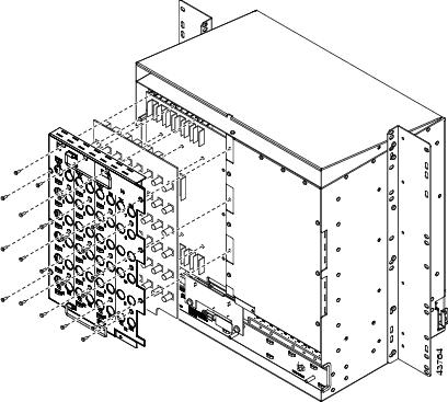
Figure 1-6 shows high-density BNC EIA installation.
Figure 1-6 Installing the High-Density BNC EIA

Step 5 ![]() Return to your originating procedure (NTP).
Return to your originating procedure (NTP).
DLP-A13 Install an SMB EIA
Warning ![]() The covers are an integral part of the safety design of the product. Do not operate the unit without the covers installed.
The covers are an integral part of the safety design of the product. Do not operate the unit without the covers installed.
Step 1 ![]() Remove the SMB card from the packaging. Line up the connectors on the card with the mating connectors on the backplane. Gently push the card until both sets of connectors fit together snugly.
Remove the SMB card from the packaging. Line up the connectors on the card with the mating connectors on the backplane. Gently push the card until both sets of connectors fit together snugly.
Step 2 ![]() Place the EIA panel over the card.
Place the EIA panel over the card.
Step 3 ![]() Insert and tighten the nine perimeter screws (P/N 48-0358) at 8 to 10 lb. (3.6 to 4.5 kg) to secure the cover panel to the backplane.
Insert and tighten the nine perimeter screws (P/N 48-0358) at 8 to 10 lb. (3.6 to 4.5 kg) to secure the cover panel to the backplane.
Step 4 ![]() Insert and tighten the twelve inner screws (P/N 48-0004) at 8 to 10 lb. (3.6 to 4.5 kg) to secure the cover panel to the card and backplane.
Insert and tighten the twelve inner screws (P/N 48-0004) at 8 to 10 lb. (3.6 to 4.5 kg) to secure the cover panel to the card and backplane.
If you are using SMB EIAs to make DS-1 connections, you need the DS-1 electrical interface adapter, commonly referred to as a balun (P/N 15454-WW-14=).
Figure 1-7 shows an SMB EIA installation.
Figure 1-7 Installing the SMB EIA (Use a Balun for DS-1 Connections)

Step 5 ![]() Return to your originating procedure (NTP).
Return to your originating procedure (NTP).
DLP-A14 Install the AMP Champ EIA
Step 1 ![]() Align the AMP Champ panel with the backplane and insert and tighten the nine perimeter screws (P/N 48-0358) at 8 to 10 lb. (3.6 to 4.5 kg).
Align the AMP Champ panel with the backplane and insert and tighten the nine perimeter screws (P/N 48-0358) at 8 to 10 lb. (3.6 to 4.5 kg).
Step 2 ![]() Align an AMP Champ card with the backplane connector and push until it fits snugly. Repeat until you have installed all six AMP Champ cards.
Align an AMP Champ card with the backplane connector and push until it fits snugly. Repeat until you have installed all six AMP Champ cards.
Step 3 ![]() To secure each AMP Champ card to the cover panel, insert and tighten a screw (P/N 48-0003) at the top of each card at 8 to 10 lb. (3.6 to 4.5 kg).
To secure each AMP Champ card to the cover panel, insert and tighten a screw (P/N 48-0003) at the top of each card at 8 to 10 lb. (3.6 to 4.5 kg).
Step 4 ![]() Place the AMP Champ fastening plate along the bottom of the cover panel, and hand-tighten the two thumbscrews.
Place the AMP Champ fastening plate along the bottom of the cover panel, and hand-tighten the two thumbscrews.
Figure 1-8 shows an AMP Champ EIA installation.
Figure 1-8 Installing the AMP Champ EIA

Step 5 ![]() Return to your originating procedure (NTP).
Return to your originating procedure (NTP).
NTP-A6 Install the Power and Ground
Warning ![]() Shut off the power from the power source or turn off the breakers before beginning work.
Shut off the power from the power source or turn off the breakers before beginning work.
Warning ![]() This equipment is intended to be grounded. Ensure that the host is connected to earth ground during normal use.
This equipment is intended to be grounded. Ensure that the host is connected to earth ground during normal use.
Warning ![]() Do not mix conductors of dissimilar metals in a terminal or splicing connector where physical contact occurs (such as copper and aluminum, or copper and copper-clad aluminum), unless the device is suited for the purpose and conditions of use.
Do not mix conductors of dissimilar metals in a terminal or splicing connector where physical contact occurs (such as copper and aluminum, or copper and copper-clad aluminum), unless the device is suited for the purpose and conditions of use.
Warning ![]() Connect the ONS 15454 only to a DC power source that complies with the safety extra-low voltage (SELV) requirements in IEC 60950-based safety standards.
Connect the ONS 15454 only to a DC power source that complies with the safety extra-low voltage (SELV) requirements in IEC 60950-based safety standards.
Warning ![]() The ONS 15454 relies on the protective devices in the building installation to protect against short circuit, overcurrent, and grounding faults. Ensure that the protective devices are properly rated to protect the system, and that they comply with national and local codes.
The ONS 15454 relies on the protective devices in the building installation to protect against short circuit, overcurrent, and grounding faults. Ensure that the protective devices are properly rated to protect the system, and that they comply with national and local codes.
Warning ![]() A readily accessible two-poled disconnect device must be incorporated in the fixed wiring.
A readily accessible two-poled disconnect device must be incorporated in the fixed wiring.
Warning ![]() When installing redundant power feeds, do not use aluminum conductors.
When installing redundant power feeds, do not use aluminum conductors.
Warning ![]() If you use redundant power leads to power the ONS 15454, disconnecting one lead will not remove power from the node.
If you use redundant power leads to power the ONS 15454, disconnecting one lead will not remove power from the node.
Step 1 ![]() Verify one of the following:
Verify one of the following:
•![]() If you have the 15454-SA-ANSI or 15454-SA-HD shelf, a 100-A fuse panel (30-A fuse per shelf minimum) should be installed. If not, install one according to manufacturer's instructions.
If you have the 15454-SA-ANSI or 15454-SA-HD shelf, a 100-A fuse panel (30-A fuse per shelf minimum) should be installed. If not, install one according to manufacturer's instructions.
•![]() If you have the 15454-SA-NEBS3 shelf, a standard 80-A fuse panel (20-A fuse per shelf minimum) should be installed. If not, install one according to manufacturer's instructions.
If you have the 15454-SA-NEBS3 shelf, a standard 80-A fuse panel (20-A fuse per shelf minimum) should be installed. If not, install one according to manufacturer's instructions.
Step 2 ![]() Complete the "DLP-A16 Connect the Office Ground to the ONS 15454" task.
Complete the "DLP-A16 Connect the Office Ground to the ONS 15454" task.
Step 3 ![]() Complete the "DLP-A17 Connect Office Power to the ONS 15454 Shelf" task.
Complete the "DLP-A17 Connect Office Power to the ONS 15454 Shelf" task.
Step 4 ![]() Complete the "DLP-A18 Turn On and Verify Office Power" task.
Complete the "DLP-A18 Turn On and Verify Office Power" task.
Step 5 ![]() Continue with the "A7 Install the Fan-Tray Assembly" procedure.
Continue with the "A7 Install the Fan-Tray Assembly" procedure.
Stop. You have completed this procedure.
DLP-A16 Connect the Office Ground to the ONS 15454
Step 1 ![]() Verify that the office ground cable (#6 AWG stranded) is connected to the top of the bay according to local site practice.
Verify that the office ground cable (#6 AWG stranded) is connected to the top of the bay according to local site practice.
Step 2 ![]() Attach one end of the shelf ground cable (#10 AWG) to the right side of the backplane ground nut. See Figure 1-9 for the location of the ground on the backplane.
Attach one end of the shelf ground cable (#10 AWG) to the right side of the backplane ground nut. See Figure 1-9 for the location of the ground on the backplane.
Note ![]() When terminating a frame ground, use the kep nut provided with the ONS 15454 and tighten it to a torque specification of 31 in-lb. The kep nut provides a frame ground connection that minimizes the possibility of loosening caused by rotation during installation and maintenance activity. The type of prevention the kep nut provides for the frame ground connection is inherently provided by the terminal block for battery and battery return connections.
When terminating a frame ground, use the kep nut provided with the ONS 15454 and tighten it to a torque specification of 31 in-lb. The kep nut provides a frame ground connection that minimizes the possibility of loosening caused by rotation during installation and maintenance activity. The type of prevention the kep nut provides for the frame ground connection is inherently provided by the terminal block for battery and battery return connections.
Figure 1-9 Ground Location on the Backplane

Step 3 ![]() Attach the other end of the shelf ground cable to the bay.
Attach the other end of the shelf ground cable to the bay.
Step 4 ![]() Return to your originating procedure (NTP).
Return to your originating procedure (NTP).
DLP-A17 Connect Office Power to the ONS 15454 Shelf
Warning ![]() Do not apply power to the ONS 15454 until you complete all installation steps and check the continuity of the -48 VDC and return.
Do not apply power to the ONS 15454 until you complete all installation steps and check the continuity of the -48 VDC and return.
Note ![]() The battery return connection is treated as DC-I, as defined in GR-1089-CORE Issue 3.
The battery return connection is treated as DC-I, as defined in GR-1089-CORE Issue 3.
Note ![]() If the system loses power or both TCC2 cards are reset and the system is not provisioned to get the time from a Network Time Protocol/Simple Network Time Protocol (NTP/SNTP) server, you must reset the ONS 15454 clock. After powering down, the date defaults to January 1, 1970, 00:04:15. To reset the clock, see the "NTP-A25 Set Up Name, Date, Time, and Contact Information" procedure on page 4-7.
If the system loses power or both TCC2 cards are reset and the system is not provisioned to get the time from a Network Time Protocol/Simple Network Time Protocol (NTP/SNTP) server, you must reset the ONS 15454 clock. After powering down, the date defaults to January 1, 1970, 00:04:15. To reset the clock, see the "NTP-A25 Set Up Name, Date, Time, and Contact Information" procedure on page 4-7.
If you are using the TCC2 cards, the system clock will be kept running for up to three hours. In this case, no action would be required.
Note ![]() If you encounter problems with the power supply, refer to the Cisco ONS 15454 Troubleshooting Guide.
If you encounter problems with the power supply, refer to the Cisco ONS 15454 Troubleshooting Guide.
Step 1 ![]() Connect the office power according to the fuse panel engineering specifications.
Connect the office power according to the fuse panel engineering specifications.
Step 2 ![]() Measure and cut the cables as needed to reach the ONS 15454 from the fuse panel. Figure 1-10 shows the ONS 15454 power terminals.
Measure and cut the cables as needed to reach the ONS 15454 from the fuse panel. Figure 1-10 shows the ONS 15454 power terminals.
Step 3 ![]() Dress the power according to local site practice.
Dress the power according to local site practice.
Warning ![]() When installing the ONS 15454, the ground connection must always be made first and disconnected last.
When installing the ONS 15454, the ground connection must always be made first and disconnected last.
Figure 1-10 Cisco ONS 15454 Power Terminals

Step 4 ![]() Remove or loosen the #8 power terminal screws on the ONS 15454. To avoid confusion, label the cables connected to the BAT1/RET1 (A) power terminals as 1, and the cables connected to the BAT2/RET2 (B) power terminals as 2.
Remove or loosen the #8 power terminal screws on the ONS 15454. To avoid confusion, label the cables connected to the BAT1/RET1 (A) power terminals as 1, and the cables connected to the BAT2/RET2 (B) power terminals as 2.
Note ![]() Use only pressure terminal connectors, such as ring and fork types, when terminating the battery, battery return, and frame ground conductors.
Use only pressure terminal connectors, such as ring and fork types, when terminating the battery, battery return, and frame ground conductors.
Step 5 ![]() Strip 1/2 inch (12.7 mm) of insulation from all power cables that you will use.
Strip 1/2 inch (12.7 mm) of insulation from all power cables that you will use.
Step 6 ![]() Crimp the lugs onto the ends of all power leads.
Crimp the lugs onto the ends of all power leads.
Note ![]() When terminating battery and battery return connections as shown in Figure 1-10, follow a torque specification of 10 in-lb.
When terminating battery and battery return connections as shown in Figure 1-10, follow a torque specification of 10 in-lb.
Step 7 ![]() Terminate the return 1 lead to the RET1 backplane terminal. Use oxidation-prevention grease to keep connections noncorrosive.
Terminate the return 1 lead to the RET1 backplane terminal. Use oxidation-prevention grease to keep connections noncorrosive.
Warning ![]() Do not secure multiple connectors with the same bolt assembly.
Do not secure multiple connectors with the same bolt assembly.
Step 8 ![]() Terminate the negative 1 lead to the negative BAT1 backplane power terminal. Use oxidation prevention grease to keep connections noncorrosive.
Terminate the negative 1 lead to the negative BAT1 backplane power terminal. Use oxidation prevention grease to keep connections noncorrosive.
Step 9 ![]() If you use redundant power leads, terminate the return 2 lead to the positive RET2 terminal on the ONS 15454. Terminate the negative 2 lead to the negative BAT2 terminal on the ONS 15454. Use oxidation-preventative grease to keep connections noncorrosive.
If you use redundant power leads, terminate the return 2 lead to the positive RET2 terminal on the ONS 15454. Terminate the negative 2 lead to the negative BAT2 terminal on the ONS 15454. Use oxidation-preventative grease to keep connections noncorrosive.
Step 10 ![]() Route the cables out below the power terminals using the plastic cable clamp, as shown in Figure 1-10.
Route the cables out below the power terminals using the plastic cable clamp, as shown in Figure 1-10.
Step 11 ![]() Return to your originating procedure (NTP).
Return to your originating procedure (NTP).
DLP-A18 Turn On and Verify Office Power
Purpose |
This task measures the power to verify correct power and returns. |
Tools/Equipment |
Voltmeter |
Prerequisite Procedures |
A16 Connect the Office Ground to the ONS 15454 |
Required/As Needed |
Required |
Onsite/Remote |
Onsite |
Security Level |
None |
Step 1 ![]() Using a voltmeter, verify the office battery and ground at the following points on the fuse and alarm panel:
Using a voltmeter, verify the office battery and ground at the following points on the fuse and alarm panel:
a. ![]() To verify the power, place the black test lead of the voltmeter to the frame ground. Place the red test lead on the A-side connection and verify that it is between -40.5 VDC and -57 VDC. Place the red test lead on the B-side connection and verify that it is between -40.5 VDC and -57 VDC.
To verify the power, place the black test lead of the voltmeter to the frame ground. Place the red test lead on the A-side connection and verify that it is between -40.5 VDC and -57 VDC. Place the red test lead on the B-side connection and verify that it is between -40.5 VDC and -57 VDC.
Note ![]() The voltages -40.5 VDC and -57 VDC are, respectively, the minimum and maximum voltages required to power the chassis.
The voltages -40.5 VDC and -57 VDC are, respectively, the minimum and maximum voltages required to power the chassis.
b. ![]() To verify the ground, place the black test lead of the voltmeter to the frame ground. Place the red test lead on the A-side return ground and verify that no voltage is present. Place the red test lead on the B-side return ground and verify that no voltage is present.
To verify the ground, place the black test lead of the voltmeter to the frame ground. Place the red test lead on the A-side return ground and verify that no voltage is present. Place the red test lead on the B-side return ground and verify that no voltage is present.
Step 2 ![]() Complete one of the following to power up the node:
Complete one of the following to power up the node:
•![]() If you are using a 80-A fuse panel, insert a 20-A fuse into the fuse position according to site practice.
If you are using a 80-A fuse panel, insert a 20-A fuse into the fuse position according to site practice.
•![]() If you are using a 100-A fuse panel, insert a 30-A fuse into the fuse position according to site practice.
If you are using a 100-A fuse panel, insert a 30-A fuse into the fuse position according to site practice.
Step 3 ![]() Using a voltmeter, verify the shelf for -48 VDC battery and ground:
Using a voltmeter, verify the shelf for -48 VDC battery and ground:
a. ![]() To verify the A-side of the shelf, place the black lead of the voltmeter to the frame ground. Place the red test lead to the BAT1 (A-side battery connection) red cable. Verify that it reads between -40.5 VDC and -57 VDC. Then place the red test lead of the voltmeter to the RET1 (A-side return ground) black cable and verify that no voltage is present.
To verify the A-side of the shelf, place the black lead of the voltmeter to the frame ground. Place the red test lead to the BAT1 (A-side battery connection) red cable. Verify that it reads between -40.5 VDC and -57 VDC. Then place the red test lead of the voltmeter to the RET1 (A-side return ground) black cable and verify that no voltage is present.
Note ![]() The voltages -40.5 VDC and -57 VDC are, respectively, the minimum and maximum voltages required to power the chassis.
The voltages -40.5 VDC and -57 VDC are, respectively, the minimum and maximum voltages required to power the chassis.
b. ![]() To verify the B-side of the shelf, place the black test lead of the voltmeter to the frame ground. Place the red test lead to the BAT2 (B-side battery connection) red cable. Verify that it reads between -40.5 VDC and -57 VDC. Then, place the red test lead of the voltmeter to the RET2 (B-side return ground) black cable and verify that no voltage is present.
To verify the B-side of the shelf, place the black test lead of the voltmeter to the frame ground. Place the red test lead to the BAT2 (B-side battery connection) red cable. Verify that it reads between -40.5 VDC and -57 VDC. Then, place the red test lead of the voltmeter to the RET2 (B-side return ground) black cable and verify that no voltage is present.
Step 4 ![]() Return to your originating procedure (NTP).
Return to your originating procedure (NTP).
NTP-A7 Install the Fan-Tray Assembly
Purpose |
This procedure installs the fan-tray assembly. |
Tools/Equipment |
#2 Phillips screwdriver Medium slot-head screwdriver Small slot-head screwdriver |
Prerequisite Procedures |
A3 Open and Remove the Front Door |
Required/As Needed |
Required |
Onsite/Remote |
Onsite |
Security Level |
None |
Note ![]() If you are installing the ONS 15454 in an outside plant cabinet, remove the air filter to provide maximum cooling capabilities and to comply with GR-487-CORE.
If you are installing the ONS 15454 in an outside plant cabinet, remove the air filter to provide maximum cooling capabilities and to comply with GR-487-CORE.
Note ![]() To install the fan-tray assembly, it is not necessary to move any of the cable-management facilities.
To install the fan-tray assembly, it is not necessary to move any of the cable-management facilities.
Step 1 ![]() Install the air filter. The air filter can be installed internally between the fan tray and shelf assembly, or externally by mounting the air filter bracket on the bottom of the shelf assembly. Slide the air filter into the bracket.
Install the air filter. The air filter can be installed internally between the fan tray and shelf assembly, or externally by mounting the air filter bracket on the bottom of the shelf assembly. Slide the air filter into the bracket.
Step 2 ![]() Slide the fan tray into the shelf assembly until the electrical plug at the rear of the tray plugs into the corresponding receptacle on the backplane.
Slide the fan tray into the shelf assembly until the electrical plug at the rear of the tray plugs into the corresponding receptacle on the backplane.
Step 3 ![]() To verify that the tray has plugged into the backplane, look at the fan tray and listen to determine that the fans are running.
To verify that the tray has plugged into the backplane, look at the fan tray and listen to determine that the fans are running.
Figure 1-11 shows the location of the fan tray.
Figure 1-11 Installing the Fan-Tray Assembly

Step 4 ![]() Continue with the "A119 Install the Alarm Expansion Panel" procedure if you plan to install an Alarm Expansion Panel (AEP). If not, continue with the "A8 Attach Wires to Alarm, Timing, LAN, and Craft Pin Connections" procedure.
Continue with the "A119 Install the Alarm Expansion Panel" procedure if you plan to install an Alarm Expansion Panel (AEP). If not, continue with the "A8 Attach Wires to Alarm, Timing, LAN, and Craft Pin Connections" procedure.
Stop. You have completed this procedure.
NTP-A119 Install the Alarm Expansion Panel
Note ![]() The AIC-I card provides direct alarm contacts (external alarm inputs and external control outputs). In the ANSI shelf, these AIC-I alarm contacts are routed through the backplane to wire-wrap pins accessible from the back of the shelf. When you install an AEP, the direct AIC-I alarm contacts cannot be used. Only the AEP alarm contacts can be used.
The AIC-I card provides direct alarm contacts (external alarm inputs and external control outputs). In the ANSI shelf, these AIC-I alarm contacts are routed through the backplane to wire-wrap pins accessible from the back of the shelf. When you install an AEP, the direct AIC-I alarm contacts cannot be used. Only the AEP alarm contacts can be used.
Step 1 ![]() Remove the two backplane screws. Replace the two screws with standoffs. Insert the longer standoff on the left, and the shorter standoff on the right (Figure 1-12).
Remove the two backplane screws. Replace the two screws with standoffs. Insert the longer standoff on the left, and the shorter standoff on the right (Figure 1-12).
Figure 1-12 Replace Backplane Screws with Standoffs

Step 2 ![]() Attach the remaining two standoffs on either side of the backplane (Figure 1-13).
Attach the remaining two standoffs on either side of the backplane (Figure 1-13).
Step 3 ![]() Position the AEP board over the standoffs.
Position the AEP board over the standoffs.
Figure 1-13 Installing Standoffs and the AEP
Step 4 ![]() Insert and tighten three screws to secure the AEP to the backplane.
Insert and tighten three screws to secure the AEP to the backplane.
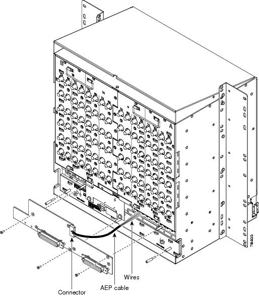
Step 5 ![]() Connect the AEP cable to the backplane and AEP:
Connect the AEP cable to the backplane and AEP:
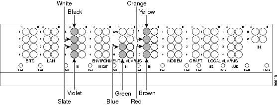
a. ![]() Connect the 10 colored wires to the wire-wrap pins on the backplane. Figure 1-14 shows where the cable wires are connected. Table 1-1 shows AEP and AIC-I signals that each wire carries.
Connect the 10 colored wires to the wire-wrap pins on the backplane. Figure 1-14 shows where the cable wires are connected. Table 1-1 shows AEP and AIC-I signals that each wire carries.
b. ![]() Plug the other end of the AEP cable into AEP connector port. The brown pin is on the top.
Plug the other end of the AEP cable into AEP connector port. The brown pin is on the top.
Figure 1-14 AEP Wire-Wrap Connections to Backplane Pins
Step 6 ![]() Continue with the "A8 Attach Wires to Alarm, Timing, LAN, and Craft Pin Connections" procedure.
Continue with the "A8 Attach Wires to Alarm, Timing, LAN, and Craft Pin Connections" procedure.
Stop. You have completed this procedure.
NTP-A8 Attach Wires to Alarm, Timing, LAN, and Craft Pin Connections
Step 1 ![]() Complete the "DLP-A19 Install Alarm Wires on the Backplane" task if you are using an AIC or AIC-I card and are not using an AEP.
Complete the "DLP-A19 Install Alarm Wires on the Backplane" task if you are using an AIC or AIC-I card and are not using an AEP.
Step 2 ![]() Complete the "DLP-A20 Install Timing Wires on the Backplane" task as needed. Timing wires are necessary to provision external timing.
Complete the "DLP-A20 Install Timing Wires on the Backplane" task as needed. Timing wires are necessary to provision external timing.
Step 3 ![]() Complete the "DLP-A21 Install LAN Wires on the Backplane" task as needed. LAN wires (or the LAN port on the TCC2) are necessary to create an external LAN connection.
Complete the "DLP-A21 Install LAN Wires on the Backplane" task as needed. LAN wires (or the LAN port on the TCC2) are necessary to create an external LAN connection.
Step 4 ![]() Complete the "DLP-A22 Install the TL1 Craft Interface" task as needed. Craft wires (or the EIA/TIA-232 port on the TCC2) are required to access TL1 using the craft interface.
Complete the "DLP-A22 Install the TL1 Craft Interface" task as needed. Craft wires (or the EIA/TIA-232 port on the TCC2) are required to access TL1 using the craft interface.
Caution
Step 5 ![]() Complete one of the following:
Complete one of the following:
•![]() If you installed an alarm expansion panel (AEP), continue with the "A120 Install an External Wire-Wrap Panel to the AEP" procedure.
If you installed an alarm expansion panel (AEP), continue with the "A120 Install an External Wire-Wrap Panel to the AEP" procedure.
•![]() If you did not install an AEP and you plan to install electrical cards, continue with the "A9 Install the Electrical Card Cables on the Backplane" procedure.
If you did not install an AEP and you plan to install electrical cards, continue with the "A9 Install the Electrical Card Cables on the Backplane" procedure.
•![]() If you did not install an AEP and do not plan to install electrical cards, continue with the "A11 Install the Rear Cover" procedure.
If you did not install an AEP and do not plan to install electrical cards, continue with the "A11 Install the Rear Cover" procedure.
Stop. You have completed this procedure.
DLP-A19 Install Alarm Wires on the Backplane
Step 1 ![]() Using 100-ohm shielded BITS clock cable pair #22 or #24 AWG (0.51 mm² or 0.64 mm²) twisted-pair T1-type wires, wrap the alarm wires on the appropriate wire-wrap pins according to local site practice. Ground the shield of the BITS Input cable at the BITS end. For BITS Output, wrap the ground shield of the BITS cable to the frame ground pin (FG1) located below the column of BITS Pins.
Using 100-ohm shielded BITS clock cable pair #22 or #24 AWG (0.51 mm² or 0.64 mm²) twisted-pair T1-type wires, wrap the alarm wires on the appropriate wire-wrap pins according to local site practice. Ground the shield of the BITS Input cable at the BITS end. For BITS Output, wrap the ground shield of the BITS cable to the frame ground pin (FG1) located below the column of BITS Pins.
Figure 1-15 shows alarm pin assignments for the AIC-I in the Release 3.4 or higher ONS 15454 backplane and Figure 1-16 calls out the environmental alarm pins onthat backplane. Figure 1-17 shows alarm pin assignments for the AIC in a shelf for Release 3.3 and earlier.
Note ![]() The AIC-I requires a shelf assembly running Software Release 3.4.0 or later. The backplane of the ANSI shelf contains a wire-wrap field with pin assignment according to the layout in Figure 1-15. The shelf assembly may be an existing shelf that has been upgraded to 3.4. In this case the backplane pin labeling will appear as indicated in Figure 1-17 but you must use the pin assignments provided by the AIC-I as shown in Figure 1-15.
The AIC-I requires a shelf assembly running Software Release 3.4.0 or later. The backplane of the ANSI shelf contains a wire-wrap field with pin assignment according to the layout in Figure 1-15. The shelf assembly may be an existing shelf that has been upgraded to 3.4. In this case the backplane pin labeling will appear as indicated in Figure 1-17 but you must use the pin assignments provided by the AIC-I as shown in Figure 1-15.
For information about attaching ferrites to wire-wrap pin fields, see the "DLP-A31 Attach Ferrites to Wire-Wrap Pin Fields" task.
Figure 1-15 Cisco ONS 15454 Backplane Pinouts (Release 3.4 or Later)

Figure 1-16 Highlighted Environmental Alarms

Figure 1-17 Cisco ONS 15454 Backplane Pinouts (Release 3.3 or Earlier)

Note ![]() The X.25, Modem, and TBOS pin fields are not active on either pin field.
The X.25, Modem, and TBOS pin fields are not active on either pin field.
Step 2 ![]() Return to your originating procedure (NTP).
Return to your originating procedure (NTP).
DLP-A20 Install Timing Wires on the Backplane
Step 1 ![]() Using 100-ohm shielded BITS clock cable pair #22 or #24 AWG (0.51 mm² or 0.64 mm²), twisted-pair T1-type, wrap the clock wires on the appropriate wire-wrap pins according to local site practice.
Using 100-ohm shielded BITS clock cable pair #22 or #24 AWG (0.51 mm² or 0.64 mm²), twisted-pair T1-type, wrap the clock wires on the appropriate wire-wrap pins according to local site practice.
Ground the shield of the BITS input cable at the BITS end. For BITS output, wrap the ground shield of the BITS cable to the frame ground pin (FG1) located beneath the column of BITS Pins. Table 1-2 lists the pin assignments for the BITS timing pin fields.
Note ![]() For more detailed information about timing, refer to the Cisco ONS 15454 Reference Manual. To set up system timing, see the "NTP-A28 Set Up Timing" procedure on page 4-22.
For more detailed information about timing, refer to the Cisco ONS 15454 Reference Manual. To set up system timing, see the "NTP-A28 Set Up Timing" procedure on page 4-22.
Step 2 ![]() Return to your originating procedure (NTP).
Return to your originating procedure (NTP).
DLP-A21 Install LAN Wires on the Backplane
Note ![]() Rather than using the LAN wires, you can use the LAN connection port on the TCC2 if preferred. Use either the backplane connection or the TCC2 front connection. You cannot use the LAN backplane pins and the LAN connection port on the TCC2 simultaneously; however, it is possible for you to make a direct connection from a computer to the LAN connection port on the TCC2 while the LAN backplane pins are in use as long as the computer that is connected directly to the TCC2 is not connected to a LAN.
Rather than using the LAN wires, you can use the LAN connection port on the TCC2 if preferred. Use either the backplane connection or the TCC2 front connection. You cannot use the LAN backplane pins and the LAN connection port on the TCC2 simultaneously; however, it is possible for you to make a direct connection from a computer to the LAN connection port on the TCC2 while the LAN backplane pins are in use as long as the computer that is connected directly to the TCC2 is not connected to a LAN.
Step 1 ![]() Using #22 or #24 AWG (0.51 mm² or 0.64 mm²) wire or CAT5 UTP Ethernet cable, wrap the wires on the appropriate wire-wrap pins according to local site practice.
Using #22 or #24 AWG (0.51 mm² or 0.64 mm²) wire or CAT5 UTP Ethernet cable, wrap the wires on the appropriate wire-wrap pins according to local site practice.
A frame ground pin is located beneath each pin field (FG2 for the LAN pin field). Wrap the ground shield of the LAN interface cable to the frame ground pin. Table 1-3 shows the LAN pin assignments.
Note ![]() The TCC2 does not support Ethernet polarity detection. If your Ethernet connection has incorrect polarity (this can only occur with cables that have the receive wire pairs flipped), a "Lan Connection Polarity Reversed" condition is raised. This condition usually occurs during an upgrade or initial node deployment. To correct the situation, ensure that your Ethernet cable has the correct mapping of the wire-wrap pins.
The TCC2 does not support Ethernet polarity detection. If your Ethernet connection has incorrect polarity (this can only occur with cables that have the receive wire pairs flipped), a "Lan Connection Polarity Reversed" condition is raised. This condition usually occurs during an upgrade or initial node deployment. To correct the situation, ensure that your Ethernet cable has the correct mapping of the wire-wrap pins.
Step 2 ![]() Return to your originating procedure (NTP).
Return to your originating procedure (NTP).
DLP-A22 Install the TL1 Craft Interface
Note ![]() Rather than using the craft pins, you can use a LAN cable connected to the TCC2 EIA/TIA-232 port to access a TL1 craft interface.
Rather than using the craft pins, you can use a LAN cable connected to the TCC2 EIA/TIA-232 port to access a TL1 craft interface.
Step 1 ![]() Using #22 or #24 AWG (0.51 mm² or 0.64 mm²) wire, wrap the craft interface wires on the appropriate wire-wrap pins according to local site practice.
Using #22 or #24 AWG (0.51 mm² or 0.64 mm²) wire, wrap the craft interface wires on the appropriate wire-wrap pins according to local site practice.
Note ![]() For information about attaching ferrites to wire-wrap pin fields, see the "DLP-A31 Attach Ferrites to Wire-Wrap Pin Fields" task.
For information about attaching ferrites to wire-wrap pin fields, see the "DLP-A31 Attach Ferrites to Wire-Wrap Pin Fields" task.
Step 2 ![]() Wrap the ground shield of the craft interface cable to the frame-ground pin.
Wrap the ground shield of the craft interface cable to the frame-ground pin.
Wrap the ground wire of your computer cable to pin A3 on the craft pin field. Table 1-4 shows the pin assignments for the CRAFT pin field.
Note ![]() You cannot use the craft backplane pins and the EIA/TIA-232 port on the TCC2 card simultaneously. Using a combination prevents access to the node or causes a loss in connectivity.
You cannot use the craft backplane pins and the EIA/TIA-232 port on the TCC2 card simultaneously. Using a combination prevents access to the node or causes a loss in connectivity.
|
|
|
|
|---|---|---|
Craft |
A1 |
Receive |
A2 |
Transmit |
|
A3 |
Ground |
|
A4 |
DTR |
Step 3 ![]() Return to your originating procedure (NTP).
Return to your originating procedure (NTP).
NTP-A120 Install an External Wire-Wrap Panel to the AEP
Step 1 ![]() Position the lower cover over the AEP. Make sure that the AEP AMP Champ connectors protrude through the cutouts in the lower cover (Figure 1-18).
Position the lower cover over the AEP. Make sure that the AEP AMP Champ connectors protrude through the cutouts in the lower cover (Figure 1-18).
Figure 1-18 Installing the AEP Cover
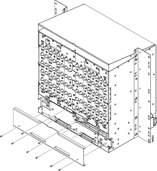
Step 2 ![]() Insert and tighten the eight screws to secure the AEP cover to the AEP.
Insert and tighten the eight screws to secure the AEP cover to the AEP.
Step 3 ![]() Connect the cables from the external wire-wrap panel to the AMP Champ connectors on the AEP. Table 1-5 lists the alarm input pin assignments.
Connect the cables from the external wire-wrap panel to the AMP Champ connectors on the AEP. Table 1-5 lists the alarm input pin assignments.
Table 1-6 lists the alarm output pin assignments.
Figure 1-19 illustrates the alarm input connectors.
Figure 1-19 Alarm Input Connector

Figure 1-20 illustrates the alarm output connectors.
Figure 1-20 Alarm Output Connector
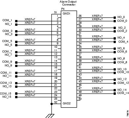
Step 4 ![]() Complete one of the following:
Complete one of the following:
•![]() If you plan to install electrical cards, continue with the "A9 Install the Electrical Card Cables on the Backplane" procedure.
If you plan to install electrical cards, continue with the "A9 Install the Electrical Card Cables on the Backplane" procedure.
•![]() If you do not plan to install electrical cards, continue with the "A11 Install the Rear Cover" procedure.
If you do not plan to install electrical cards, continue with the "A11 Install the Rear Cover" procedure.
Stop. You have completed this procedure.
NTP-A9 Install the Electrical Card Cables on the Backplane
Note ![]() Refer to the Cisco ONS 15454 Reference Manual for more information about EIAs.
Refer to the Cisco ONS 15454 Reference Manual for more information about EIAs.
Step 1 ![]() Complete the "DLP-A530 Install the Tie-Down Bar" task as needed for routing the electrical cables you will install.
Complete the "DLP-A530 Install the Tie-Down Bar" task as needed for routing the electrical cables you will install.
Step 2 ![]() Complete the "DLP-A23 Install DS-1 Cables Using Electrical Interface Adapters (Balun)" task as needed. Baluns are used on SMB EIAs to properly terminate DS-1 signals.
Complete the "DLP-A23 Install DS-1 Cables Using Electrical Interface Adapters (Balun)" task as needed. Baluns are used on SMB EIAs to properly terminate DS-1 signals.
Step 3 ![]() To install DS-1 cables using AMP Champ cables, complete the "DLP-A24 Install DS-1 AMP Champ Cables on the AMP Champ EIA" task.
To install DS-1 cables using AMP Champ cables, complete the "DLP-A24 Install DS-1 AMP Champ Cables on the AMP Champ EIA" task.
Step 4 ![]() Complete the "DLP-A25 Install Coaxial Cable With BNC Connectors" task as needed.
Complete the "DLP-A25 Install Coaxial Cable With BNC Connectors" task as needed.
Step 5 ![]() Complete the "DLP-A26 Install Coaxial Cable With High-Density BNC Connectors" task as needed.
Complete the "DLP-A26 Install Coaxial Cable With High-Density BNC Connectors" task as needed.
Step 6 ![]() Complete the "DLP-A27 Install Coaxial Cable with SMB Connectors" task as needed.
Complete the "DLP-A27 Install Coaxial Cable with SMB Connectors" task as needed.
Step 7 ![]() Continue with the "A10 Route Electrical Cables" procedure.
Continue with the "A10 Route Electrical Cables" procedure.
Stop. You have completed this procedure.
DLP-A530 Install the Tie-Down Bar
Purpose |
This task installs the tie-down bar used to secure cabling on the rear of the ONS 15454. The tie-down bar can be used to provide a diverse path for redundant power feeds and cables. |
Tools/Equipment |
Tie-down bar Screws (4) |
Prerequisite Procedures |
A5 Mount the Shelf Assembly in a Rack (One Person) |
Required/As Needed |
As needed |
Onsite/Remote |
Onsite |
Security Level |
None |
Step 1 ![]() Align the ends of the tie-down bar with the four screw holes located 1 RU below the ONS 15454.
Align the ends of the tie-down bar with the four screw holes located 1 RU below the ONS 15454.
Figure 1-21 shows the tie-down bar, the ONS 15454, and the rack.
Figure 1-21 Tie-Down Bar

Step 2 ![]() Install the four screws into the rack.
Install the four screws into the rack.
Step 3 ![]() Return to your originating procedure (NTP).
Return to your originating procedure (NTP).
DLP-A23 Install DS-1 Cables Using Electrical Interface Adapters (Balun)
Note ![]() All DS-1 cables connected to the ONS 15454 DS-1 ports must terminate with twisted-pair cables to connect to the DS-1 electrical interface adapter. The DS-1 electrical interface adapters project 1.72 inches (43.7 mm) beyond the SMB EIA. Refer to the Cisco ONS 15454 Reference Manual for more information.
All DS-1 cables connected to the ONS 15454 DS-1 ports must terminate with twisted-pair cables to connect to the DS-1 electrical interface adapter. The DS-1 electrical interface adapters project 1.72 inches (43.7 mm) beyond the SMB EIA. Refer to the Cisco ONS 15454 Reference Manual for more information.
Step 1 ![]() Attach the SMB connector on an adapter to the SMB connector for the port's transmit pair on the backplane.
Attach the SMB connector on an adapter to the SMB connector for the port's transmit pair on the backplane.
Step 2 ![]() Attach the SMB connector on an adapter to the SMB connector for the port's receive pair on the backplane.
Attach the SMB connector on an adapter to the SMB connector for the port's receive pair on the backplane.
Step 3 ![]() Terminate the DS-1 transmit and receive cables for the port to the wire-wrap posts on the adapter:
Terminate the DS-1 transmit and receive cables for the port to the wire-wrap posts on the adapter:
a. ![]() Using a wire-wrap tool, connect the receive cables to the receive adapter pins on the backplane connector for the desired port.
Using a wire-wrap tool, connect the receive cables to the receive adapter pins on the backplane connector for the desired port.
b. ![]() Connect the transmit cables to the transmit adapter pins on the backplane connector for the desired port.
Connect the transmit cables to the transmit adapter pins on the backplane connector for the desired port.
c. ![]() Terminate the shield ground wire on the DS-1 cable to ground according to local site practice.
Terminate the shield ground wire on the DS-1 cable to ground according to local site practice.
Note ![]() If you put DS1N-14 cards in Slots 3 and 15 to form 1:N protection groups, do not wire Slots 3 and 15 for DS-1 electrical interface adapters.
If you put DS1N-14 cards in Slots 3 and 15 to form 1:N protection groups, do not wire Slots 3 and 15 for DS-1 electrical interface adapters.
Figure 1-22 shows a ONS 15454 backplane with an SMB EIA. DS-1 electrical interface adapters are attached on both sides of the shelf assembly to create DS-1 twisted-pair termination points.
Figure 1-22 Backplane with an SMB EIA for DS-1 Cables

Step 4 ![]() Return to your originating procedure (NTP).
Return to your originating procedure (NTP).
DLP-A24 Install DS-1 AMP Champ Cables on the AMP Champ EIA
Step 1 ![]() Prepare a 56-wire cable for each DS1-14/DS1N-14 card you will install in the shelf assembly.
Prepare a 56-wire cable for each DS1-14/DS1N-14 card you will install in the shelf assembly.
Step 2 ![]() Connect the male AMP Champ connector on the cable to the female AMP Champ connector on the ONS 15454 backplane.
Connect the male AMP Champ connector on the cable to the female AMP Champ connector on the ONS 15454 backplane.
Step 3 ![]() Use the clips on the male AMP Champ connector to secure the connection.
Use the clips on the male AMP Champ connector to secure the connection.
The female connector has grooves on the outside edge for snapping the clips into place.
Table 1-7 shows the pin assignments for the AMP Champ connectors on the ONS 15454 AMP Champ EIA.
Note ![]() In Table 1-7, the shaded area corresponds to the white/orange binder group. A binder group is a set of 25 pairs of wires coded with an industry-standard color scheme.
In Table 1-7, the shaded area corresponds to the white/orange binder group. A binder group is a set of 25 pairs of wires coded with an industry-standard color scheme.
|
|
|
|
|
|
|
|
|
|---|---|---|---|---|---|---|---|
Tx Tip 1 |
1 |
33 |
Tx Ring 1 |
Rx Tip 1 |
17 |
49 |
Rx Ring 1 |
Tx Tip 2 white/orange |
2 |
34 |
Tx Ring 2 |
Rx Tip 2 |
18 |
50 |
Rx Ring 2 |
Tx Tip 3 |
3 |
35 |
Tx Ring 3 |
Rx Tip 3 |
19 |
51 |
Rx Ring 3 |
Tx Tip 4 |
4 |
36 |
Tx Ring 4 |
Rx Tip 4 |
20 |
52 |
Rx Ring 4 |
Tx Tip 5 |
5 |
37 |
Tx Ring 5 |
Rx Tip 5 |
21 |
53 |
Rx Ring 5 |
Tx Tip 6 |
6 |
38 |
Tx Ring 6 |
Rx Tip 6 |
22 |
54 |
Rx Ring 6 |
Tx Tip 7 |
7 |
39 |
Tx Ring 7 |
Rx Tip 7 |
23 |
55 |
Rx Ring 7 |
Tx Tip 8 |
8 |
40 |
Tx Ring 8 |
Rx Tip 8 |
24 |
56 |
Rx Ring 8 |
Tx Tip 9 |
9 |
41 |
Tx Ring 9 |
Rx Tip 9 |
25 |
57 |
Rx Ring 9 |
Tx Tip 10 |
10 |
42 |
Tx Ring 10 |
Rx Tip 10 1 |
26 |
58 |
Rx Ring 10 |
Tx Tip 11 |
11 |
43 |
Tx Ring 11 |
Rx Tip 11 |
27 |
59 |
Rx Ring 11 |
Tx Tip 12 |
12 |
44 |
Tx Ring 12 |
Rx Tip 12 |
28 |
60 |
Rx Ring 12 |
Tx Tip 13 |
13 |
45 |
Tx Ring 13 |
Rx Tip 13 |
29 |
61 |
Rx Ring 13 |
Tx Tip 14 |
14 |
46 |
Tx Ring 14 |
Rx Tip 14 |
30 |
62 |
Rx Ring 14 |
Tx Spare0+ Not applicable |
15 |
47 |
Tx Spare0- Not applicable |
Rx Spare0+ Not applicable |
31 |
63 |
Rx Spare0- Not applicable |
Tx Spare1+ Not applicable |
16 |
48 |
Tx Spare1- Not applicable |
Rx Spare1+ Not applicable |
32 |
64 |
Rx Spare1- Not applicable |
1 Shaded areas correspond to the white/orange binder group. A binder group is a set of 25 pairs of wires coded with an industry-standard color scheme. |
Table 1-8 shows the pin assignments for the AMP Champ connectors on the ONS 15454 AMP Champ EIA for a shielded DS-1 cable.
Step 4 ![]() Return to your originating procedure (NTP).
Return to your originating procedure (NTP).
DLP-A25 Install Coaxial Cable With BNC Connectors
Purpose |
This task installs the coaxial cable with BNC connectors. |
Tools/Equipment |
None |
Prerequisite Procedures |
|
Required/As Needed |
As needed |
Onsite/Remote |
Onsite |
Security Level |
None |
Step 1 ![]() Place the BNC cable connector over the desired connection point on the backplane.
Place the BNC cable connector over the desired connection point on the backplane.
Figure 1-23 shows how to connect a coaxial cable to the BNC EIA using a right-angle BNC cable connector.
Figure 1-23 Using a Right-Angle Connector to Install Coaxial Cable with BNC Connectors

Step 2 ![]() Position the cable connector so that the slot in the connector is over the corresponding notch at the backplane connection point.
Position the cable connector so that the slot in the connector is over the corresponding notch at the backplane connection point.
Step 3 ![]() Gently push the connector down until the notch backplane connector slides into the slot on the cable connector.
Gently push the connector down until the notch backplane connector slides into the slot on the cable connector.
Step 4 ![]() Turn the cable connector clockwise to lock it into place.
Turn the cable connector clockwise to lock it into place.
Step 5 ![]() Tie wrap or lace the cables to the EIA according to Telcordia standards (GR-1275-CORE) or local site practice.
Tie wrap or lace the cables to the EIA according to Telcordia standards (GR-1275-CORE) or local site practice.
Step 6 ![]() Route the cables to the nearest side of the shelf assembly through the side cutouts according to local site practice. The rubber-coated edges of the side cutouts prevent the cables from chafing.
Route the cables to the nearest side of the shelf assembly through the side cutouts according to local site practice. The rubber-coated edges of the side cutouts prevent the cables from chafing.
Warning ![]() Metallic interfaces for connection to outside plant lines (such as T1/E1/T3/E3, etc.) must be connected through a registered or approved device such as CSU/DSU or NT1.
Metallic interfaces for connection to outside plant lines (such as T1/E1/T3/E3, etc.) must be connected through a registered or approved device such as CSU/DSU or NT1.
Step 7 ![]() Label all cables at each end of the connection to avoid confusion with cables that are similar in appearance.
Label all cables at each end of the connection to avoid confusion with cables that are similar in appearance.
Step 8 ![]() Return to your originating procedure (NTP).
Return to your originating procedure (NTP).
DLP-A26 Install Coaxial Cable With High-Density BNC Connectors
Step 1 ![]() Place the cable connector over the desired connection point on the backplane.
Place the cable connector over the desired connection point on the backplane.
Step 2 ![]() Using the BNC insertion tool, position the cable connector so that the slot in the connector is over the corresponding notch at the backplane connection point.
Using the BNC insertion tool, position the cable connector so that the slot in the connector is over the corresponding notch at the backplane connection point.
Step 3 ![]() Gently push the connector down until the notch backplane connector slides into the slot on the cable connector.
Gently push the connector down until the notch backplane connector slides into the slot on the cable connector.
Step 4 ![]() Turn the cable connector clockwise to lock it into place.
Turn the cable connector clockwise to lock it into place.
Step 5 ![]() Tie wrap or lace the cables to the EIA according to Telcordia standards (GR-1275-CORE) or local site practice.
Tie wrap or lace the cables to the EIA according to Telcordia standards (GR-1275-CORE) or local site practice.
Step 6 ![]() Route the cables to the nearest side of the shelf assembly through the side cutouts according to local site practice.
Route the cables to the nearest side of the shelf assembly through the side cutouts according to local site practice.
Warning ![]() Metallic interfaces for connection to outside plant lines (such as T1/E1/T3/E3, etc.) must be connected through a registered or approved device such as CSU/DSU or NT1.
Metallic interfaces for connection to outside plant lines (such as T1/E1/T3/E3, etc.) must be connected through a registered or approved device such as CSU/DSU or NT1.
The rubber-coated edges of the side cutouts prevent the cables from chafing.
Step 7 ![]() Return to your originating procedure (NTP).
Return to your originating procedure (NTP).
DLP-A27 Install Coaxial Cable with SMB Connectors
Purpose |
This task installs the coaxial cable with SMB connectors. |
Tools/Equipment |
SMB cable connector |
Prerequisite Procedures |
|
Required/As Needed |
As needed |
Onsite/Remote |
Onsite |
Security Level |
None |
Step 1 ![]() Place the SMB cable connector over the desired connection point on the backplane (Figure 1-24).
Place the SMB cable connector over the desired connection point on the backplane (Figure 1-24).
Step 2 ![]() Gently push the connector until it clicks into place.
Gently push the connector until it clicks into place.
Step 3 ![]() Tie wrap or lace the cables to the EIA according to Telcordia standards (GR-1275-CORE) or local site practice.
Tie wrap or lace the cables to the EIA according to Telcordia standards (GR-1275-CORE) or local site practice.
Step 4 ![]() Route the cables to the nearest side of the shelf assembly into rack runs according to local site practice.
Route the cables to the nearest side of the shelf assembly into rack runs according to local site practice.
Figure 1-24 Installing Coaxial Cable with SMB Connectors

Warning ![]() Metallic interfaces for connection to outside plant lines (such as T1/E1/T3/E3, etc.) must be connected through a registered or approved device such as CSU/DSU or NT1.
Metallic interfaces for connection to outside plant lines (such as T1/E1/T3/E3, etc.) must be connected through a registered or approved device such as CSU/DSU or NT1.
Step 5 ![]() Label the transmit, receive, working, and protect cables at each end of the connection to avoid confusion with cables that are similar in appearance.
Label the transmit, receive, working, and protect cables at each end of the connection to avoid confusion with cables that are similar in appearance.
Step 6 ![]() Return to your originating procedure (NTP).
Return to your originating procedure (NTP).
NTP-A10 Route Electrical Cables
Step 1 ![]() Complete the "DLP-A28 Route Coaxial Cables" task as needed.
Complete the "DLP-A28 Route Coaxial Cables" task as needed.
Step 2 ![]() Complete the "DLP-A29 Route DS-1 Twisted-Pair Cables" task as needed.
Complete the "DLP-A29 Route DS-1 Twisted-Pair Cables" task as needed.
Step 3 ![]() Continue with the "A11 Install the Rear Cover" procedure.
Continue with the "A11 Install the Rear Cover" procedure.
Stop. You have completed this procedure.
DLP-A28 Route Coaxial Cables
Purpose |
This task routes the coaxial cables. |
Tools/Equipment |
RG179, RG59 (735A) # 26 AWG cable, or RG59 (734A) # 20 AWG cable |
Prerequisite Procedures |
One or more of the following tasks, as needed: • • |
Required/As Needed |
As needed |
Onsite/Remote |
Onsite |
Security Level |
None |
Step 1 ![]() Tie wrap or lace the coaxial cables according to local site practice and route the cables through the side cutouts on either side of the ONS 15454. The rubber coated edges of the side cutouts prevent the cables from chafing.
Tie wrap or lace the coaxial cables according to local site practice and route the cables through the side cutouts on either side of the ONS 15454. The rubber coated edges of the side cutouts prevent the cables from chafing.
Step 2 ![]() Use short lengths of pigtail RG179 to terminate the shelf assembly.
Use short lengths of pigtail RG179 to terminate the shelf assembly.
Step 3 ![]() Use standard RG59 (735A) cable connected to the RG179 for the remainder of the cable run. When using a 10-foot (3.05 m) section of the RG179, you can attach a maximum length of 437 feet (133 m) of RG59 (735A). When using a 30-foot (9.1 m) section of RG179, you can attach a maximum length of 311 feet (94.8 m) of RG59 (735A).
Use standard RG59 (735A) cable connected to the RG179 for the remainder of the cable run. When using a 10-foot (3.05 m) section of the RG179, you can attach a maximum length of 437 feet (133 m) of RG59 (735A). When using a 30-foot (9.1 m) section of RG179, you can attach a maximum length of 311 feet (94.8 m) of RG59 (735A).
When using the RG179 cable, the maximum distance available (122 feet, 37.2 m) is less than the maximum distance available with standard RG59 (735A) cable (306 feet, 93.3 m). The maximum distance when using the RG59 (734A) cable is 450 feet (137.2 m). The shorter maximum distance available with the RG179 is due to a higher attenuation rate for the thinner cable. Attenuation rates are calculated using a DS-3 signal:
•![]() For RG179, the attenuation rate is 59 dB/kft (dB per kilo-foot) at 22 MHz.
For RG179, the attenuation rate is 59 dB/kft (dB per kilo-foot) at 22 MHz.
•![]() For RG59 (735A), the attenuation rate is 23 dB/kft at 22 MHz.
For RG59 (735A), the attenuation rate is 23 dB/kft at 22 MHz.
Use a figure of 5.0 for total cable loss when making calculations. Figure 1-25 shows an example of proper coaxial cable routing.
Figure 1-25 Routing Coaxial Cable (SMB EIA Backplane)

Step 4 ![]() Return to your originating procedure (NTP).
Return to your originating procedure (NTP).
DLP-A29 Route DS-1 Twisted-Pair Cables
Purpose |
This task routes the DS-1 twisted-pair cables. |
Tools/Equipment |
None |
Prerequisite Procedures |
A23 Install DS-1 Cables Using Electrical Interface Adapters (Balun) |
Required/As Needed |
As needed |
Onsite/Remote |
Onsite |
Security Level |
None |
Step 1 ![]() Verify the following:
Verify the following:
•![]() DS-1 electrical interface adapters are installed on every transmit and receive connector for DS-1 ports.
DS-1 electrical interface adapters are installed on every transmit and receive connector for DS-1 ports.
•![]() Wire-wrap posts on the DS-1 electrical interface adapters are used to connect the terminated incoming cables.
Wire-wrap posts on the DS-1 electrical interface adapters are used to connect the terminated incoming cables.
Step 2 ![]() Tie-wrap or lace the twisted-pair cables according to local site practice and route the cables into the side cutouts on either side of the ONS 15454.
Tie-wrap or lace the twisted-pair cables according to local site practice and route the cables into the side cutouts on either side of the ONS 15454.
Note ![]() SMB EIAs feature cable-management eyelets for tie wrapping or lacing cables to the cover panel.
SMB EIAs feature cable-management eyelets for tie wrapping or lacing cables to the cover panel.
Step 3 ![]() Return to your originating procedure (NTP).
Return to your originating procedure (NTP).
NTP-A11 Install the Rear Cover
Step 1 ![]() Locate the three screws that run vertically along both edges of the backplane (Figure 1-26).
Locate the three screws that run vertically along both edges of the backplane (Figure 1-26).
Figure 1-26 Backplane Attachment for the Rear Cover


Tip ![]() Only six screws (three on each side) line up with the screw slots on the mounting brackets, making the screws easy to locate.
Only six screws (three on each side) line up with the screw slots on the mounting brackets, making the screws easy to locate.
Step 2 ![]() Loosen the top and bottom screws on one edge of the backplane to provide room to slide the mounting brackets into place using the u-shaped screw slots on each end.
Loosen the top and bottom screws on one edge of the backplane to provide room to slide the mounting brackets into place using the u-shaped screw slots on each end.
Step 3 ![]() Slide one of the mounting brackets into place and tighten the screws.
Slide one of the mounting brackets into place and tighten the screws.
Step 4 ![]() Repeat Steps 2 and 3 for the second mounting bracket.
Repeat Steps 2 and 3 for the second mounting bracket.
Step 5 ![]() Attach the cover by hanging it from the mounting screws on the back of the mounting brackets and pulling it down until it fits snugly into place.
Attach the cover by hanging it from the mounting screws on the back of the mounting brackets and pulling it down until it fits snugly into place.
Figure 1-27 shows rear cover installation using spacers.
Figure 1-27 Installing the Rear Cover with Spacers

Step 6 ![]() Continue with the "A12 Install Ferrites" procedure.
Continue with the "A12 Install Ferrites" procedure.
Stop. You have completed this procedure.
NTP-A12 Install Ferrites
Purpose |
This procedure describes how to attach ferrites. |
Tools/Equipment |
Oval and block ferrites |
Prerequisite Procedures |
A6 Install the Power and Ground A8 Attach Wires to Alarm, Timing, LAN, and Craft Pin Connections |
Required/As Needed |
Required |
Onsite/Remote |
Onsite |
Security Level |
None |
Step 1 ![]() Complete the "DLP-A30 Install Ferrites to Power Cabling" task as needed.
Complete the "DLP-A30 Install Ferrites to Power Cabling" task as needed.
Step 2 ![]() Complete the "DLP-A31 Attach Ferrites to Wire-Wrap Pin Fields" task as needed.
Complete the "DLP-A31 Attach Ferrites to Wire-Wrap Pin Fields" task as needed.
Step 3 ![]() Continue with the "A13 Perform the Shelf Installation Acceptance Test" procedure.
Continue with the "A13 Perform the Shelf Installation Acceptance Test" procedure.
Stop. You have completed this procedure.
DLP-A30 Install Ferrites to Power Cabling
Step 1 ![]() Wrap the cables once around and through the block ferrites and pull the cables straight through the oval ferrites.
Wrap the cables once around and through the block ferrites and pull the cables straight through the oval ferrites.
Step 2 ![]() Place the oval ferrite as close to the power terminals as possible, between the ONS 15454 and the block ferrite, as shown in Figure 1-28. The block ferrite should be within 5 to 6 inches (127 to 152 mm) of the power terminals.
Place the oval ferrite as close to the power terminals as possible, between the ONS 15454 and the block ferrite, as shown in Figure 1-28. The block ferrite should be within 5 to 6 inches (127 to 152 mm) of the power terminals.
Figure 1-28 Attaching Block and Oval Ferrites to Power Cabling

Step 3 ![]() Return to your originating procedure (NTP).
Return to your originating procedure (NTP).
DLP-A31 Attach Ferrites to Wire-Wrap Pin Fields
Purpose |
This task attaches ferrites to wire-wrap pin fields. Use an oval ferrite (TDK ZCAT1730-0730) and block ferrite (Fair Rite 0443164151) for each pair of cables. Figure 1-29 shows the suggested method for attaching ferrites to wire-wrap pin fields. |
Tools/Equipment |
Oval and block ferrites |
Prerequisite Procedures |
A8 Attach Wires to Alarm, Timing, LAN, and Craft Pin Connections |
Required/As Needed |
As needed |
Onsite/Remote |
Onsite |
Security Level |
None |
Step 1 ![]() Wrap the cables once around and through the block ferrites and pull the cables straight through the oval ferrites.
Wrap the cables once around and through the block ferrites and pull the cables straight through the oval ferrites.
Step 2 ![]() Place the oval ferrite as close to the wire-wrap pin field as possible and between the ONS 15454 and the block ferrite, as shown in Figure 1-29. The block ferrite should be within 5 to 6 inches (127 to 152 mm) of the wire-wrap pin field.
Place the oval ferrite as close to the wire-wrap pin field as possible and between the ONS 15454 and the block ferrite, as shown in Figure 1-29. The block ferrite should be within 5 to 6 inches (127 to 152 mm) of the wire-wrap pin field.
Figure 1-29 Attaching Ferrites to Wire-Wrap Pin Fields

Step 3 ![]() Return to your originating procedure (NTP).
Return to your originating procedure (NTP).
NTP-A238 Install Optional DWDM Equipment
Step 1 ![]() Complete the "DLP-A412 Install the DCU Shelf Assembly" task as needed.
Complete the "DLP-A412 Install the DCU Shelf Assembly" task as needed.
Step 2 ![]() Complete the "DLP-A413 Install the Fiber Patch Panel Shelf" task as needed.
Complete the "DLP-A413 Install the Fiber Patch Panel Shelf" task as needed.
Step 3 ![]() Complete the "DLP-A414 Install the Fiber Storage Shelf" task as needed.
Complete the "DLP-A414 Install the Fiber Storage Shelf" task as needed.
Step 4 ![]() Complete the "DLP-A415 Install the Air Ramp" task as needed.
Complete the "DLP-A415 Install the Air Ramp" task as needed.
Stop. You have completed this procedure.
DLP-A412 Install the DCU Shelf Assembly
Step 1 ![]() The DCU chassis requires 1-RU in a standard 19-inch or 23-inch rack. Locate the RMU space specified in your site plan. Refer to Cisco ONS 15454 Reference Manual for typical DWDM site layout plans.
The DCU chassis requires 1-RU in a standard 19-inch or 23-inch rack. Locate the RMU space specified in your site plan. Refer to Cisco ONS 15454 Reference Manual for typical DWDM site layout plans.
Step 2 ![]() Two sets of mounting brackets are included with the DCU mounting kit, one set each, for 19-inch or 23-inch racks. Verify that your chassis is equipped with the correct set of brackets for your rack. Change the brackets as required.
Two sets of mounting brackets are included with the DCU mounting kit, one set each, for 19-inch or 23-inch racks. Verify that your chassis is equipped with the correct set of brackets for your rack. Change the brackets as required.
Step 3 ![]() Align the chassis with the rack mounting screw holes; one at a time insert and tighten the four screws.
Align the chassis with the rack mounting screw holes; one at a time insert and tighten the four screws.
Warning ![]() This equipment must be properly grounded per local standards and in compliance with NEBS. If not properly grounded-personal injury or equipment failure could occur.
This equipment must be properly grounded per local standards and in compliance with NEBS. If not properly grounded-personal injury or equipment failure could occur.
Step 4 ![]() Connect a frame ground to the ground terminal provided on either side of the chassis. Use minimum #14 AWG wire.
Connect a frame ground to the ground terminal provided on either side of the chassis. Use minimum #14 AWG wire.
Step 5 ![]() Return to your originating procedure (NTP).
Return to your originating procedure (NTP).
DLP-A413 Install the Fiber Patch Panel Shelf
Purpose |
This task installs the fiber patch panel shelf. |
Tools/Equipment |
#2 Phillips screwdriver |
Prerequisite Procedures |
None |
Required/As Needed |
As needed |
Onsite/Remote |
Onsite |
Security Level |
None |
Step 1 ![]() The Fiber Patch Panel shelf requires 1-RU in a standard 19-inch or 23-inch rack. Locate the RMU space specified in your site plan. Refer to Cisco ONS 15454 Reference Manual for typical DWDM site layout plans.
The Fiber Patch Panel shelf requires 1-RU in a standard 19-inch or 23-inch rack. Locate the RMU space specified in your site plan. Refer to Cisco ONS 15454 Reference Manual for typical DWDM site layout plans.
Step 2 ![]() Verify that the mounting brackets attached to the unit are correct for your rack size. Complete "DLP-A3 Reverse the Mounting Bracket to Fit a 19-inch (482.6 mm) Rack" task as required.
Verify that the mounting brackets attached to the unit are correct for your rack size. Complete "DLP-A3 Reverse the Mounting Bracket to Fit a 19-inch (482.6 mm) Rack" task as required.
Step 3 ![]() Align the chassis with the rack mounting screw holes, then insert and tighten the four screws.
Align the chassis with the rack mounting screw holes, then insert and tighten the four screws.
Step 4 ![]() Return to your originating procedure (NTP).
Return to your originating procedure (NTP).
DLP-A414 Install the Fiber Storage Shelf
Purpose |
This task installs the fiber storage shelf. |
Tools/Equipment |
#2 Phillips screwdriver |
Prerequisite Procedures |
None |
Required/As Needed |
As needed |
Onsite/Remote |
Onsite |
Security Level |
None |
Step 1 ![]() The fiber storage shelf requires 1-RU in a standard 19-inch or 23-inch rack. Locate the RMU space specified in your site plan. Refer to Cisco ONS 15454 Reference Manual for typical DWDM site layout plans.
The fiber storage shelf requires 1-RU in a standard 19-inch or 23-inch rack. Locate the RMU space specified in your site plan. Refer to Cisco ONS 15454 Reference Manual for typical DWDM site layout plans.
Step 2 ![]() Verify that the mounting brackets attached to the unit are correct for your rack size. Complete "DLP-A3 Reverse the Mounting Bracket to Fit a 19-inch (482.6 mm) Rack" task as required.
Verify that the mounting brackets attached to the unit are correct for your rack size. Complete "DLP-A3 Reverse the Mounting Bracket to Fit a 19-inch (482.6 mm) Rack" task as required.
Step 3 ![]() Align the chassis with the rack mounting screw holes, insert the screws (4) and tighten.
Align the chassis with the rack mounting screw holes, insert the screws (4) and tighten.
Step 4 ![]() Return to your originating procedure (NTP).
Return to your originating procedure (NTP).
DLP-A415 Install the Air Ramp
Purpose |
Use this task to install the air ramp. |
Tools/Equipment |
#2 Phillips screwdriver |
Prerequisite Procedures |
None |
Required/As Needed |
As needed |
Onsite/Remote |
Onsite |
Security Level |
None |
Step 1 ![]() The air ramp requires 1-RU in a standard 19-inch or 23-inch rack. Locate the RMU space specified in your site plan. Refer to Cisco ONS 15454 Reference Manual for typical DWDM site layout plans.
The air ramp requires 1-RU in a standard 19-inch or 23-inch rack. Locate the RMU space specified in your site plan. Refer to Cisco ONS 15454 Reference Manual for typical DWDM site layout plans.
Step 2 ![]() Verify that the mounting brackets attached to the unit are correct for your rack size. Complete "DLP-A3 Reverse the Mounting Bracket to Fit a 19-inch (482.6 mm) Rack" task as required.
Verify that the mounting brackets attached to the unit are correct for your rack size. Complete "DLP-A3 Reverse the Mounting Bracket to Fit a 19-inch (482.6 mm) Rack" task as required.
Step 3 ![]() Align the chassis with the rack mounting screw holes; insert and tighten the four screws.
Align the chassis with the rack mounting screw holes; insert and tighten the four screws.
Step 4 ![]() Return to your originating procedure (NTP).
Return to your originating procedure (NTP).
NTP-A13 Perform the Shelf Installation Acceptance Test
Step 1 ![]() Complete Table 1-9 by verifying that each applicable procedure was completed.
Complete Table 1-9 by verifying that each applicable procedure was completed.
|
|
|
|---|---|
A8 Attach Wires to Alarm, Timing, LAN, and Craft Pin Connections |
|
Step 2 ![]() Complete the "DLP-A32 Inspect the Shelf Installation and Connections" task.
Complete the "DLP-A32 Inspect the Shelf Installation and Connections" task.
Step 3 ![]() Complete the "DLP-A33 Measure Voltage" task.
Complete the "DLP-A33 Measure Voltage" task.
Step 4 ![]() Continue with Chapter 2, "Install Cards and Fiber-Optic Cable."
Continue with Chapter 2, "Install Cards and Fiber-Optic Cable."
Stop. You have completed this procedure.
DLP-A32 Inspect the Shelf Installation and Connections
Purpose |
Use this task to inspect the shelf installation and connections and to verify that everything is installed and connected properly. |
Tools/Equipment |
None |
Prerequisite Procedures |
Complete Table 1-9 |
Required/As Needed |
Required |
Onsite/Remote |
Onsite |
Security Level |
None |
Step 1 ![]() Check each wire and cable connection to make sure all cables are locked securely. If a wire or cable is loose, return to the appropriate procedure in this chapter to correct it.
Check each wire and cable connection to make sure all cables are locked securely. If a wire or cable is loose, return to the appropriate procedure in this chapter to correct it.
Step 2 ![]() To check that the backplane is seated correctly, verify that the screw holes and the backplane interface card holes align properly and that the A and B connectors interlock.
To check that the backplane is seated correctly, verify that the screw holes and the backplane interface card holes align properly and that the A and B connectors interlock.
Step 3 ![]() Return to your originating procedure (NTP).
Return to your originating procedure (NTP).
DLP-A33 Measure Voltage
Purpose |
This task measures the power to verify correct power and returns. |
Tools/Equipment |
Voltmeter |
Prerequisite Procedures |
Complete Table 1-9. |
Required/As Needed |
Required |
Onsite/Remote |
Onsite |
Security Level |
None |
Step 1 ![]() Using a voltmeter, verify the office ground and power. Figure 1-10 shows the power terminals.
Using a voltmeter, verify the office ground and power. Figure 1-10 shows the power terminals.
a. ![]() Place the black lead (positive) on the frame ground on the bay. Hold it there while completing Step b.
Place the black lead (positive) on the frame ground on the bay. Hold it there while completing Step b.
b. ![]() Place the red lead (negative) on the fuse power points and alarm panel to verify that they read between -40.5 VDC and -57 VDC (power) or 0 (return ground).
Place the red lead (negative) on the fuse power points and alarm panel to verify that they read between -40.5 VDC and -57 VDC (power) or 0 (return ground).
Step 2 ![]() Using a voltmeter, verify the shelf ground and power wiring:
Using a voltmeter, verify the shelf ground and power wiring:
a. ![]() Place the black lead (positive) on the RET1 and the red lead on the BAT1 point. Verify a reading between -40.5 VDC and -57 VDC. If there is no voltage, check the following and correct if necessary:
Place the black lead (positive) on the RET1 and the red lead on the BAT1 point. Verify a reading between -40.5 VDC and -57 VDC. If there is no voltage, check the following and correct if necessary:
•![]() Battery and ground are reversed to the shelf.
Battery and ground are reversed to the shelf.
•![]() Battery is open or missing.
Battery is open or missing.
•![]() Return is open or missing.
Return is open or missing.
b. ![]() Repeat Step 2 for the RET2 and BAT2 if the B power feed is provided
Repeat Step 2 for the RET2 and BAT2 if the B power feed is provided
Step 3 ![]() Return to your originating procedure (NTP).
Return to your originating procedure (NTP).
 Feedback