Licensing Requirements
For a complete explanation of Cisco NX-OS licensing recommendations and how to obtain and apply licenses, see the Cisco NX-OS Licensing Guide.
The documentation set for this product strives to use bias-free language. For the purposes of this documentation set, bias-free is defined as language that does not imply discrimination based on age, disability, gender, racial identity, ethnic identity, sexual orientation, socioeconomic status, and intersectionality. Exceptions may be present in the documentation due to language that is hardcoded in the user interfaces of the product software, language used based on RFP documentation, or language that is used by a referenced third-party product. Learn more about how Cisco is using Inclusive Language.
Introduction to Programmable Fabric
For a complete explanation of Cisco NX-OS licensing recommendations and how to obtain and apply licenses, see the Cisco NX-OS Licensing Guide.
The Data Center fabric journey evolved from a Spanning-Tree (STP) based network to more efficient ways of using the available resources of the infrastructure.
Initially, we built Spanning-Tree (STP) based networks where a single link was active for a given service (VLAN). The same was true for the demarcation between Layer 2 and Layer 3, where a First Hop Redundancy Protocol like HSRP or VRRP provided a single active point of egress per service (VLAN/subnet).
With the introduction of Cisco’s version of Multi-Chassis Link-Aggregation, virtual Port-Channels (vPC), a significant improvement has been achieved by providing a loop-free topology. In vPC-based environments, Spanning-Tree (STP) was still present to provide a failsafe mechanism without the disadvantages of a single path tree active. vPC also provided enhancements to the Layer 2 / Layer 3 demarcation, where now First Hop Redundancy Protocols (FHRP) like HSRP and VRRP start forwarding in an active/active manner, and this improved a former chokepoint. Nevertheless, even with vPC and FHRP active/active, further scale-out with regards to Layer 2 and Layer 3 forwarding became an ask.
Cisco introduced Layer 2 Multipathing (L2MP) to accommodate these asks with the introduction of Cisco FabricPath. With the MAC-in-MAC frame encapsulation and the IS-IS routing protocol, Cisco provided a Layer 2 Equal Cost Multipath (ECMP) based network, where hosts were allowed to talk to other hosts across all available links. Different to vPC, FabricPath did not require a pairing of network nodes and the configuration became simplified. A Layer 2 fabric was made available and the first scale-out network architecture was embraced; the need for a wider Layer 2 / Layer 3 demarcation became eminent. With Anycast-HSRP, Cisco implemented a way to scale-out the common chokepoint for First-Hop gateways and extended it to 4 active nodes. Further scale-out was an ask for FabricPath and enhancements have been added like Enhanced Forwarding, Distributed Anycast Gateway at the Leaf switch, and automation of connected workloads; these enhancements fell under Cisco’s Dynamic Fabric Automation (DFA) solution.
With the industry moving from Frame Encapsulation (MAC-in-MAC) to Packet Encapsulation (MAC-in-IP), Cisco embraced VXLAN within its Data Center Switching portfolio to provide a standards based encapsulation technique. Initially, VXLAN was introduced as a Layer 2 service only and since VXLAN Flood and Learn (as defined in RFC 7348) follows the similar Flood and Learn semantic as Ethernet or FabricPath, enhancements were required. VXLAN with a control plane became necessary to introduce Layer 2 and Layer 3 services, while optimizing forwarding to address the limitations of VXLAN Flood and Learn. Multiprotocol Border Gateway Protocol with Ethernet Virtual Private Network (MP-BGP EVPN) was introduced as the control plane, with VXLAN being used in the data plane. MP-BGP EVPN has been defined by IETF as the standards-based control plane for VXLAN overlays. The Programmable Fabric solution is based on VXLAN with BGP EVPN, with the programmability of the network fabric through APIs.
Data Center fabric challenges remained present and included disjoint provisioning, CLI centric box-by-box configuration, disruptive growth of applications (and other data center entities), deficient host overlay, and location dependency (rigid coupling of IP address to location). These challenges have led to operational complexity, architectural rigidness and infrastructure inefficiency.
A programmable infrastructure.
An open set of APIs.
Scale-out architecture.
Hybrid overlays.
Total host and IP mobility (decoupling the identity of a host to its location).
This results in simplifying of the underlying fabric and optimizing the overlay for north-south as well as east-west traffic flows, which eases the placement of workload as the network scales with integrated automation
The Programmable Fabric comprises of the Cisco Nexus 2000, 5000, 7000, and 9000 Series switches, VXLAN BGP EVPN implementation on the platform, and a provision for APIs atop this infrastructure.
 Note |
The Cisco Nexus Series switches provide VXLAN bridging and routing in hardware. |

Considerations for building the Programmable Fabric are given below:
The underlay — Considerations for building the underlay include choice of IP protocol, topology, etc.
The overlay — Layer 2 and Layer 3 overlay configuration and monitoring.
Hybrid overlays — Integration of physical and virtual VTEPs.
Inter domain and multi fabric function — Interconnection of different data center pods and data center sites in a secure, scalable manner and optimizing traffic flow between them.
APIs — On top of the above underlying infrastructure, the Programmable Fabric solution allows implementation of an open set of APIs (such as NX-API, Chef, Puppet, OpenStack, etc) to automate and orchestrate the Programmable Fabric.
Note |
For additional information on CLOS fabric, refer to resources such as Wikipedia. |
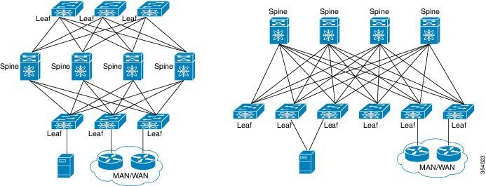
More spine switches provide increased bandwidth and resiliency, and more leaf switches provide more ports and capacity.
Leverages Layer 3 ECMP for unicast or multicast traffic. All links are used for forwarding traffic.
Uniform reachability across the network and deterministic latency. No HSRP is required since each leaf switch has a distributed anycast gateway.
High redundancy is available for node/link failure in the fabric. You can use a vPC setup for redundancy between two leaf or border leaf switches.
Line rate, consistent latency, for all traffic – You will have the same number of hops between any two ToRs.
Flexibility as regards to subscription ratio – You can change the subscription ratio between spine and leaf switches as the fabric scales up or decreases in size.
You can use a two stage or multi stage leaf/spine switch topology for connecting two DC pods.
You can choose the appropriate mix of options for your organization. Some options are given below. They are explained in detail in the next sub section.
FEX in a straight through or dual active mode (eVPC).
Note |
When implementing FEX, ensure that you are aware of the hardware and software dependencies. |
Blade switches.
Hypervisors or bare metal servers attached in vPC mode.
Active-Standby and Active-Active connectivity options.
Connecting to external networks through border spine or border leaf switches.
Services can be attached to service nodes.
Southbound connectivity options are given below. Choose the appropriate option for your setup.

Option 1 —Single threaded links option - In the example, a physical server, UCS FI, and a hypervisor for VMs are connected as single threaded links.
Option 2 —Single threaded link + a local port channel (through an LACP connection) for each link, for physical layer redundancy.
Option 3 —A dual attached physical server and hypervisor in an Active-Standby mode for redundancy.
If the above options are used with FEXs that are attached to the ToR switches, then the topologies are changed, as explained below.

Option 1 —A single attached FEX. This is not recommended.
Option 2 —A single attached FEX scenario with vPC enabled at the leaf switch level. One host attached to the FEX is single attached, another an Active-Standby host, and the third host has an Active-Active connection via a vPC port channel.
Option 3 —This is the same as the second option with one addition. The FEX and the leaf switch devices are connected though a port channel for link redundancy.
Option 4 —A dual attached FEX scenario for FEX and leaf switch redundancy. This option gives more resiliency for the single attached host to reach one of the leaf switches. The second host is dual attached with vPC.
A CLOS based Spine-Leaf architecture is used for the data center fabric in the Programmable Fabric solution. The example displays a folded, 2-stage CLOS Spine-Leaf fabric topology to the left and unfolded representation of the same topology to the right. Note that both the topologies use the same number of devices and links.
The various components and their roles are described below:
IP transport forwarder between Leaf switches (East-West).
Potentially hosting Rendezvous-Point (RP) for the underlay.
Potentially hosting BGP Route-Reflector (RR) for EVPN.
Does not require the VTEP functionality.
Interconnects leaf switches and border leaf switches.
VXLAN edge device to which end hosts are attached. The end hosts include virtual and physical/bare metal servers, FEX devices, 3rd party switches, UCS FI, controllers, and blade switches.
Routes or bridges Classic Ethernet frames and encapsulates them into VXLAN.
Requires the VTEP functionality.
VXLAN edge device.
Routes and bridges Classical Ethernet frames from an outside network and encapsulates them into VXLAN (North-South).
Decapsulates MPLS PE/LISP traffic from an outside network and re-encapsulates it into VXLAN (North-South).
Speaks IGP/EGP routing protocols with the outside network (North-South).
Requires the VTEP functionality.
Interface options are physical routed ports, sub interfaces, and VLAN SVIs over trunk ports.
IPv4/IPv6 route exchange with external neighbors.
IP transport forwarder between Leaf switches (East-West).
Potentially hosting Rendezvous-Point (RP) for the underlay.
Potentially hosting BGP Route-Reflector (RR) for EVPN.
Firewalls.
Load balancers.
Proxy services.
IPS services.
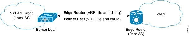
A two box solution comprises of two switches (A Cisco Nexus 5600/7000/7700/9000 Series border leaf switch + a WAN edge switch) to route IP frames from an external network into the VXLAN EVPN fabric.
An one box solution is a single Border PE switch (a Cisco Nexus 7000/7700 Series switch with an F3 line card at the spine or leaf layer) with MPLS PE function. You can connect to external networks through MPLS as well as LISP.

 Feedback