Configure Application Policies

Application Policies Overview

Quality of Service (QoS) refers to the ability of a network to provide preferential or deferential service to selected network traffic. By configuring QoS, you can ensure that network traffic is handled in such a way that makes the most efficient use of network resources while still adhering to the objectives of the business, such as guaranteeing that voice quality meets enterprise standards, or ensuring a high Quality of Experience (QoE) for video.

You can configure QoS in your network using application policies in Cisco DNA Center. Application policies comprise these basic parameters:

  • Application Sets: Sets of applications with similar network traffic needs. Each application set is assigned a business relevance group (business relevant, default, or business irrelevant) that defines the priority of its traffic. QoS parameters in each of the three groups are defined based on Cisco Validated Design (CVD). You can modify some of these parameters to more closely align with your objectives.

  • Site Scope: Sites to which an application policy is applied. If you configure a wired policy, the policy is applied to all the wired devices in the site scope. Likewise, if you configure a wireless policy for a selected service set identifier (SSID), the policy is applied to all of the wireless devices with the SSID defined in the scope.

Cisco DNA Center takes all of these parameters and translates them into the proper device CLI commands. When you deploy the policy, Cisco DNA Center configures these commands on the devices defined in the site scope.


Note


Cisco DNA Center configures QoS policies on devices based on the QoS feature set available on the device. For more information about a device’s QoS implementation, see the corresponding device's product documentation.


CVD-Based Settings in Application Policies

The default QoS trust and queuing settings in application policies are based on the Cisco Validated Design (CVD) for Enterprise Medianet Quality of Service Design. CVDs provide the foundation for systems design based on common use cases or current engineering system priorities. They incorporate a broad set of technologies, features, and applications to address customer needs. Each one has been comprehensively tested and documented by Cisco engineers to ensure faster, more reliable, and fully predictable deployment.

The latest validated designs relating to QoS are published in the Cisco Press book, End-to-End QoS Network Design: Quality of Service for Rich-Media & Cloud Networks, 2nd Edition, available at: http://www.ciscopress.com/store/end-to-end-qos-network-design-quality-of-service-for-9781587143694. For additional information, see the following Cisco documentation:

Site Scope

A site scope defines the sites to which an application policy is applied. When defining a policy, you configure whether a policy is for wired or wireless devices. You also configure a site scope. If you configure a wired policy, the policy is applied to all the wired devices in the site scope. Likewise, if you configure a wireless policy for a selected service set identifier (SSID), the policy is applied to all of the wireless devices in the site scope with the SSID defined in the scope.

This allows you to make tradeoffs as necessary to compensate for differences in the behaviors between wired and wireless network segments. For example, wireless networks typically have lower bandwidth, lower speed, and increased packet loss in comparison to wired networks. Individual wireless segments may exhibit further variation due to local conditions of RF interference, congestion, and other factors, such as the varying capabilities of network devices. The ability to apply per-segment policies to individual wireless segments enables the adjustment of traffic-handling rules to ensure that the highest-priority traffic is least affected by degradation of the wireless network.

Business-Relevance Groups

A business-relevance group classifies a given application set according to how relevant it is to your business and operations.

Business-relevance groups are Business Relevant, Default, and Business Irrelevant, and they essentially map to three types of traffic: high priority, neutral, and low priority.

  • Business Relevant: (High-priority traffic) The applications in this group directly contribute to organizational objectives, and as such, may include a variety of applications, including voice, video, streaming, and collaborative multimedia applications, database applications, enterprise resource applications, email, file transfers, content distribution, and so on. Applications designated as business relevant are treated according to industry best-practice recommendations, as prescribed in Internet Engineering Task Force (IETF) RFC 4594.

  • Default: (Neutral traffic) This group is intended for applications that may or may not be business relevant, for example, generic HTTP or HTTPS traffic may contribute to organizational objectives at times, while at other times, such traffic may not. You may not have insight into the purpose of some applications, for instance, legacy applications or even newly deployed applications. Therefore, the traffic flows for these applications should be treated with the Default Forwarding service, as described in IETF RFC 2747 and 4594.

  • Business Irrelevant: (Low-priority traffic) This group is intended for applications that have been identified as having no contribution towards achieving organizational objectives. They are primarily consumer-oriented or entertainment-oriented or both in nature. We recommend that this type of traffic be treated as a Scavenger service, as described in IETF RFCs 3662 and 4594.

Applications are grouped into application sets and sorted into business-relevance groups. You can include an application set in a policy as-is, or you can modify it to meet the needs of your business objectives and your network configuration.

For example, YouTube is a member of the consumer-media application set, which is business-irrelevant (by default), because most customers typically classify this application this way. However, this classification may not be the true for all companies, for example, some businesses may be using YouTube for training purposes. In such cases, an administrator can move the YouTube application into the streaming-video application set, which is business relevant by default.

Consumers and Producers

You can configure relationships between applications such that when traffic from one application is sent to another application (thus creating a specific a-to-b traffic flow), the traffic is handled in a specific way. The applications in this relationship are called producers and consumers, and are defined as follows:

  • Producer: Sender of the application traffic. For example, in a client/server architecture, the application server is considered the producer because the traffic primarily flows in the server-to-client direction. In the case of a peer-to-peer application, the remote peer is considered the producer.

  • Consumer: Receiver of the application traffic. The consumer may be a client endpoint in a client/server architecture or it may be the local device in a peer-to-peer application. Consumers may be endpoint devices, but may, at times, be specific users of such devices (typically identified by IP addresses or specific subnets). There may also be times when an application is the consumer of another application's traffic flows.

Setting up this relationship allows you to configure specific service levels for traffic that matches this scenario.

Marking, Queuing, and Dropping Treatments

Cisco DNA Center bases its marking, queuing, and dropping treatments on IETF RFC 4594 and the business relevance category that you have assigned to the application. Cisco DNA Center assigns all of the applications in the Default category to the Default Forwarding application class and all of the applications in the Irrelevant Business category to the Scavenger application class. For applications in the Relevant Business category, Cisco DNA Center assigns traffic classes to applications based on the type of application. The following table lists the application classes and their treatments.

Table 1. Marking, Queuing, and Dropping Treatments
Business Relevance Application Class Per-Hop Behavior Queuing and Dropping Application Description

Relevant

VoIP1

Expedited Forwarding (EF)

Priority Queuing (PQ)

VoIP telephony (bearer-only) traffic; for example, Cisco IP phones.

Broadcast Video

Class Selector (CS) 5

PQ

Broadcast TV, live events, video surveillance flows, and similar inelastic streaming media flows; for example, Cisco IP Video Surveillance and Cisco Enterprise TV. (Inelastic flows refer to flows that are highly drop sensitive and have no retransmission or flow-control capabilities or both.)

Real-time Interactive

CS4

PQ

Inelastic high-definition interactive video applications and audio and video components of these applications; for example, Cisco TelePresence.

Multimedia Conferencing

Assured Forwarding (AF) 41

Bandwidth (BW) Queue and Differentiated Services Code Point (DSCP) Weighted Random Early Detect (WRED)

Desktop software multimedia collaboration applications and audio and video components of these applications; for example, Cisco Jabber and Cisco Webex.

Multimedia Streaming

AF31

BW Queue and DSCP WRED

Video-on-Demand (VoD) streaming video flows and desktop virtualization applications, such as Cisco Digital Media System.

Network Control

CS6

BW Queue only2

Network control-plane traffic, which is required for reliable operation of the enterprise network, such as EIGRP, OSPF, BGP, HSRP, IKE, and so on.

Signaling

CS3

BW Queue and DSCP

Control-plane traffic for the IP voice and video telephony infrastructure.

Operations, Administration, and Management (OAM)

CS2

BW Queue and DSCP3

Network operations, administration, and management traffic, such as SSH, SNMP, syslog, and so on.

Transactional Data (Low-Latency Data)

AF21

BW Queue and DSCP WRED

Interactive (foreground) data applications, such as enterprise resource planning (ERP), customer relationship management (CRM), and other database applications.

Bulk Data (High-Throughput Data)

AF11

BW Queue and DSCP WRED

Noninteractive (background) data applications, such as email, file transfer protocol (FTP), and backup applications.

Default

Default Forwarding (Best Effort)

DF

Default Queue and RED

Default applications and applications assigned to the default business-relevant group. Because only a small number of applications are assigned to priority, guaranteed bandwidth, or even to differential service classes, the vast majority of applications continue to default to this best-effort service.

Irrelevant

Scavenger

CS1

Minimum BW Queue (Deferential) and DSCP

Nonbusiness related traffic flows and applications assigned to the business-irrelevant group, such as data or media applications that are entertainment-oriented. Examples include YouTube, Netflix, iTunes, and Xbox Live.

1 VoIP signaling traffic is assigned to the Call Signaling class.
2 WRED is not be enabled on this class because network control traffic should not be dropped.
3 WRED is not enabled on this class because OAM traffic should not be dropped.

Service Provider Profiles

Service provider (SP) profiles define the class of service for a particular WAN provider. You can define 4-class, 5-class, 6-class, and 8-class models.

When application policies are deployed on the devices, each SP profile is assigned a certain service-level agreement (SLA) that maps each SP class to a DSCP value and a percentage of bandwidth allocation.

You can customize the DSCP values and the percentage of bandwidth allocation in a SP profile when configuring an application policy.

After you create the SP profile, you need to configure it on the WAN interfaces.

Table 2. Default SLA Attributes for SP Profiles with 4 Classes

Class Name

DSCP

Priority Class

SLA

Bandwidth (%)

Remaining Bandwidth (%)

Voice

EF

Yes

10

Class 1 Data

AF31

44

Class 2 Data

AF21

25

Default

0

31

Table 3. Default SLA Attributes for SP Profiles with 5 Classes

Class Name

DSCP

Priority Class

SLA

Bandwidth (%)

Remaining Bandwidth (%)

Voice

EF

Yes

10

Class 1 Data

AF31

44

Class 2 Data

AF21

25

Class 3 Data

AF11

1

Default

Best Effort

30

Table 4. Default SLA Attributes for SP Profiles with 6 Classes

Class Name

DSCP

Priority Class

SLA

Bandwidth (%)

Remaining Bandwidth (%)

Class 1 Data

AF31

10

Class 3 Data

AF11

1

Video

AF41

34

Voice

EF

Yes

10

Default

0

30

Class 2 Data

AF21

25

Table 5. Default SLA Attributes for SP Profiles with 8 Classes

Class Name

DSCP

Priority Class

SLA

Bandwidth (%)

Remaining Bandwidth (%)

Network-Control Management

CS6

5

Streaming Video

AF31

10

Call Signalling

CS3

4

Scavenger

CS1

1

Interactive Video

AF41

30

Voice

EF

Yes

10

Default

0

25

Critical Data

AF21

25

Queuing Profiles

Queuing profiles allow you to define an interface's bandwidth allocation based on the interface speed and the traffic class.


Note


Queuing profiles do not apply to WAN-facing interfaces that are connected to a service provider profile.


The following interface speeds are supported:

  • 100 Gbps

  • 10/40 Gbps

  • 1 Gbps

  • 100 Mbps

  • 10 Mbps

  • 1 Mbps

If the speed of an interface falls between two interface speeds, Cisco DNA Center treats the interface at the lower interface speed.


Note


Cisco DNA Center attempts to detect the operational speed of the interface in order to apply the correct policy. However, if a switch port is administratively down, Cisco DNA Center cannot detect the speed. In this case, Cisco DNA Center uses the interface's supported speed.


You define a queuing policy as part of an application policy. When you deploy the application policy, the devices in the sites that are selected in the site scope are configured with the assigned LAN queuing policy. If no LAN queuing policy is assigned, the application policy uses the default CVD queuing policy.

If you change the queuing policy in an application policy that has already been deployed, the policy becomes stale, and you need to redeploy the policy for the changes to be configured on the devices.

Note the following additional guidelines and limitations of queuing policies:

  • You cannot delete a LAN queuing profile if it is used in a policy.

  • If you update a queuing profile that is associated with a policy, the policy is marked as stale. You need to redeploy the policy to provision the latest changes.

  • Traffic class queuing customization does not affect interfaces on Cisco service provider switches and routers. You should continue to configure these interfaces without using Cisco DNA Center.

Table 6. Default CVD LAN Queuing Policy
Traffic Class Default Bandwidth (Total = 100%)4

Business Relevant Voice

10%

Business Relevant Broadcast Video

10%

Business Relevant Real-Time Interactive

13%

Business Relevant Multimedia Conferencing

10%

Business Relevant Multimedia Streaming

10%

Business Relevant Network control

3%

Business Relevant Signaling

2%

Business Relevant OAM

2%

Business Relevant Transactional Data

10%

Business Relevant Bulk Data

4%

Business Relevant Scavenger

1%

Business Relevant Best Effort

25%

4 We recommend that the total bandwidth for Voice, Broadcast Video, and Real-Time Interactive traffic classes equals no more than 33%.

Processing Order for Devices with Limited Resources

Some network devices have a limited memory (called TCAM) for storing network ACLs and access control entries (ACEs). So, because ACLs and ACEs for applications are configured on these devices, the available TCAM space is used. When the TCAM space is depleted, QoS settings for additional applications cannot be configured on that device.

To ensure that QoS policies for the most important applications get configured on these devices, Cisco DNA Center allocates TCAM space in the following order:

  1. Rank: Number assigned to custom and favorite applications, but not to existing, default NBAR applications. The lower the rank number, the higher the priority. For example, an application with rank 1 has a higher priority than an application with rank 2, and so on. Having no rank is the lowest priority.


    Note


    • Custom applications are assigned rank 1 by default.

    • If we mark the NBAR application as favorite, the rank is set to 1000.


  2. Traffic Class: Priority based on the following order: Signaling, Bulk Data, Network Control, Operations Administration Management (Ops Admin Mgmt), Transactional Data, Scavenger, Multimedia Streaming, Multimedia Conferencing, Real Time Interactive, Broadcast Video, and VoIP Telephony.

  3. Popularity: Number (1–10) that is based on CVD criteria. The popularity number cannot be changed. An application with a popularity of 10 has a higher priority than an application with a popularity of 9, and so on.


    Note


    • Custom applications are assigned popularity 0.

    • Default NBAR applications are assigned a popularity number (1–10) that is based on CVD criteria. When you mark an application as a favorite, this does not change the popularity number; only the rank is changed.


  4. Alphabetization: If two or more applications have the same rank and popularity number, they are sorted alphabetically by the application’s name, and assigned a priority accordingly.

For example, let us assume that you define a policy that has the following applications:

  • Custom application, custom_realtime, which has been assigned rank 1 and popularity 10 by default.

  • Custom application, custom_salesforce, which has been assigned rank 1 and popularity 10 by default.

  • Application named corba-iiop, which is in the transactional data traffic class, and you have designated as a favorite, giving that application a ranking of 10,000 and popularity of 9 (based on CVD).

  • Application named gss-http, which is in the Ops Admin Mgmt traffic class, and you have designated as a favorite, giving that application a ranking of 10,000 and popularity of 10 (based on CVD).

  • All other, default NBAR applications, which have no rank, but will be processed according to their traffic class and default popularity (based on CVD).

According to the prioritization rules, the applications are configured on the device in this order:

Application Configuration Order Reason

1. Custom application, custom_realtime

Custom applications are given highest priority. Given that the custom_salesforce and custom_realtime applications have the same rank and popularity, they are sorted alphabetically, custom_realtime before custom_salesforce.

2. Custom application, custom_salesforce

3. Favorite application, gss-http

Because both of these applications have been designated as favorites, they have the same application ranking. So, Cisco DNA Center evaluates them according to their traffic class. Because gss-http is in the Ops Admin Mgmt traffic class, it is processed first, followed by the corba-iiop application, which is in the Transactional Data traffic class. Their popularity does not come into play because the processing order has been determined by their traffic class.

4. Favorite application, corba-iiop

5. All other, default NBAR applications

All other applications are next and are prioritized according to traffic class and then popularity, with the applications having the same popularity being alphabetized according to the application’s name.

Policy Drafts

When you create a policy, you can save it as a draft without having to deploy it. Saving it as a draft allows you to open the policy later and make changes to it. You can also make changes to a deployed policy, and save it as a draft.


Note


After you save or deploy a policy, you cannot change its name.


Draft policies and deployed policies are related to one another, but they have their own versioning.

When you save a policy as a draft, Cisco DNA Center appends the policy name with (Draft), and increments the version number. When you deploy a policy, Cisco DNA Center increments the version number of the deployed policy.

For example, as shown in the following figure, you create a policy named testPolicy1 and save it as a draft. The policy is saved as testPolicy1 (Draft), version number 1. You make a change to the draft and save it again. The policy has the same name, testPolicy1 (Draft), but its version number is incremented to 2.

You decide you like the policy, and you deploy it to the network. The policy is deployed with the name testPolicy1 and its version number is 1. You make a change to the deployed policy and save it as a draft. The draft policy, testPolicy1 (Draft), is incremented to version number 3. When you ultimately deploy that version, testPolicy1 is incremented to version 2.

Figure 1. Deployed Policy and Draft Policy Versioning

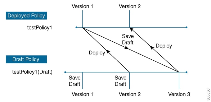
Any time you modify and save either a draft policy or a deployed policy, the draft policy version number is incremented. Similarly, any time you deploy either a draft policy or a modified deployed policy, the deployed policy version is incremented.

Just as with deployed policies, you can display the history of draft policies and roll them back to previous versions.

For more information about viewing the history of policy versions and rolling back to a previous version, see Policy Versioning.

Policy Preview

Before you deploy a policy, you can generate the CLI that will be applied to a device.

The Preview operation generates the CLI commands for a policy, compares them with the CLI commands in the running configuration on the device, and returns only the remaining CLI commands that are required to configure the policy on the device.

After reviewing the preview output, you can deploy the policy to all of the devices in the scope, or you can continue to make changes to the policy.

Policy Precheck

When you create an application policy, you can verify if it will be supported on the devices in the site scope before you deploy it. The precheck function verifies if the device type, model, line cards, and software images support the application policy that you created. If any of these components are not supported, Cisco DNA Center reports a failure for the device. Cisco DNA Center also provides possible ways to correct the failures. If these remedies do not fix the failure, you can remove the device from the site scope.

If you deploy the application policy as-is, the policy will fail to deploy on the devices that reported a failure during the precheck process. To avoid the failure, you can remove the device from the site scope or update the device components to a level that the application policy supports. For a list of supported devices, see the Cisco DNA Center Compatibility Matrix.

Policy Scheduling

After you create or change a policy, you can deploy or redeploy the policy to the devices associated with it. You can deploy or redeploy a policy immediately or at a specific date and time, for example, on a weekend during off-peak hours. You can schedule a policy deployment for wired or wireless devices.

After you have scheduled a policy to be deployed, the policy and site scope are locked. You can view the policy, but you cannot edit it. If you change your mind about deploying the policy, you can cancel it.


Note


When the scheduled event occurs, the policy is validated against the various policy components, for example, applications, application sets, and queuing profiles. If this validation fails, the policy changes are lost.


Policy Versioning

Policy versioning allows you to do the following tasks:

  • Compare a previous version to the current (latest) one to see the differences.

  • Display previous versions of a policy and select a version to reapply to the devices in a site scope.

Editing one version of a policy does not affect other versions of that policy or the components of the policy, such as the application sets that the policy manages. For example, deleting an application set from a policy does not delete the application set from Cisco DNA Center, other versions of that policy, or even other policies. Because policies and application sets exist independent of each other, it is possible to have a policy version that contains application sets that no longer exist. If you attempt to deploy or roll back to an older version of a policy that references an application set that no longer exists, an error occurs.


Note


Policy versioning does not capture changes to applications (such as rank, port, and protocol), application set members, LAN queuing profiles, and sites.


Original Policy Restore

The first time that you deploy a policy to devices, Cisco DNA Center detaches the device's original Cisco Modular QoS CLI policy configurations, but leaves them on the device. Cisco DNA Center stores the device's original NBAR configurations in Cisco DNA Center. This allows you to restore the original Modular QoS CLI policies and NBAR configuration onto the devices later, if needed.


Note


Because the Modular QoS CLI policies are not deleted from the device, if you remove these policies, you will not be able to restore them using the Cisco DNA Center original policy restore feature.


When you restore the original policy configuration onto a device, Cisco DNA Center removes the existing policy configuration that you deployed and reverts to the original configuration that was on the device.

Any Modular QoS CLI policy configurations that existed before you deployed application policies are reattached to the interfaces. However, queuing policies, such as multilayer switching (MLS) configurations, are not restored; instead, the devices retain the MLS configurations that were last applied through Cisco DNA Center.

After you restore the original policy configuration to the device, the policy that is stored in Cisco DNA Center is deleted.

Note the following additional guidelines and limitations for this feature:

  • If the first attempt to deploy a policy to a device fails, Cisco DNA Center automatically attempts to restore the original policy configurations onto the devices.

  • If a device is removed from an application policy after that policy has been applied to the device, the policy remains on the device. Cisco DNA Center does not automatically delete the policy or restore the QoS configuration on the device to its original (pre-Cisco DNA Center) configuration.

Stale Application Policies

An application policy can become stale if you change the configuration of something that is referenced in the policy. If an application policy becomes stale, you need to redeploy it for the changes to take affect.

An application policy can become stale for any of the following reasons:

  • Change to applications referenced in an application set.

  • Change to interfaces, such as SP Profile assignment, WAN subline rate, or WAN or LAN marking.

  • Change to the queuing profile.

  • New site added under a parent site in the policy.

  • Device added to a site that is referenced by the policy.

  • Devices moved between sites in the same policy.

  • Change in interfaces exclusion/inclusion.

  • Change in device Controller-Based Application Recognition (CBAR) status.

Application Policy Guidelines and Limitations

  • Cisco DNA Center cannot learn multiple WLANs with the same SSID name on a wireless controller. At any point, Cisco DNA Center has only one entry for a WLAN with a unique name, although it is possible for the Cisco Wireless Controller to contain multiple entries with the same name and different WLAN profile names.

    You might have duplicate SSID names per wireless controller by design, or you might have inadvertently added a wireless controller with a duplicate SSID name using Cisco DNA Center. In either case, having duplicate SSID names per wireless controller is problematic for several features:

    • Learn Config: Cisco DNA Center learns only one randomly chosen SSID name per wireless controller and discards any remaining duplicate SSID names. (Learn Config is typically used in existing deployment scenario.)

    • Application Policy: When deploying an application policy, Cisco DNA Center randomly applies the policy to only one of the duplicate SSID names and not the others. In addition, policy restore, CLI preview, EasyQoS Fastlane, and PSK override features either fail or have unexpected outcomes.

    • Multiscale Network: In a multiscale network, multiple duplicate SSID names on multiple devices can cause issues. For example, one device has a WLAN configured as a nonfabric SSID, and a second device has the same WLAN, but it is configured as a fabric SSID. When you perform a Learn Config, only one SSID name is learned. The other SSID name from the other device is discarded. This behavior can cause conflicts, especially if the second device supports only fabric SSID names, but Cisco DNA Center is trying to perform operations on the device with nonfabric SSID names.

    • IPACL Policy: When deploying an IPACL policy, Cisco DNA Center randomly applies the policy to only one of the duplicate SSIDs. In addition, scenarios involving Flex Connect are also impacted.

  • Cisco DNA Center does not recommend out-of-band (OOB) changes to device configurations. If you make OOB changes, the policy in Cisco DNA Center and the one configured on the device become inconsistent. The two policies remain inconsistent until you deploy the policy from Cisco DNA Center to the device again.

  • The QoS trust functionality cannot be changed.

  • Custom applications are not supported on the wireless controller. Therefore, custom applications are not selected while creating a wireless application policy.

  • Make sure you delete the corresponding wireless application policy before deleting an SSID from design and reprovisioning the wireless controller.

  • Wireless application for Cisco Catalyst 9800 Series Wireless Controller is not supported on SSID provisioned through learned configuration.

  • Cisco DNA Center provides ACL-based Application Policy support for Cisco Catalyst IE 3300 Rugged Series switches and Cisco Catalyst IE 3400 Heavy Duty Series switches. You can deploy a maximum of eight port-based custom applications. However, there is no restriction for DSCP-based applications.


Note


Cisco DNA Center does not support FlexConnect Local Switching mode for AireOS and Catalyst 9800 Series Wireless Controller platforms.


Manage Application Policies

The following sections provide information about how to manage application policies.

Prerequisites

To configure application policies, you must address the following requirements:

  • Cisco DNA Center supports most Cisco LAN, WAN, and WLAN devices. To verify whether the devices and software versions in your network are supported, see the Cisco DNA Center Compatibility Matrix.

  • Make sure that your Cisco network devices, such as the ISR-G2, ASR 1000, and wireless controller, have the Application Visibility and Control (AVC) feature license installed. For information, see the NBAR2 (Next Generation NBAR) Protocol Pack FAQ.

  • AVC support is available for switches running Cisco IOS-XE 16.9 only if auto-QoS is not configured on the switches. You must upgrade the switches with auto-QOS to Cisco IOS-XE 16.11 or later to get AVC support.

  • For Cisco DNA Center to identify the WAN interfaces that need policies, you must specify the interface type (WAN), and optionally, its subline rate and service-provider Class-of-Service model. For more information, see Assign a Service Provider Profile to a WAN Interface.

  • Verify that the device roles that were assigned to devices during the discovery process are appropriate for your network. If necessary, change the device roles that are not appropriate. For more information, see Change the Device Role (Inventory).

Create an Application Policy

This section provides information about how to create an application policy.

Before you begin

  • Define your business objectives. For example, your business objective might be to improve user productivity by minimizing network response times or to identify and deprioritize nonbusiness applications. Based on these objectives, decide which business relevance category your applications fall into.

  • Make sure that you have devices in your inventory. If not, discover devices using the Discovery feature.

  • Verify that the device roles that were assigned to devices during the discovery process are appropriate for your network. If necessary, change the device roles that are not appropriate. For more information, see Change the Device Role (Inventory).

  • Add devices to sites. For more information, see Add a Device to a Site.

  • If you plan to configure this policy with an SP profile for traffic that is destined for an SP, make sure that you have configured an SP profile. After creating the application policy, you can return to the SP profile and customize its SLA attributes and assign the SP profile to WAN interfaces. For more information, see Configure Service Provider Profiles.

Procedure


Step 1

Click the menu icon () and choose Policy > Application QoS > Application Policies.

Step 2

Click Add Policy.

Step 3

In the Application QoS Policy Name field, enter a name for the policy.

Step 4

Click either the Wired or Wireless radio button.

Step 5

For wireless networks, select an SSID that is provisioned from the SSID drop-down list.

Step 6

Click Site Scope and check the check box next to the sites where you want to deploy the policy.

Note


For policies of wired devices, you cannot select a site that is already assigned to another policy. For policies of wireless devices, you cannot select a site that is already assigned to another policy with the same SSID.

Step 7

For policies of wired devices, you can exclude devices or specific interfaces from being configured with the policy:

  1. From the Site Scope pane, click next to the site you are interested in.

    A list of devices in the selected scope is displayed.

  2. Locate the device that you want to exclude and click the toggle button in the corresponding Policy Exclusions column.

  3. To exclude specific interfaces, click Exclude Interfaces.

  4. From the list of Applicable Interfaces, click the toggle button next to the interfaces that you want to exclude.

    By default, only the Applicable Interfaces are shown. You can choose All from the Show drop-down list to view all the interfaces.

  5. Click < Back to Devices in Site-Name.

  6. Click < Back to Site Scope.

Step 8

For WAN devices, you can configure specific interfaces:

  1. From the Site Scope pane, click next to the desired site.

  2. From the list of devices in the site, click Configure in the SP Profile Settings column next to the desired device.

    Note


    This option is only available for routers.

  3. In the WAN Interface column, from the Select Interface drop-down list, choose an interface.

  4. In the Role column, from the Select Role drop-down list, choose a role according to the type of interface you are configuring:

    • Physical interface: Choose WAN. This role is the only valid role for a physical interface.

    • Tunnel interface: Choose either DMVPN Branch or DMVPN Hub. If you choose DMVPN Hub, you can also define the bandwidth to its corresponding branches.

      Note


      Make sure that the tunnel interfaces have been created on the devices before deploying these policy settings.

  5. In the Service Provider Profile column, from the Select Profile drop-down list, choose an SP profile.

  6. (Optional) If necessary, in the Sub-Line Rate (Mbps) column, enter the upstream bandwidth that the interface requires.

  7. (Optional) To configure additional WAN interfaces, click + and repeat Step c through Step f.

  8. Click Save.

  9. Click < Back to Site Scope.

Step 9

From the Site Scope pane, click OK.

Step 10

(Optional) If the CVD queuing profile (CVD_QUEUING_PROFILE) does not meet your needs, create a custom queuing profile.

  1. Click Queuing Profiles.

  2. Select a queuing profile from the list in the left pane.

  3. Click Select.

Step 11

(Optional) If this policy is for traffic that is destined for an SP, customize the SP profile SLA attributes:

  1. Click SP Profile.

  2. Choose an SP profile.

  3. Customize the SLA attributes (DSCP, SP Bandwidth %, and Queuing Bandwidth %).

Step 12

(Optional) Configure the business relevance of the application sets used in your network.

Cisco DNA Center comes with application sets that are preconfigured into business-relevancy groups. You can keep this configuration or modify it by dragging and dropping an application set from one business-relevancy group to another.

Applications marked as a favorites are listed at the top of the application set. To change favorites, go to the Applications registry.

Step 13

(Optional) Customize applications by creating consumers and assigning them to applications, or by marking an application as bidirectional:

  1. Expand the application group.

  2. Click the gear icon next to the desired application.

  3. From the Traffic Direction area, click the Unidirectional or Bi-directional radio button.

  4. To choose an existing consumer, from the Consumer drop-down list, choose the consumer that you want to configure. To create a new consumer, click + Add Consumer and define the Consumer Name, IP/Subnet, Protocol, and Port/Range.

  5. Click OK.

Step 14

Configure host tracking. Click the Host Tracking toggle button to turn host tracking on or off.

When deploying an application policy, Cisco DNA Center automatically applies ACL entries to the switches to which collaboration endpoints (such as Telepresence units or Cisco phones) are connected.

The ACE matches the voice and video traffic generated by the collaboration endpoint, ensuring that the voice and video traffic are correctly marked.

When host tracking is turned on, Cisco DNA Center tracks the connectivity of the collaboration endpoints within the site scope and to automatically reconfigure the ACL entries when the collaboration endpoints connect to the network or move from one interface to another.

When host tracking is turned off, Cisco DNA Center does not automatically deploy policies to the devices when a collaboration endpoint moves or connects to a new interface. Instead, you need to redeploy the policy for the ACLs to be configured correctly for the collaboration endpoints.

Step 15

(Optional) Preview the CLI commands that will be sent to devices. For more information, see Preview an Application Policy.

Step 16

(Optional) Precheck the devices on which you plan to deploy the policy. For more information, see Precheck an Application Policy.

Step 17

Do one of the following tasks:

  • Save the policy as a draft by clicking Save Draft. For more information, see Policy Drafts.
  • Deploy the policy by clicking Deploy. You can deploy the policy now or schedule it for a later time.

    To deploy the policy now, click the Now radio button and click Apply.

    To schedule the policy deployment for a later date and time, click the Later radio button and define the date and time of the deployment. For more information, see Policy Scheduling.

    Note


    Site time zone setting is not supported for scheduling application policy deployments.


View Application Policy Information

You can display various information about the application policies that you have created and deployed.

Before you begin

You must have at least one deployed application policy.

Procedure


Step 1

Click the menu icon () and choose Policy > Application QoS > Application Policies.

Step 2

Sort the policies by name, or filter them by name, status, or queuing profile.

Step 3

View the list of policies and the following information about each:

  • Policy Name: Name of the policy.

  • Version: Iteration of the policy. Each time a policy is deployed or saved as a draft, it is incremented by one version. For example, when you create a policy and deploy it, the policy is at version 1. If you change the policy and deploy it again, the version of the policy is incremented to version 2. For more information, see Policy Drafts and Policy Versioning.

  • Policy Status: State of the policy. If the policy applied on Cisco Catalyst 3850, Catalyst 4500, and Catalyst 9000 devices and is impacted by the port channel update (create/modify/delete), an alert is shown in the policy status.

  • Deployment Status: State of the last deployment (per device). Presents a summary of the following

    • Devices that were successfully provisioned.

    • Devices that failed to be provisioned.

    • Devices that were not provisioned due to the deployment being terminated.

    Clicking the state of the last deployment displays the Policy Deployment window, which provides a filterable list of devices on which the policy is deployed. For each device, the following information is displayed:

    • Device details (name, site, type, role, and IP address)

    • Success deployment status. Clicking the gear icon next to the status launches the Effective Marking Policy window that shows the Business Relevant and Business Irrelevant applications and the traffic class queue in which they end up. For devices that have limited TCAM resources or an old NBAR protocol pack, only a subset of the applications that are included in the policy can be provisioned, and they are shown in the view.

    • Failure status shows the reason for the failure.

  • Scope: Number of sites (not devices) that are assigned to the policy. For policies of wireless devices, the name of the SSID to which the policy applies is included.

  • LAN Queuing Profile: Name of the LAN queuing profile that is assigned to the policy.


Edit an Application Policy

You can edit an application policy.

Before you begin

You must have created at least one policy.

Procedure


Step 1

Click the menu icon () and choose Policy > Application QoS > Application Policies.

Step 2

Use the Filter field to locate the policy that you want to edit.

Step 3

Click the radio button next to corresponding policy.

Step 4

From the Actions drop-down list, choose Edit.

Step 5

Make changes to the application policy, as needed.

Step 6

You can change the business relevance of an application by moving application set between business relevant, business irrelevant, and default groups.

For information about the application policy settings, see Create an Application Policy.

Step 7

To update the queuing profile, click Queuing Profiles, and select a queuing profile from the list in the left pane.

Step 8

Click Select.

Step 9

Do one of the following tasks:

  • Save the policy as a draft by clicking Save Draft. For more information, see Policy Drafts.
  • Deploy the policy by clicking Deploy. You can deploy the policy now or schedule it for a later time.

    To deploy the policy now, click the Run Now radio button and click Apply.

    To schedule policy deployment for a later date and time, click the Schedule Later radio button and define the date and time of the deployment. For more information, see Policy Scheduling.

    Note


    The site time zone setting is not supported for scheduling application policy deployments.


Save a Draft of an Application Policy

When creating, editing, or cloning a policy, you can save it as a draft so that you can continue to modify it later. You can also make changes to a deployed policy and save it as a draft.

Procedure


Step 1

Click the menu icon () and choose Policy > Application QoS > Application Policies.

Step 2

Create, edit, or clone a policy.

Step 3

Click Save Draft.

For more information, see Policy Drafts.


Deploy an Application Policy

If you make changes that affect a policy's configuration, such as adding a new application or marking an application as a favorite, you must redeploy the policy to implement these changes.


Note


Before deploying a policy, the Auto-QoS configuration is removed automatically from Cisco Catalyst 3650, Catalyst 3850, and Catalyst 9000 devices with Cisco IOS 16.x or later.

After creating custom applications, if CBAR is enabled for a device, the custom applications are configured automatically on the device. You must wait for the synchronization to the latest application registry to complete before deploying the application policy on the device. You can view the synchronization status in Provision > Services > Service Catalog > Application Visibility.

If CBAR is enabled for a device, while deploying the application policy, only the attribute sets and maps are configured on the device, because the custom applications are configured through CBAR.


Procedure


Step 1

Click the menu icon () and choose Policy > Application QoS > Application Policies.

Step 2

Use the Filter field to locate the policy that you want to deploy.

Step 3

Click the radio button next to the policy that you want to deploy.

Step 4

From the Actions drop-down list, choose Deploy.

  1. If you redeploy the policy, you are prompted to take an appropriate action for the devices that were removed from the policy scope. Choose any one of the following actions:

    • Delete policy from the devices (recommended)

    • Remove devices from policy scope

    • Remove devices from policy scope and restore devices to the existing configuration

  2. Click Apply.

Step 5

You are prompted to deploy your policy now, or schedule it for later. Do one of the following:

  • To deploy the policy now, click the Run Now radio button and click Apply.
  • To schedule policy deployment for a later date and time, click the Schedule Later radio button and define the date and time of the deployment.

    Note


    The site time zone setting is not supported for scheduling application policy deployments.


Cancel a Policy Deployment

After you click Deploy, Cisco DNA Center begins to configure the policy on the devices in the site scope. If you realize that you made a mistake, you can cancel the policy deployment.

The policy configuration process is performed as a batch process, in that it configures 40 devices at a time. If you have 40 devices or fewer and you cancel a policy deployment, your devices might be configured anyway, because the deployment to the first batch of devices would have already taken place. However, if you have hundreds of devices, canceling the policy deployment can be useful when needed.

When you click Abort, Cisco DNA Center cancels the configuration process on devices whose configuration has not yet started, and changes the device status to Policy Aborted. Cisco DNA Center does not cancel the deployments that are in the process of being completed or have been completed. These devices retain the updated policy configuration and reflect the state of the policy configuration, whether it is Configuring, Successful, or Failed.

During a policy deployment, click Abort to cancel the policy configuration process.

Delete an Application Policy

You can delete an application policy if it is no longer needed.

Deleting policy deletes class maps, policy map, and association of policy map with wireless policy profile.

Procedure


Step 1

Click the menu icon () and choose Policy > Application QoS > Application Policies.

Step 2

Use the Filter field to locate the policy that you want to delete.

Step 3

Click the radio button next to the policy that you want to delete.

Step 4

From the Actions drop-down list, choose Undeploy Policy.

Step 5

In the Undeploy Policy window, click the Delete policy from devices radio button and click Apply.

Step 6

To confirm the deletion, click OK. Otherwise, click Cancel.

Step 7

When the deletion confirmation message appears, click OK again.

You can view the deletion status of the policies in the Application QoS Policies page. If the status shows deletion failed, do the following:

  1. Click the failed state link under Deployment Status in the Application QoS Policies page.

  2. In the Undeployment Status window, click Retry to delete the policy.


Clone an Application Policy

If an existing application policy has most of the settings that you want in a new policy, you can save time by cloning the existing policy, changing it, and then deploying it to a different scope.

Before you begin

You must have created at least one policy.

Procedure


Step 1

Click the menu icon () and choose Policy > Application QoS > Application Policies.

Step 2

Use the Filter field to locate the policy that you want to clone.

Step 3

Click the radio button next to the policy that you want to clone.

Step 4

From the Actions drop-down list, choose Clone.

Step 5

Configure the application policy, as needed. For information about the application policy settings, see Create an Application Policy.

Step 6

Do one of the following tasks:

  • Save the policy as a draft by clicking Save Draft. For more information, see Policy Drafts.
  • Deploy the policy by clicking Deploy. You can deploy the policy now or schedule it for a later time.

    To deploy the policy now, click the Run Now radio button and click Apply.

    To schedule the policy deployment for a later date and time, click the Schedule Later radio button and define the date and time of the deployment. For more information, see Policy Scheduling.

    Note


    The site time zone setting is not supported for scheduling application policy deployments.


Restore an Application Policy

If you create or make changes to a policy and then decide that you want to start over, you can restore the original QoS configuration that was on the device before you configured it using Cisco DNA Center.

Procedure


Step 1

Click the menu icon () and choose Policy > Application QoS > Application Policies.

Step 2

Use the Filter field to locate the policy that you want to reset.

Step 3

Click the radio button next to the policy.

Step 4

From the Actions drop-down list, choose Undeploy Policy.

Step 5

In the Undeploy Policy window, click the Restore devices to original configurations radio button and click Apply.

Step 6

Click OK to confirm the change or Cancel to cancel it.

You can view the restoration status of the policies in the Application QoS Policies window. If the status shows restoration failed, do the following:

  1. Click the failed state link under Deployment Status in the Application QoS Policies window.

  2. In the Undeployment Status window, click Retry to restore the policy.


Reset the Default CVD Application Policy

The CVD configuration is the default configuration for applications. If you create or make changes to a policy and then decide that you want to start over, you can reset the applications to the CVD configuration. For more information about the CVD configuration, see Application Policies Overview.

Procedure


Step 1

Click the menu icon () and choose Policy > Application QoS > Application Policies.

Step 2

Use the Filter field to locate the policy that you want to reset.

Step 3

Click the radio button next to the policy.

Step 4

From the Actions drop-down list, choose Edit.

Step 5

Click Reset to Cisco Validated Design.

Step 6

Click OK to confirm the change or Cancel to cancel it.

Step 7

Do one of the following tasks:

  • To save a draft of the policy, click Save Draft.
  • To deploy the policy, click Deploy.

Preview an Application Policy

Before you deploy a policy, you can generate the CLI that will be applied to a device and preview the configuration.

Procedure


Step 1

Click the menu icon () and choose Policy > Application QoS > Application Policies.

Step 2

Create or edit a policy, as described in Create an Application Policy or Edit an Application Policy.

Step 3

Before deploying the policy, click Preview.

A list of the devices in the scope appears.

Step 4

Click Generate next to the device that you are interested in.

Cisco DNA Center generates the CLIs for the policy.

Step 5

Click View to view the CLIs or copy them to the clipboard.


Precheck an Application Policy

Before you deploy an application policy, you can check whether the devices in the site scope are supported. The precheck process includes validating a device's model, line cards, and software image.

Procedure


Step 1

Click the menu icon () and choose Policy > Application QoS > Application Policies.

Step 2

Create or edit a policy, as described in Create an Application Policy or Edit an Application Policy.

Step 3

Click Pre-check.

Cisco DNA Center checks the devices and reports failures, if any, in the Pre-Check Result column. The Errors tab shows the devices that do not support this policy. The Warnings tab shows the restrictions or features that are not supported if you chose to deploy this policy in the device. You can still deploy the policy for the devices listed under Warnings tab. To resolve the failures, bring the devices into compliance with the specifications listed in the Cisco DNA Center Compatibility Matrix.


Display Application Policy History

You can display the version history of an application policy. The version history includes the series number (iteration) of the policy and the date and time on which the version was saved.

Procedure


Step 1

Click the menu icon () and choose Policy > Application QoS > Application Policies.

Step 2

Click the radio button next to the policy that interests you.

Step 3

From the Actions drop-down list, choose History.

Step 4

From the Policy History dialog box, you can do the following:

  • To compare a version with the current version, click Difference next to the version that interests you.
  • To roll back to a previous version of the policy, click Rollback next to the version that you want to roll back to.

Roll Back to a Previous Policy Version

If you change a policy configuration, and then realize that it is incorrect, or that is not having the desired affect in your network, you can revert to a policy that is up to five versions back.

Before you begin

You must have created at least two versions of the policy to roll back to a previous policy version.

Procedure


Step 1

Click the menu icon () and choose Policy > Application QoS > Application Policies.

Step 2

Click the radio button next to the policy that interests you.

Step 3

From the Actions drop-down list, choose Show History.

Previous versions of the selected policy are listed in descending order, with the newest version (highest number) at the top of the list and the oldest version (lowest number) at the bottom.

Step 4

(Optional) To view the differences between the selected version and the latest version of a policy, click Difference in the View column.

Step 5

When you determine the policy version that you want to roll back to, click Rollback for that policy version.

Note


If the selected site scope changed between policy versions, rollback is not done on the current (latest) selected site. Only the policy content is rolled back.

Step 6

Click Ok to confirm the rollback procedure.

The rolled back version becomes the newest version.


Manage Queuing Profiles

The following sections provide details about the various tasks that you can perform to manage queuing profiles.

Create a Queuing Profile

Cisco DNA Center provides a default CVD queuing profile (CVD_QUEUING_PROFILE). If this queuing profile does not meet your needs, you can create a custom queuing profile.

Procedure


Step 1

Click the menu icon () and choose Policy > Application QoS > Queuing Profiles.

Step 2

Click Add Profile.

Step 3

In the Profile Name field, enter a name for the profile.

Step 4

Configure the bandwidth for each traffic class by using the slider, clicking the plus (+) or minus (-) sign, or entering a specific number in the field.

The number indicates the percentage of the total interface bandwidth that will be dedicated to the selected application class. Because the total bandwidth equals 100, adding bandwidth to one application class subtracts bandwidth from another application class.

An open lock icon indicates that you can edit the bandwidth for the application class. A closed lock indicates that you cannot edit it.

If you make a mistake, you can return to the CVD settings by clicking Reset to Cisco Validated Design.

The graph in the middle helps you visualize the amount of bandwidth that you are setting for each application class.

Step 5

(For advanced users) To customize the DSCP code points that Cisco DNA Center uses for each of the traffic classes, from the Show drop-down list, choose DSCP Values and configure the value for each application class by entering a specific number in the field.

To customize the DSCP code points required within an SP cloud, configure an SP profile.

Step 6

Click Save.


Edit or Delete a Queuing Profile

Procedure


Step 1

Click the menu icon () and choose Policy > Application QoS > Queuing Profiles.

Step 2

From the Queuing Profile pane, click the radio button next to the queuing profile that you want to edit or delete.

Step 3

Do one of the following tasks:

  • To edit the profile, change the field values, except the profile name, and click Save. For information about the fields, see Create a Queuing Profile.
  • To delete the profile, click Delete.

    You cannot delete a queuing profile if it is referenced in an application policy.


Manage Application Policies for WAN Interfaces

The following sections provide details about the various tasks that you can perform to manage application profiles for WAN interfaces.

Customize Service Provider Profile SLA Attributes

If you do not want to use the default SLA attributes assigned to your SP profile by its class model, you can customize the SP profile SLA attributes to fit your requirements. For more information about the default SP profile SLA Attributes, see Service Provider Profiles.

Before you begin

Make sure that you have devices in your inventory. If not, discover devices using the Discovery feature.

Procedure


Step 1

Click the menu icon () and choose Policy > Application QoS > Application Policies.

Step 2

Use the Filter field to locate the policy that you want to change.

Step 3

Select the radio button next to the policy.

Step 4

From the Actions drop-down list, choose Edit.

Step 5

Click SP Profiles and select an SP profile.

Step 6

You can modify the information in the following fields:

  • DSCP: Differentiated Services Code Point (DSCP) value. Valid values are from 0 to 63.

    • Expedited Forwarding (EF)

    • Class Selector (CS): CS1, CS2, CS3, CS4, CS5, CS6

    • Assured Forwarding: AF11, AF21, AF41

    • Default Forwarding (DF)

    For more information about these DSCP values, see Marking, Queuing, and Dropping Treatments.

  • SP Bandwidth %: Percentage of bandwidth allocated to a specific class of service.

  • Queuing Bandwidth %: Percentage of bandwidth allocated to each of the traffic classes. You can make one of the following changes:

    • To customize the queuing bandwidth, unlock the bandwidth settings by clicking the lock icon and adjust the bandwidth percentages.

    • To calculate the queuing bandwidth automatically from the SP bandwidth, lock the queuing bandwidth settings by clicking the lock icon and then clicking OK to confirm. By default, Cisco DNA Center automatically distributes the queuing bandwidth percentage such that the sum of the queuing bandwidth for all of the traffic classes in an SP class aligns with the SP bandwidth percentage of that class.

Step 7

Click OK.


Assign a Service Provider Profile to a WAN Interface

If you have already created an application policy and now want to assign SP profiles to WAN interfaces, you can edit the policy and perform this configuration, including setting the subline rate on the interface, if needed.

Before you begin

If you have not created a policy, you can create a policy and assign SP profiles to WAN interfaces at the same time. For more information, see Create an Application Policy.

Procedure


Step 1

Click the menu icon () and choose Policy > Application QoS > Application Policies.

Step 2

Use the Filter field to locate the policy that you want to edit.

Step 3

Click the radio button next to the policy.

Step 4

From the Actions drop-down list, choose Edit.

Step 5

From the Site Scope pane, click the gear icon next to the site you are interested in.

Step 6

Click Configure in the SP Profile Settings column for the device you are interested in.

Step 7

In the WAN Interface column, from the Select Interface drop-down list, choose an interface.

Step 8

In the Role column, from the Select Role drop-down list, choose a role according to the type of interface you are configuring:

  • Physical interface: Choose WAN. This role is the only valid role for a physical interface.

  • Tunnel interface: Choose either DMVPN Branch or DMVPN Hub. If you choose DMVPN Hub, you can also define the bandwidth to its corresponding branches.

    Note


    Make sure that the tunnel interfaces have been created on the devices before deploying these policy settings.

Step 9

In the Service Provider Profile column, click the Select Profile drop-down field and choose an SP profile.

Step 10

If necessary, in the Sub-Line Rate (Mbps) column, enter the upstream bandwidth that the interface requires.

Step 11

To configure additional WAN interfaces, click + and repeat Step 7 through Step 10.

Step 12

Click Save.

Step 13

Click < Back to Site Scope.

Step 14

Click OK.

Step 15

Click Deploy.

You are prompted to deploy your policy now or to schedule it for a later time.

Step 16

Do one of the following:

  • To deploy the policy now, click the Run Now radio button and click Apply.
  • To schedule policy deployment for a later date and time, click the Schedule Later radio button and define the date and time of the deployment.

    Note


    The site time zone setting is not supported for scheduling application policy deployments.