Administration

This chapter contains the following topics:

DCNM Server

The DCNM Server menu includes the following submenus:

Starting, Restarting, and Stopping Services

By default, the ICMP connectivity between DCNM and its switches validates the connectivity during Performance Management. If you disable ICMP, Performance Management data will not be fetched from the switches. You can configure this parameter in the server properties. To disable ICMP connectivity check from Cisco DCNM Web UI, choose Administration > DCNM Server > Server Properties, and set skip.checkPingAndManageable parameter value to true.

To clean up the performance manager database (PM DB) stale entries, start, restart, or stop a service, from the Cisco DCNM Web UI, perform the following steps:

Procedure


Step 1

Choose Administration > DCNM Server > Server Status.

The Status window appears that displays the server details.

Step 2

In the Actions column, click the action you want to perform. You can perform the following actions:

  • Start or restart a service.

  • Stop a service.

  • Clean up the stale PM DB entries.

  • Reinitialize the Elasticsearch DB schema.

Step 3

View the status in the Status column.


What to do next

See the latest status in the Status column.

From Cisco DCNM Release 11.4(1), you can see the status of the following services as well:


Note


The following services are available for OVA/ISO deployments only.


  • NTPD server: NTPD service running on DCNM OVA, the IP address, and the port to which the service is bound.

  • DHCP server: DHCP service running on DCNM OVA, the IP address, and the port to which the service is bound.

  • SNMP traps

  • Syslog Receiver

The DCNM servers for these services are as follows:

Service Name

DCNM Server

NTPD Server

0.0.0.0:123

DHCP Server

0.0.0.0:67

SNMP Traps

0.0.0.0:2162

Syslog Server

0.0.0.0:514

Using the Commands Table

The commands table contains links to commands that launch new dialog boxes to provide information about the server status and server administrative utility scripts. You can execute these commands directly on the server CLI.

  • ifconfig: click this link to view information about interface parameters, IP address, and netmask used on the Cisco DCNM server.

  • appmgr status all: click this link to view the DCNM server administrative utility script that checks the status of different services currently running.

  • appmgr show vmware-info: click this link to view information about the CPU and Memory of Virtual Machine.

  • clock: click this link to view information about the server clock details such as time, zone information.


Note


The commands section is applicable only for the OVA or ISO installations.


Customization

From Cisco DCNM Release 11.3(1), you can modify the background image and message on the Web UI login page. This feature helps you to distinguish between the DCNM instances, when you have many instances running at the same time. You can also use a company-branded background on the login page. Click on Restore Defaults to reset the customizations to their original default values.

To remove the customizations and restore to the default values, click Restore defaults.

Login Image

This feature allows you to change the background image on the Cisco DCNM Web UI login page. If you have many instances of DCNM, this will help you identify the correct DCNM instance based on the background image.

To edit the default background image for your Cisco DCNM Web UI login page, perform the following steps:

  1. Choose Administration > DCNM Server > Customization.

  2. In the Login Image area, click Add (+) icon.

    Browse for the image that you need to upload from your local directory. You can choose any of the following format images: JPG, GIF, PNG, and SVG.

  3. Select the image and click Open.

    A status message appears on the right-bottom corner.

    Login image
    Upload Successful 
    

    Note


    We recommend that you upload a scaled image for fast load times.


    The uploaded image is selected and applied as the background image.

  4. To choose an existing image as login image, select the image and wait until you see the message on the right-bottom corner.

  5. To revert to the default login image, click Restore Defaults.

Message of the day (MOTD)

This feature allows you to add a message to the Cisco DCNM Web UI login page. You can a list of messages that will rotate on the configured frequency. This feature allows you to convey important messages to the user on the login page.

To add or edit the message of the day on the Cisco DCNM Web UI login page, perform the following steps:

  1. Choose Administration > DCNM Server > Customization.

  2. In the Message of the day (MOTD) field, enter the message that must appear on the login page.

  3. Click Save.

Default Fabric for Overlay Deployments

From Release 11.4(1), Cisco DCNM Customizations allows you to choose one of the valid Fabrics as default. This feature is available in the Cisco DCNM LAN Fabric deployment only.

To set a default fabric for all overlay deployments on the Cisco DCNM Web UI, perform the following steps:


Note


Only a user with network admin role can use configure the default fabric.
  1. Choose Administration > DCNM Server > Customization.

  2. In the Default Fabric for Overlay Deployments drop-down list, select set a Fabric to set as a default for all the overlay deployments.

  3. Click Save to set the fabric as default.

    A note appears in the right bottom of the window confirming that the default fabric is updated successfully.

  4. To remove the default fabric, choose --select as option from the drop-down list and click Save.

Network Preferences

Earlier to Release 11.5(1), appmgr update network-properties command allows you to modify network properties. From Release 11.5(1), Cisco DCNM allows you to modify few network parameters from the Web UI. Modifying these overwrites the previously configured parameters.

Choose Cisco DCNM Web UI > Admin > DCNM Server > Customization > Network Preferences to modify the DNS, NTP, and the eth1/eth2 interfaces.

DNS

In the DNS field, enter the DNS IP address. You can also configure the DNS server using an IPv6 address. You can configure more than one DNS server. Use comma (,) as differentiator between the IP addresses.


Note


If you’re using Network Insights applications, ensure that the DNS server is valid and reachable.
NTP

In the NTP field, enter the IP address of the NTP server. The value must be an IP or IPv6 address or RFC 1123 compliant name.

Routes
In-Band (eth2)

In the In-Band Network area, enter the IPv4 address and Gateway IPv4 Address for the in-band network. If DCNM is on the IPv6 network, configure the network by entering relevant IPv6 Address for IPv6 address and Gateway IPv6 Address.


Note


When a Nexus Dashboard server is adding a Site from DCNM 11.5(1), it must reach the DCNM server over the Data Network. DCNM Data Network connectivity is defined to be over eth2 interface of the DCNM server; also known as Inband Connectivity interface in DCNM. When the eth2 connectivity of the DCNM with the Data Network Connectivity of the Nexus Dashboard is spanning multiple subnets, that is, when they are Layer3 Route connected, you must add routes in DCNM before adding the Site on ND. Enter the Routes to the ND Data Network over the In-band(eth2) inputs of the dashlet.


The In-Band Network provides reachability to the devices via the front-panel ports.

Out-of-Band (eth1)

In the Out-of-Band Network area, enter the IPv4 address and Gateway IPv4 Address. If DCNM is on the IPv6 network, configure the network by entering relevant IPv6 Address for IPv6 address and Gateway IPv6 Address.

Out-of-band management provides a connection to the device management ports (Typically mgmt0).

Viewing Log Information

You can view the logs for performance manager, SME server, web reports, web server, and web services. These processes have no corresponding GUI that allows you to view information about these log files. If you see errors, preserve these files for viewing.

Beginning with Release 11.2(1), for DCNM OVA and DCNM ISO installations, all log files with .log extension are also listed.


Note


Logs cannot be viewed from a remote server in a federation.


To view the logs from the Cisco DCNM Web UI, perform the following steps:

Procedure


Step 1

Choose Administration > DCNM Server > Logs.

You see a tree-based list of logs in the left column. Under the tree, there is a node for every server in the federation. The log files are under the corresponding server node.

Step 2

Click a log file under each node of the tree to view it on the right.

Step 3

Double-click the tree node for each server to download a ZIP file containing log files from that server.

Step 4

(Optional) Click Generate Techsupport to generate and download files required for technical support.

This file contains more information in addition to log files.

Note


A TAR.GZ file will be downloaded for OVA and ISO deployments, and a ZIP file will be downloaded for all other deployments. You can use the use appmgr tech_support command in the CLI to generate the techsupport file.

Step 5

(Optional) Click the Print icon on the upper right corner to print the logs.


Server Properties

You can set the parameters that are populated as default values in the DCNM server.

The backup configuration files are stored in the following path: /usr/local/cisco/dcm/dcnm/data/archive

The number of archived files that can be retained is set in the # Number of archived files per device to be retained: field. In the Cisco DCNM LAN Fabric installation, the backup is taken per fabric and not per device. If the number of backup files exceeds the value entered in the field, the first version of the backup is deleted to accommodate the latest version. For example, if the value entered in the field is 50 and when the 51st version of the fabric is backed up, the first backup file is deleted.

To set the parameters of the DCNM server from the Cisco DCNM Web UI, perform the following steps:

Procedure


Step 1

Choose Administration > DCNM Server > Server Properties.

Step 2

Click Apply Changes to save the server settings.


Modular Device Support

To support any new hardware that does not require many major changes, a patch can be delivered instead of waiting for the next DCNM release. Modular Device Support helps to deliver and apply the DCNM patch releases. An authorized DCNM administrator can apply the patch to the production setup. Patch releases are applicable for the following scenarios:

  • Support any new hardware, like chassis or line cards

  • Support latest NX-OS versions

  • Support critical fixes as patches

To view the patch details from Cisco DCNM Web UI, perform the following steps:

Procedure


Step 1

Choose Administration > DCNM Server > Modular Device Support.

You see the DCNM Servers column on the left in the window and Modular Device support information window on the right.

Step 2

Expand DCNM Servers to view all the DCNM servers.

It includes the list of patches installed along with the version number, corresponding platforms supported, chassis supported, NX-OS version supported, PID supported, backup directory and the last patch deployment time in the Modular Device support information table.


What to do next

For more details about how to apply and rollback a patch, go to http://www.cisco.com/go/dcnm for more information.

Native HA

Before you begin


Note


Ensure that you clear your browser cache and cookies everytime after a Federation switchover or failover.


Procedure


Step 1

By default, DCNM is bundled with an embedded database engine PostgreSQL. The native DCNM HA is achieved by two DCNMs running as Active / Warm Standby, with their embedded databases synchronized in real time. So once the active DCNM is down, the standby takes over with the same database data and resume the operation. The standby host database down scenario is documented after this procedure.

Step 2

From the menu bar, choose Administration > DCNM Server > Native HA.

You see the Native HA window.

Step 3

You can allow manual failover of DCNM to the standby host by clicking the Failover button, and then click OK.

  • Alternatively, you can initiate this action from the Linux console.
    1. SSH into the DCNM active host.

    2. Enter " " /usr/share/heartbeat/hb_standby”

Step 4

You can allow manual syncing database and disk files to standby host by clicking Force Sync, and then click OK.

Step 5

You can test or validate the HA setup by clicking Test and then click OK.


What to do next

Some HA troubleshooting scenarios are noted in this sub section.

The standby host database is down: Typically, the DCNM database (PostgreSQL) is up on the active and standby hosts. In DCNM 10.1 and earlier versions, the standby database can be down due to a database synchronization failure.

  • Enter “ps -ef | grep post”. You should see multiple postgres processes running. If not, it indicates that the database is down.

  • Restore database data from a backup file that is created at the beginning of database synchronization. Change directory to “/usr/local/cisco/dcm/db”

  • Check existence of file replication/ pgsql-standby-backup.tgz. If the file exists, restore database data files:

    rm -rf    data/* 
    tar -zxf    replication/ pgsql-standby-backup.tgz    data 
    /etc/init.d/postgresql-9.4 start 
    ps -ef | grep post
    

    The active DCNM host will synchronize the two databases.

The TFTP server is not bound to the eth1 VIP address on the active host: The TFTP server should run on the active host (not on the standby host), and it should be bound to the eth1 VIP address. In some setups, the bind address is not the VIP address, as per the TFTP configuration file, and this could cause issues when switches try to use TFTP.

  • Enter “grep bind    /etc/xinetd.d/tftp” to check if the TFTP configuration file has the right bind address. If the displayed IP address is not the eth1 VIP address, then change the bind address to the VIP address. Repeat the procedure for the standby host. Update the bind address to the VIP address.

  • Enter " " /etc/init.d/xinetd restart” on the active host to restart TFTP.


Note


The TFTP server can be started or stopped with the “appmgr start/stop ha-apps” command.


Multi Site Manager

Using Multi Site Manager, you can view the health of a DCNM server application and retrieve switch information for switches in local and remote sites. To access switch information for remote DCNM servers, you must register the server in Multi Site Manager. The procedures to access remote DCNM servers and search for switch information are explained:

Add Remote DCNM Server Information

This procedure allows you to access a DCNM server in a remote site from the DCNM server that you are currently logged on to. For the remote site to access the current DCNM server, registration is required on the remote site.

  1. Choose Administration > DCNM Server > Multi Site Manager. The Multi Site Manager screen comes up.

    The currently logged on DCNM application health status is displayed on the screen.


    Note


    The Application Health function is only available for the DCNM ISO/OVA installation type and not for the Windows/RHEL installation type.


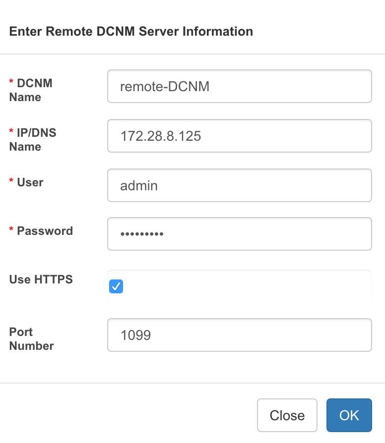
  2. Click +Add DCNM Server. The Enter Remote DCNM Server Information screen comes up.

    Enter the remote DCNM server name, its IP address or URL, the user credentials of the remote DCNM server, and optionally, the port number.


    Note


    Do not disable the Use HTTPS check box. If you disable, DCNM will not be accessible.


  3. Click OK. After validation, the remote DCNM server is represented in the screen, next to the local DCNM server.

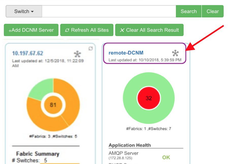
    You can click Refresh All Sites to display updated information.

Retrieve Switch Information

  1. Choose Administration > DCNM Server > Multi Site Manager. The Multi Site Manager screen comes up

  2. From the search box at the top of the screen, search for a switch based on one of the following parameters:

    • VM information (VM IP and VM Name fields) - A connected VM’s IP address or name.

    • Switch information (Switch and MAC fields) – A switch’s name or MAC address.

    • Segment (Segment ID field) that has presence on the switch.

    If there is a match, the switch name appears as a hyperlink below the search box, in the appropriate local or remote DCNM server depiction.

    In this example, the switch leaf3 is available in the remote site managed by a DCNM server. A link to leaf3 is available in the remote-DCNM panel.

  3. Click leaf3 to view detailed switch information in an adjacent browser tab.

    At any point in time, you can click the Launch Topology View icon to view the fabric’s topology.
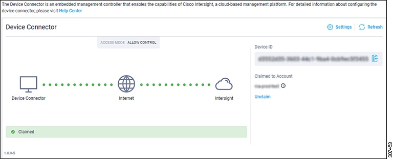
Device Connector

The Device Connector is an embedded management controller that enables the capabilities of Cisco Intersight, a cloud-based management platform.

Networks Insights applications are connected to the Cisco Intersight cloud portal through a Device Connector which is embedded in the management controller of the Cisco DCNM platform. Cisco Intersight is a virtual appliance that helps manage and monitor devices through the Network Insights application. The Device Connector provides a secure way for connected DCNM to send information and receive control instructions from the Cisco Intersight portal, using a secure Internet connection.

Configuring Device Connector

To configure the Device Connector from the Cisco DCNM Web UI, perform the following steps:

  1. Choose Administration > DCNM Server > Device Connector.

    The Device Connector work pane appears.
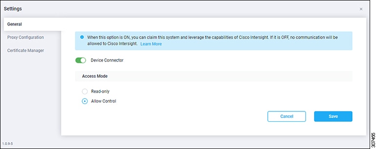
  2. Click Settings.

    The Settings - General window appears.

    • Device Connector (switch)

      This is the main switch for the Device Connector communication with Cisco Intersight. When the switch is on (green highlight), the Device Connector claims the system and leverages the capabilities of the Cisco Intersight. If the switch is off (gray highlight), no communication can occur between Cisco DCNM and Cisco Intersight.

    • Access Mode

      • Read-only: This option ensures that there are no changes to this device from Intersight. For example, actions such as upgrading firmware or a profile deployment is not allowed in the Read-Only mode. However, the actions depend on the features available for a particular system.

      • Allow Control: This option (selected by default) enables you to perform full read/write operations from the appliance, based on the features available in Cisco Intersight.

  3. Set the Device Connector to on (green highlight) and choose Allow Control.

  4. Click Proxy Configuration.

    The Settings - Proxy Configuration window appears.

    • Enable Proxy (switch)

      Enable HTTPS Proxy to configure the proxy settings.


      Note


      Network Insights requires Proxy settings.


    • Proxy Hostname/IP* and Proxy Port*: Enter a proxy hostname or IP address, and a proxy port number.

    • Authentication (switch)

      Enable proxy access through authentication. When the switch is on (green highlight), authentication to the proxy server is required. If the switch is off (gray highlight), it does not require authentication.

      Username* and Password: Enter a user name and password for authentication.

      The device connector does not mandate the format of the login credentials, they are passed as-is to the configured HTTP proxy server. The username must be a qualified domain name depending on the configuration of the HTTP proxy server.

  5. Enable the proxy (green highlight) and enter a hostname and port number.

  6. (Optional) If proxy authentication is required, enable it (green highlight) and enter a username and password.

  7. Click Save.

  8. Click Certificate Manager.

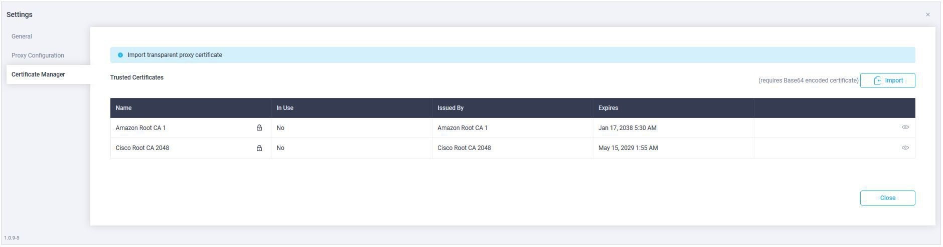
    The trusted certificates appear in the table.

    A list of trusted certificates appears. You can import a valid trusted certificate.

    • Import

      Browse the directory, choose, and import a CA signed certificate.


      Note


      The imported certificate must be in the *.pem (base64encoded) format.


    • You can view the list of certificates with the following information:

      • Name—Common name of the CA certificate.

      • In Use—Whether the certificate in the trust store is used to successfully verify the remote server.

      • Issued By—The issuing authority for the certificate.

      • Expires—The expiry date of the certificate.


        Note


        You cannot delete bundled certificates.


NX-API Certificate Management for Switches

Cisco NX-OS switches require an SSL certificate to function in NX-API HTTPS mode. You can generate the SSL certificates and get it signed by your CA. You can install the certificates manually using CLI commands on switch console.

From Release 11.4(1), Cisco DCNM provides a Web UI framework to upload NX-API certificates to DCNM. Later, you can install the certificates on the switches that are managed by DCNM.

This feature is supported only on Cisco DCNM OVA/ISO deployments.


Note


This feature is supported on switches running on Cisco NXOS version 9.2(3) or higher.


For each switch, the data center administrator generates an ASCII (base64) encoded certificate. This certificate comprises two files:

  • .key file that contains the private key

  • .crt/.cer/.pem file that contains the certificate

Cisco DCNM also supports a single certificate file that contains an embedded key file, that is, .crt/.cer/.pem file can also contain the contents of .key file.

DCNM doesn’t support binary encoded certificates, that is, the certificates with .der extension are not supported. You can protect the key file with a password for encryption. Cisco DCNM does not mandate encryption; however, as this is stored on DCNM, we recommend that you encrypt the key file. DCNM supports AES encryption.

You can either choose CA-signed certificates or self-signed certificates. Cisco DCNM does not mandate the signing; however, the security guidelines suggest you use CA-signed certificates.

You can generate multiple certificates meant for multiple switches, to upload to DCNM. Ensure that you name the certificates appropriately, to help you choose the switch meant for that certificate.

You can upload one certificate and corresponding key file, or bulk upload multiple certificates and key files. After the upload is complete, you can view the upload list before installing these on the switches. If a certificate file that contains an embedded key file is uploaded, DCNM derives the key automatically.

Certificate and the key file must have the same filename. For example, if a certificate filename is mycert.pem, the key filename must be mycert.key. If the certificate and key pair filenames are not the same, then DCNM will not be able to install the certificate on the switch.

Cisco DCNM allows you to bulk install the certificates to the switches. Because bulk installation uses the same password, all encrypted keys must be encrypted with the same password. If the password is different for a key, you cannot install the certificate in bulk mode. Bulk mode installation allows you to install encrypted and unencrypted keys certificates together, but all encrypted keys must have the same password.

When you install a new certificate on the switch, it replaces the existing certificate and replaces it with the new certificate.

You can install the same certificate on multiple switches; however, you cannot use the bulk upload feature.


Note


DCNM doesn’t enforce the validity of certificates or options provided in it. It is up to you and the requirements on the switch to follow the convention. For example, if a certificate is generated for Switch-1 but it is installed on Switch-2, DCNM doesn’t enforce it; switches may choose to accept or reject a certificate based on the parameters in the certificate.


On Cisco DCNM Web UI > Administration > DCNM Server > NX API Certificates, the following tables are displayed:

  • Certificate Installation Status table: Displays the status of certificates last installed on the switches. It also displays the time when the certificates were updated previously.

  • Certificates Uploaded to DCNM table: Displays the certificates uploaded on DCNM and any switch association.

    However, refer to the Certificate Installation Status table to see the certificate and switch association. Upload table is only meant for uploading certificates on DCNM and installing on the switches.

You can also watch the video that demonstrates how to use Switch NX-API SSL Certificate Management feature. See Video: Switch NX-API SSL Certificate Management.

Uploading the certificates on DCNM

To upload the certificates onto DCNM using the Cisco DCNM Web Client UI, perform the following steps:

Procedure

Step 1

Choose Administration > DCNM Server > NX API Certificates.

Step 2

In the Certificates Uploaded to DCNM area, click Upload Certificates to upload the appropriate license file.

Step 3

Browse your local directory and choose the certificate key pair that you must upload to DCNM.

You can choose certificates with extension .cer/.crt/.pem + .key file separately.

Cisco DCNM also allows you to upload a single certificate file that contains an embedded key file. The key file is automatically derived after upload.

Step 4

Click Open to upload the selected files to DCNM.

A successful upload message appears. The uploaded certificates are listed in the Certificates Uploaded to DCNM area.

In the Certificate Installation Status area, the certificate appears, with Status as UPLOADED.

If the certificate is uploaded without the key file, the status shows KEY_MISSING.


Installing Certificates on Switches

To install certificates on the switches using Cisco DCNM Web UI, perform the following steps:

Procedure

Step 1

Choose Administration > DCNM Server > NX API Certificates.

Step 2

In the Certificate Installation Status area, for each certificate, click on the Switch column.

Step 3

From the drop-down list, select the switch to associate with the certificate.

Click Save.

Step 4

Select the certificate that you need to install and click Install Certificates on Switch.

You can select multiple certificates to perform a bulk install.

Step 5

In the Bulk Certificate Install window, upload the certificates to DCNM. Perform the following steps:

You can install a maximum of 20 certificates at the same instance, using the Bulk Install feature.

  1. Choose the file transfer protocol to upload the certificate to DCNM.

    You can choose either SCP or SFTP protocol to upload the certificates.

  2. Check the VRF checkbox for the certificates to support the VRF configuration.

    Enter the VRF name that the switch uses to reach DCNM. Generally, DCNM is reached via management VRF of switches, but it can be any VRF that is configured on the switch that is used to reach DCNM.

  3. In the NX-API Certificate Credentials, enter the password which was used to encrypt the key while generating the certificates.

    Leave this field empty, if the key uploaded along with the certificate is not encrypted.

    Note that you can install unencrypted and encrypted keys and a certificate in a single bulk install; however, you must provide the key password used for encrypted keys.

  4. Click Install.

    A notification message appears to confirm if the certificate was successfully installed on the specific switch.

In the Certificate Installation Status area, the Status of certificate now shows INSTALLED.


Unlinking and Deleting certificates

After the certificates are installed on the switch, DCNM cannot uninstall the certificate from DCNM. However, you can always install a new certificate on the switch. The certificates that are not installed on the switches can be deleted. To delete the certificate installed on the switch, you must unlink the certificate from the switch, and then delete it from DCNM.


Note


Unlinking the certificate from the switch does not delete the certificate on the switch. The certificate still exists on the switch. Cisco DCNM cannot delete the certificate on the Switch.


To delete certificates from DCNM repository, using the Cisco DCNM Web UI, perform the following steps:

Procedure

Step 1

Choose Administration > DCNM Server > NX API Certificates.

Step 2

In the Certificate Installation Status area, select the certificate(s) that you need to delete.

Step 3

Click Clear Certificates.

A confirmation message appears.

Step 4

Click OK to clear the selected certificates.

The status column shows UPLOADED. The Switch column shows NOT_INSTALLED.

Step 5

Select the certificate and click Clear Certificates.

The Certificate is removed from the Certificate Installation Status table.

Step 6

In the Certificates Uploaded to DCNM area, select the certificate that is now unlinked from the Switch.

Click Delete Certificates.

The certificate is deleted from DCNM.


Troubleshooting NX API Certificate Management

While installing a certificate, you can encounter errors. The following sections provide information about troubleshooting the NX-API Certificate Management for switches.

COPY_INSTALL_ERROR

Problem Statement: Error message COPY_INSTALL_ERROR

Reason Cisco DCNM cannot reach the switch.

Solution:

  • Verify if the switch is reachable from Cisco DCNM. You can perform an SSH login and ping the switch to verify.

  • Switch connects to DCNM through it’s management interface. Verify if you can ping DCNM from the Switch console. If the switch requires VRF, very if the correct vrf is provided.

  • If the certificate private key is encrypted, ensure that you provide the correct password.

  • Verify is the correct key file is uploaded with the certificate. Ensure that the certificate file and the key file have the same filename.

CERT_KEY_NOT_FOUND

Problem Statement: Error message CERT_KEY_NOT_FOUND

Reason: Key file was not uploaded while uploading the certificate (.cer, .crt, .pem).

Solution:

  • Ensure that the certificate (.cer, .crt, or .pem) file and its corresponding .key file has the same filename

    For example: If the certificate file name is mycert.crt, the key file must be mycert.key.

  • DCNM identifies key file with certificate file name, and therefore, it is necessary to have the key file with same filename.

  • Upload the certificate and key file with same filename, and install the certificate.

Backing up DCNM

From Cisco DCNM, Release 11.5(1), you can trigger scheduled DCNM backups from the Cisco DCNM Web UI. When you trigger a backup from the Web UI, the appmgr backup command is run. You can see the following information under the Server Backup Jobs tab in the Backup window.

Table 1. Server Backup Jobs Tab

Parameters

Description

Node

Specifies if the backup is active or standby. For standalone nodes, it will appear as a localpath.

Note


For HA cluster, one active node and one standby node is created. However, you can choose only the active node for an HA cluster.

Schedule

Specifies when the scheduled backup is triggered.

Local Path

Specifies the local path, where the backup is stored.

Remote Destination

Specifies the username, host IP, and the remote destination, where the backup is stored. It is empty if you do not save the backup in a remote location.

Note


A copy of the backup is also stored in the local path.

Log Path

Specifies the path where the log entries are stored. You can use this information to troubleshoot any issues.

Saved Backups

Specifies the number of versions of a backup. The default value is 5.

You can perform the following actions in the Backup window:

Creating a Backup

To create a backup from the Cisco DCNM Web UI, perform the following steps:

Procedure

Step 1

Choose Administration > DCNM Server > Backup.

The Backup window appears, which has all the information under the Server Backup Schedules area.

Step 2

Click Add.

The Create Backup Schedule dialog box appears.

Step 3

Choose the time using the Start At drop-down list under the Schedule area.

Step 4

Choose the frequency of the backup.

The valid options are:

  • Daily: Select this radio button if you want to trigger the backup everyday.

  • Weekly: Select this radio button if you want to trigger the backup once a week. If you select this radio button, you get options to choose the day.

Step 5

Enter the number of backups you want to save in the Max # of Saved Backups field under the Destination area.

You can save upto 10 backups and the default value is 5.

Step 6

(Optional) Check the Remote Destination check box to save the backup in a remote location.

The following fields will be available after you check the Remote Destination check box.

Fields

Descriptions

User

Enter the username.

Password

Enter the password.

Note


You don't have to enter the password if you have enabled the key-less configuration between your DCNM and the remote host.

Host IP

Enter the host IP address which is connected to your DCNM.

Path

Enter the remote destination path where you want to save the backup.

Note

 
  • The backup files are huge, with the size in gigabytes.

  • A copy of the backup will always be saved in the local destination as well.

Step 7

Click Create.

The Backup window is populated even when you run the appmgr backup command using the CLI. You can also view the backups, which you scheduled from the Web UI, in the CLI using the appmgr backup schedule show command.


Modifying a Backup

To modify a backup from the Cisco DCNM Web UI, perform the following steps:

Procedure

Step 1

Choose Administration > DCNM Server > Backup.

The Backup window appears, which has all the information under the Server Backup Schedules area.

Step 2

Click Modify.

The Modify Backup Schedule dialog box appears.

Step 3

Make the necessary changes.

Step 4

Click Modify.


Deleting a Backup

To delete a backup from the Cisco DCNM Web UI, perform the following steps:

Procedure

Step 1

Choose Administration > DCNM Server > Backup.

The Backup window appears, which has all the information under the Server Backup Schedules area.

Step 2

Click Delete.

The confirmation dialog box appears.

Step 3

Click Yes.

Note


If you run the appmgr backup schedule none command in the CLI, the backup is deleted. You can verify if the backup is deleted by refreshing the Backup window.


Job Execution Details

You can see the following information under the Job Execution Details tab in the Backup window.

Table 2. Server Backup Schedules Area

Parameters

Description

Node

Specifies if the node is active or standby. For standalone nodes, it will appear as a local node.

Backup File

Specifies the path, where the backup is stored.

Start Time

Specifies the time when the backup process started.

End Time

Specifies the time when the backup process ended.

Log File

Specifies the path where the log entries are stored. You can use this information to troubleshoot any issues.

Status

Specifies if the backup was a success or failed.

Error Message

Specifies error messages, if any, that appeared during the backup.

Manage Licensing

The Manage Licensing menu includes the following submenus:

Managing Licenses

You can view the existing Cisco DCNM licenses by choosing Administration > Manage Licensing > DCNM. You can view and assign licenses in the following tabs:

  • License Assignments

  • Smart License

  • Server License Files


Note


By default, the License Assignments tab appears.

The following table displays the SAN and LAN license information.

Field

Description

License

Specifies SAN or LAN.

Free/Total Server-based Licenses

Specifies the number of free licenses that are purchased out of the total number of licenses. The total number of licenses for new installations are 50. However, the total number of licenses continues to be 500 for inline upgrade.

Unlicensed/Total (Switches/VDCs)

Specifies the number of unlicensed switches or VDCs out of the total number of switches or VDCs.

Need to Purchase

Specifies the number of licenses to be purchased.

This section includes the following topics:

License Assignments

The following table displays the license assignment details for every switch or VDC.

Field

Description

Group

Displays if the group is fabric or LAN.

Switch Name

Displays the name of the switch.

WWN/Chassis ID

Displays the world wide name or Chassis ID.

Model

Displays the model of the device. For example, DS-C9124 or N5K-C5020P-BF.

License State

Displays the license state of the switch that can be one of the following:

  • Permanent

  • Eval

  • Unlicensed

  • Not Applicable

  • Expired

  • Invalid

  • Smart

License Type

Displays the license type of the switch that can be one of the following:

  • DCNM-Server

  • Switch

  • Smart

  • Honor

  • Switch-Smart

Expiration Date

Displays the expiry date of the license.

Note

 
Text under the Expiration Date column is in red for licenses, which expire in seven days.

Assign License

Select a row and click this option on the toolbar to assign the license.

Unassign License

Select a row and click this option on the toolbar to unassign the license.

Assign All

Click this option on the toolbar to refresh the table and assign the licenses for all the items in the table.

Unassign All

Click this option on the toolbar to refresh the table and unassign all the licenses.


Note


You must have network administrator privileges to assign or unassign licenses.


When the fabric is first discovered and if the switch does not have a valid switch-based license, a license is automatically assigned to the fabric from the file license pool until no more licenses are left in the pool. If you have an existing fabric and a new switch is added to the fabric, the new switch is assigned a license if one is available in the file license pool and if it does not already have a switch-based license.

After you register smart license, if you click Assign License for a switch that does not have a permanent license, a smart license is assigned to the switch. The priority of licenses that are assigned are in the following order:

  1. Permanent

  2. Smart

  3. Eval

To assign license to switches through POAP, refer to DCNM Licensing Guide.

Disabling smart licensing unassigns licenses of switches that were smart-licensed.

The evaluation license is assigned for switches that do not support smart licensing. The license state is Eval and the license type is DCNM-Server. See Cisco DCNM Licensing Guide, Release 11.x to view the list of switches that support smart licensing.

Honor License Mode

From Release 11.3(1), Cisco DCNM Eval license validity is extended from 30 days to 60 days. That implies, after 60 days. Every license has an expiry date attached to it. After the license expires, Cisco DCNM allows you to use all the licensed features. Switches remain in honor mode until the switch is licensed again or the user manually removes the license.

If there are switches in the Honor License mode, an error message appears after you logon to DCNM.

***************************************
*Your licenses are out of compliance.
Your inventory contains switches that are unlicensed for DCNM Operation*

***************************************

Go to Administration > Manage Licensing > DCNM, In the Switches/VDCs table, select the switch and click Assign License to renew the license.

Guidelines
  • Switches that don’t have a license assigned to them is considered unlicensed. Unlicensed Switches aren’t allowed to use Licensed DCNM features.

  • If a switch has an expired EVAL license, it will change from EVAL to Honor mode and the license features continues to be operational.

  • You can’t assign expired EVAL licenses to the switches.

  • Switches with switch-based honor license can’t be overwritten with any server-based license.

  • When a license is assigned to a discovered switch and a valid license isn’t available, then an honor-based license with expiration date will be assigned to the switch.

Nag events for Honor-mode licenses

For every license in honor mode, an event is generated every seven days. A nag event informs the user "DCNM-SAN file license is in honor mode, need to assign/purchase a new license for this switch." Or "DCNM-LAN file license is in honor mode, need to assign/purchase a new license for this switch."

Additional popup notification appears when you logon to Cisco DCNM, to inform that “DCNM‐SAN file license is in honor mode, need to assign/purchase a new license for this switch.”

Server-based honor license support

On the DCNM Web UI > Administration > Manage Licensing > DCNM, the Licensed State column displays Honor and Expiration Date column displays the date, time, and when the license expired and changed to the Honor mode.

Switches will remain in honor mode after reboot also. To change the license from honor mode, you must manually unassign the license or assign a new valid license to the switch.

The following image shows license page with a SAN switch in Honor mode.

The following image shows license page with a LAN switch in Honor mode.

The following image shows the switch table displaying the honor mode of license and term.

The following image shows Switch Dashboard with a LAN switch in Honor mode license.

The following image shows Switch Dashboard with a SAN switch in Honor mode license.

The following image shows the SAN Client License Agreement tab.

The following image shows the SAN Client License files tab.


Note


Switch-based honor licenses can’t be overwritten with server-based license files.


Smart License

From Cisco DCNM Release 11.1(1), you can use the smart licensing feature to manage licenses at device-level and renew them if required. From Cisco DCNM Web UI, choose Administration > Manage Licensing > DCNM > Smart License. You will see a brief introduction on Cisco smart licensing, a menu bar, and the Switch Licenses area.

Introduction to Smart Licensing

Cisco Smart Licensing is a flexible licensing model that provides you with an easier, faster, and more consistent way to purchase and manage software across the Cisco portfolio and across your organization. And it’s secure – you control what users can access. With Smart Licensing you get:

  • Easy Activation: Smart Licensing establishes a pool of software licenses that can be used across the entire organization—no more PAKs (Product Activation Keys).

  • Unified Management: My Cisco Entitlements (MCE) provides a complete view into all of your Cisco products and services in an easy-to-use portal, so you always know what you have and what you are using.

  • License Flexibility: Your software is not node-locked to your hardware, so you can easily use and transfer licenses as needed.

To use Smart Licensing, you must first set up a Smart Account on Cisco Software Central (https://software.cisco.com/software/csws/ws/platform/home).

For a more detailed overview on Cisco Licensing, go to https://www.cisco.com/c/en/us/buy/licensing/licensing-guide.html.

In the introduction, click Click Here to view the information on smart software licensing.

The menu bar has the following icons:

  • Registration Status: Displays details of the current registration in a pop-up window when clicked. The value is UNCONFIGURED if the smart licensing is not enabled. After you enable the smart licensing without registering, the value is set to DEREGISTERED. The value is set to REGISTERED after you register. Click the registration status to view the last action, account details, and other registration details in the Registration Details pop-up window.

  • License Status: Specifies the status of the license. The value is UNCONFIGURED if the smart licensing is not enabled. After you enable the smart licensing without registering, the value is set to NO LICENSES IN USE. The value is set to AUTHORIZED or OUT-OF-COMPLIANCE after registering and assigning licenses. Click the license status to view the last action, last authorization attempt, next authorization attempt, and the authorization expiry in the License Authorization Details pop-up window.

  • Control: Allows you to enable or disable smart licensing, register tokens, and renew the authorization.

The following table describes the fields that appear in the Switch Licenses section.

Field

Description

Name

Specifies the license name.

Count

Specifies the number of licenses used.

Status

Specifies the status of the licenses used. Valid values are Authorized and Out of Compliance.

Description

Specifies the type and details of the license.

Last Updated

Specifies the timestamp when switch licenses were last updated.

Print

Allows you to print the details of switch licenses.

Export

Allows you to export the license details.

After you remove a product license from your account in Cisco Smart Software Manager, disable the smart licensing and register it again.

Enabling Smart Licensing
To enable smart licensing from Cisco DCNM Web UI, perform the following steps:
Procedure

Step 1

Choose Administration > Manage Licensing > DCNM > Smart License.

Step 2

Click Control and choose Enable in the drop-down list to enable the smart licensing.

A confirmation window appears.

Step 3

Click Yes.

Instructions to register the DCNM instance appear.

The registration status changes from UNCONFIGURED to DEREGISTERED, and the license status changes from UNCONFIGURED to No Licenses in Use.


Registering a Cisco DCNM Instance
Before you begin
Create a token in Cisco Smart Software Manager.
Procedure

Step 1

Choose Administration > Manage Licensing > DCNM > Smart License.

Step 2

Click Control and choose Register in the drop-down list.

The Register window appears.

Step 3

Select the transport option to register the smart licensing agent.

The options are:

  • Default - DCNM communicates directly with Cisco’s licensing servers

    This option uses the following URL: https://tools.cisco.com/its/service/oddce/services/DDCEService

  • Transport Gateway - Proxy via Gateway or Satellite

    Enter the URL if you select this option.

  • Proxy - Proxy via intermediate HTTP or HTTPS proxy

    Enter the URL and the port if you select this option.

Step 4

Enter the registration token in the Token field.

Step 5

Click Submit to register the license.

The registration status changes from DEREGISTERED to REGISTERED. The name, count, and status of switch licenses appear.

Click Registration Status: REGISTERED to see the details of the registered token.

The switch details are updated under the Switches/VDCs section of the License Assignments tab. The license type and the license state of switches that are licensed using the smart license option are Smart.


What to do next

Troubleshoot communication errors, if any, that you encounter after the registration.

Troubleshooting Communication Errors

To resolve the communication errors during registration, perform the following steps:

Procedure

Step 1

Stop the DCNM service.

Step 2

Open the server properties file from the following path: /usr/local/cisco/dcm/fm/conf/server.properties

Note


The server properties file for Windows will be in the following location: C:/Program Files/Cisco/dcm/fm/conf/server.properties

Step 3

Include the following property in the server properties file: #cisco.smart.license.production=false #smartlicense.url.transport=https://CiscoSatellite_Server_IP/Transportgateway/services/DeviceRequestHandler

Step 4

Update the Cisco satellite details in Host Database in the /etc/hosts file in the following syntax: Satellite_Server_IP CiscoSatellite

Step 5

Start the DCNM service.


Renew Authorization

You can manually renew the authorization only if you have registered. Automatic reauthorization happens periodically. Click License Status to view details about the next automatic reauthorization. To renew authorization from Cisco DCNM Web UI, perform the following steps:

Procedure

Step 1

Choose Administration > Manage Licensing > DCNM > Smart License.

Step 2

Click Control and choose Renew Authorization in the drop-down list to renew any licensing authorizations.

A request is sent to Cisco Smart Software Manager to fetch updates, if any. The Smart Licenses window is refreshed after the update.


Disabling Smart Licensing
To disable smart licensing from Cisco DCNM Web UI, perform the following steps:
Procedure

Step 1

Choose Administration > Manage Licensing > DCNM > Smart License.

Step 2

Select Control and select Disable to disable smart licensing.

A confirmation window appears.

Step 3

Click Yes.

The license status of the switches using this token, under the License Assignments tab, changes to Unlicensed. This token is removed from the list under the Product Instances tab in the Cisco Smart Software Manager.

If a smart license is not available and you disable smart licensing, release the license manually from the License Assignments tab.


Switch Smart License

If the switch is pre-configured with a smart license, DCNM validates and assigns a switch smart license. To assign licenses to switch using the Cisco DCNM UI, choose Administration > Manage Licensing >Assign License or, AssignAll.


Note


For switches in managed mode, switch smart license must be assigned through DCNM.


Note


From Cisco NX-OS Release 9.3(6), switch smart license is supported.


To enable switch smart license on DCNM:

  • Enable smart license feature on the switch, using freeform CLI configuration.

  • Configure smart licensing on the switch, using feature license smart or license smart enable command on the switch.

  • Push token of your device to smart account using license smart register idtoken command. Use EXEC option in DCNM to push token. For more details, refer to Running EXEC Mode Commands in DCNM.

For unlicensed switches, licenses are assigned based on this priority:

  1. DCNM Smart License

  2. DCNM Server License

  3. DCNM Eval License

Server License Files

From Cisco DCNM Web UI, choose Administration > Manage Licensing > DCNM > Server License Files. The following table displays the Cisco DCNM server license fields.

Field

Description

Filename

Specifies the license file name.

Feature

Specifies the licensed feature.

PID

Specifies the product ID.

LAN (Free/Total)

Displays the number of free versus total licenses for LAN.

Expiration Date

Displays the expiry date of the license.

Note

 
Text in the Expiration Date field is in Red for licenses that expires in seven days.
Adding Cisco DCNM Licenses

To add Cisco DCNM licenses from Cisco DCNM, perform the following steps:

Before you begin
You must have network administrator privileges to complete the following procedure.
Procedure

Step 1

Choose Administration > Manage Licensing > DCNM to start the license wizard.

Step 2

Choose the Server License Files tab.

The valid Cisco DCNM-LAN license files are displayed.

Ensure that the security agent is disabled when you load licenses.

Step 3

Download the license pack file that you received from Cisco into a directory on the local system.

Step 4

Click Add License File and select the license pack file that you saved on the local machine.

The file is uploaded to the server machine, which is saved into the server license directory, and then loaded on to the server.

Note

 
Ensure that you do not edit the contents of the .lic file or the Cisco DCNM software ignores any features that are associated with that license file. The contents of the file are signed and must remain intact. When you accidentally copy, rename, or insert the license file multiple times, the duplicate files are ignored, but the original is counted.

Switch Features—Bulk Install

From Release 11.3(1), Cisco DCNM allows you to upload multiple licenses at a single instance. DCNM parses the license files and extract the switch serial numbers. It maps the serial numbers in the license files with the discovered fabric to install the licenses on each switch. License files are moved to bootflash and installed.

To bulk install licenses to the switches on the Cisco DCNM Web Client UI, perform the following steps:

  1. Choose Administration > Manage Licensing > Switch features.

  2. In the Switch Licenses area, click Upload License files to upload the appropriate license file.

    The Bulk Switch License Install window appears.

  3. In the Select file, click Select License file(s).

    Navigate and choose the appropriate license file located in your local directory.

    Click Open.

  4. Choose the file transfer protocol to copy the license file from the DCNM server to the switch.

    • Choose either TFTP, SCP, or SFTP protocol to upload the license file.


      Note


      Not all protocols are supported for all platforms. TFTP is supported for Win/RHEL DCNM SAN installation only. However, SFTP/SCP supported for all installation types.


  5. Check the VRF check box for the licenses to support VRF configuration.

    Enter the VRF name of one of their defined routes.

  6. Check the Overwrite file on Switch checkbox, to overwrite the license file with the new uploaded license file.


    Note


    The overwrite command copies the new file over the existing one in boot flash. If the previous license was already installed, it won’t override the installation.


  7. In the DCNM Server credentials, enter the root username and password for the DCNM server.

    Enter the authentication credentials for access to DCNM. For DCNM Linux deployment, this is the username. For OVA\ISO deployments, use the credentials of the sysadmin user.

  8. Click Upload.

    The License file is uploaded to the DCNM. The following information is extracted from the license file.

    • Switch IP – IP Address of the switch to which this license is assigned.

    • License File – filename of the license file

    • Features List –list of features supported by the license file

  9. Select the set of licenses that you want to upload and install on their respective switches. A license file is applicable for a single specific switch.

  10. Click Install Licenses.

    The selected licenses are uploaded and installed on their respective switches. Status messages, including any issues or errors are updated for each file as it completes.

  11. After the license matches with respective devices and installs, the License Status table displays the status.

Switch-based honor license support

On the DCNM Web UI > Inventory > Switch > License, the Type column displays “Unlicensed Honor License” and Warnings column displays Honor started: … with elapsed time since the license was changed to the Honor mode.


Note


Switch-based honor licenses can’t be overwritten with server-based license files.


Application Licenses

From Release 11.3(1), you can manage licenses for applications on the Cisco DCNM. Choose Web UI > Administration > Manage Licensing > Applications to view the Application Licenses.

The Application Licenses tab displays the DCNM Applications with a summary of their unlicensed/total switches and if they are out of compliance. The PID Per Application Usage table displays the actual counts per PID given to the server from the Application Framework. The PIDs that need to be purchased for each application is also listed.

The Application License Files tab allows you to add license files for the applications. Click on Add license file to add license file from your local directory. The license filename, application name, PID, device count and expiration date details are extracted from the imported license file. If the license isn’t permanent or is eval or term, the expiration date is also listed.

The following image shows a sample error message while uploading an application license file.

Management Users


Note


Every time you login to DCNM, the DCNM server fetches information from the ISE server for AAA authentication. The ISE server will not authenticate again, after the first login.


The Management Users menu includes the following submenus:

Remote AAA

To configure remote AAA from the Cisco DCNM Web UI, perform the following steps:

Procedure


Step 1

Choose Administration > Management Users > Remote AAA Properties.

The AAA properties configuration window appears.

Step 2

Use the radio button to select one of the following authentication modes:

  • Local: In this mode the authentication authenticates with the local server.

  • Radius: In this mode the authentication authenticates against the RADIUS servers specified.

  • TACACS+: In this mode the authentication authenticates against the TACACS servers specified.

  • Switch: In this mode the authentication authenticates against the switches specified.

  • LDAP: In this mode the authentication authenticates against the LDAP server specified.

Step 3

Click Apply.


Local

Procedure

Step 1

Use the radio button and select Local as the authentication mode.

Step 2

Click Apply to confirm the authentication mode.


Radius

Procedure

Step 1

Use the radio button and select Radius as the authentication mode.

Note


When using the DCNM AAA or Radius authentication, you should not specify the hash (#) symbol at the beginning of a secret key. Otherwise, DCNM will try to use # as encrypted, and it will fail.

Step 2

Specify the Primary server details and click Test to test the server.

Step 3

(Optional) Specify the Secondary and Tertiary server details and click Test to test the server.

Step 4

Click Apply to confirm the authentication mode.


TACACS+

Procedure

Step 1

Use the radio button and select TACACS+ as the authentication mode.

Note


When using the DCNM AAA or Radius authentication, you should not specify the hash (#) symbol at the beginning of a secret key. Otherwise, DCNM will try to use # as encrypted, and it will fail.

Step 2

Specify the Primary server details and click Test to test the server.

Step 3

(Optional) Specify the Secondary and Tertiary server details and click Test to test the server.

Note


For IPv6 transport, enter Physical and VIP address for AAA authentication as the order of addresses changes during failover situation.

Step 4

Click Apply to confirm the authentication mode.


Switch

Procedure

Step 1

Use the radio button to select Switch as the authentication mode.

DCNM also supports LAN switches with the IPv6 management interface.

Step 2

Specify the Primary Switch name and click Apply to confirm the authentication mode.

Step 3

(Optional) Specify the names for Secondary and Tertiary Switches.

Step 4

Click Apply to confirm the authentication mode.


LDAP

Procedure

Step 1

Use the radio button and select LDAP as the authentication mode.

Authentication mode - LDAP

Step 2

In the Host field, enter either the IPv4 or IPv6 address.

If DNS service is enabled, you can enter DNS address (hostname) of the LDAP server.

Step 3

In the Port field, enter a port number.

Enter 389 for non-SSL; enter 636 for SSL. By default, the port is configured for non-SSL.

Step 4

Select the SSL Enabled check box, if SSL is enabled on the AAA server.

Note


You must enter 636 in the Port field, and select SSL Enabled check box to use LDAP over SSL.

This ensures the integrity and confidentiality of the transferred data by causing the LDAP client to establish a SSL session, before sending the bind or search request.

Note


Cisco DCNM establishes a secured connection with the LDAP server using TLS. Cisco DCNM supports all versions of TLS. However, the specific version of TLS is determined by the LDAP server.

For example, if the LDAP server supports TLSv1.2 by default, DCNM will connect using TLSv1.2.

Step 5

In the Base DN field, enter the base domain name.

The LDAP server searches this domain. You can find the base DN by using the dsquery.exe user -name <display_name> command on the LDAP server.

For example:

ldapserver# dsquery.exe users -name "John Smith"

CN=john smith,CN=Users,DC=cisco,DC=com

The Base DN is DC=cisco,DC=com.

Note


Ensure that you enter the elements within the Base DN in the correct order. This specifies the navigation of the application when querying Active Directory.

Step 6

In the Filter field, specify the filter parameters.

These values are used to send a search query to the Active Directory. The LDAP search filter string is limited to a maximum of 128 characters.

For example:

  • $userid@cisco.com

    This matches the user principal name.

  • CN=$userid,OU=Employees,OU=Cisco Users

    This matches the exact user DN.

Step 7

Choose an option to determine a role. Select either Attribute or Admin Group Map.

  • Admin Group Map: In this mode, DCNM queries LDAP server for a user based on the Base DN and filter. If the user is a part of any user group, the DCNM role will be mapped to that user group.

  • Attribute: In this mode, DCNM queries for a user attribute. You can select any attribute. When you choose Attribute, the Role Admin Group field changes to Role Attributes.

Step 8

Enter value for either Roles Attributes or Role Admin Group field, based on the selection in the previous step.

  • If you chose Admin Group Map, enter the name of the admin group in the Role Admin Group field.

  • If you chose Attribute, enter the appropriate attribute in the Attributes field.

Step 9

In the Map to DCNM Role field, enter the name of the DCNM role that will be mapped to the user.

Generally, network-admin or network-operator are the most typical roles.

For example:

Role Admin Group: dcnm-admins
Map to DCNM Role: network-admin

This example maps the Active Directory User Group dcnm-admins to the network-admin role.

To map multiple Active Directory User Groups to multiple roles, use the following format:

Role Admin Group:
Map To DCNM Role: dcnm-admins:network-admin;dcnm-operators:network-operator

Note that Role Admin Group is blank, and Map To DCNM Role contains two entries delimited by a semicolon.

Step 10

In the Access Map field, enter the Role Based Access Control (RBAC) device group to be mapped to the user.

Step 11

Click Test to verify the configuration. The Test AAA Server window appears.

Step 12

Enter a valid Username and Password in the Test AAA Server window.

If the configuration is correct, the following message is displayed.

Authentication succeeded.
The cisco-av-pair should return 'role=network-admin' if this user needs to 
see the DCNM Admin pages. 'SME' roles will allow SME page access. All other 
roles - even if defined on the switches - will be treated 
as network operator.

This message is displayed regardless of 'Role Admin Group' or 'Attribute' mode. It implies that Cisco DCNM can query your Active Directory, the groups, and the roles are configured correctly.

If the test fails, the LDAP Authentication Failed message is displayed.

Warning


Don’t save the configuration unless the test is successful. You cannot access DCNM if you save incorrect configurations.

Step 13

Click Apply Changes icon (located in the right top corner of the screen) to save the configuration.

Step 14

Restart the DCNM SAN service.

  • For Windows – On your system navigate to Computer Management > Services and Applications > Services. Locate and right click on the DCNM application. Select Stop. After a minute, right click on the DCNM application and select Start to restart the DCNM SAN service.

  • For Linux – Go to /etc/init.d/FMServer.restart and hit return key to restart DCNM SAN service.


Managing Local Users

As an admin user, you can use Cisco DCNM Web UI to create a new user, assign the role and associate one or more groups or scope for the user.

From DCNM release 11.5(1), new user role device-upg-admin is added to perform operations only in Image Management window.

This section contains the following:

Adding Local Users

Procedure

Step 1

From the menu bar, choose Administration > Management Users > Local. You see the Local Users page.

Step 2

Click Add User.

You see the Add User dialog box.

Step 3

Enter the username in the User name field.

Note

 
The username is case sensitive, but the username guest is a reserved name, which is not case sensitive. The guest user can only view reports. The guest user cannot change the guest password, or access the Admin options in DCNM Web Client.

Step 4

From the Role drop-down list, select a role for the user.

Step 5

In the Password field, enter the password.

Note


All special characters, except SPACE is allowed in the password.

Step 6

In the Confirm Password field, enter the password again.

Step 7

Click Add to add the user to the database.

Step 8

Repeat Steps 2 through 7 to continue adding users.


Deleting Local Users

To delete local users from the Cisco DCNM Web UI, perform the following steps:
Procedure

Step 1

Choose Administration > Management Users > Local.

The Local Users page is displayed.

Step 2

Select one or more users from the Local Users table and click the Delete User button.

Step 3

Click Yes on the warning window to delete the local user. Click No to cancel deletion.


Editing a User

To edit a user from the Cisco DCNM Web UI, perform the following steps:
Procedure

Step 1

Choose Administration > Management Users > Local.

Step 2

Use the checkbox to select a user and click the Edit User icon.

Step 3

In the Edit User window, the Username and Role are mentioned by default. Specify the Password and Confirm Password.

Step 4

Click Apply to save the changes.


User Access

You can select specific groups or fabrics that local users can access. This restricts local users from accessing specific groups or fabrics for which they have not been provided access. To do this, perform the following steps:

Procedure

Step 1

Choose Administration > Management Users > Local.

The Local Users window is displayed.

Step 2

Select one user from the Local Users table. Click User Access.

The User Access selection window is displayed.

Step 3

Select the specific groups or fabrics that the user can access and click Apply.

Note


The User Access button grays out and the value under the Access column isn’t Data Center if the user with the network-admin role doesn’t have access to the entire data center. In that case, to create a new network-admin role user with access to the entire data center use the addUser.sh/bat script.


Managing Clients

You can use Cisco DCNM to disconnect DCNM Client Servers.

Procedure


Step 1

Choose Administration > Management Users > Clients.

A list of DCNM Servers are displayed.

Step 2

Use the check box to select a DCNM server and click Disconnect Client to disconnect the DCNM server.

Note

 
You cannot disconnect a current client session.

Performance Setup

The Performance Setup menu includes the following submenus:

Performance Setup LAN Collections

If you are managing your switches with the Performance Manager, you must set up an initial set of flows and collections on the switch. You can use Cisco DCNM to add and remove performance collections. License the switch and kept it in the Managed Continuously state before creating a collection for the switch.


Note


  • To collect Performance Manager data, ICMP ping must be enabled between the switch and DCNM server. Set pm.skip.checkPingAndManageable server property to true and then restart the DCNM. Choose Web UI > Administration > DCNM Server > Server Properties to set the server property.

  • Ensure that you do not clear interface counters from the Command Line Interface of the switches. Clearing interface counters can cause the Performance Monitor to display incorrect data for traffic utilization. If you must clear the counters and the switch has both clear counters and clear counters snmp commands (not all switches have the clear counters snmp command), ensure that you run both the main and the SNMP commands simultaneously. For example, you must run the clear counters interface ethernet slot/port command followed by the clear counters interface ethernet slot/port snmp command. This can lead to a one time spike.


To add a collection, follow these steps:

Procedure


Step 1

Choose Administration > Performance Setup > LAN Collections.

Step 2

For all the licensed LAN switches, use the check boxes to enable performance data collection for Trunks, Access, Errors & Discards, and Temperature Sensor.

Step 3

Select a value for Performance Default Polling Interval from the drop-down list. Valid values are 5 Mins, 10 Mins, and 15 Mins . The default value is 5 Mins.

Step 4

Use the check boxes to select the types of LAN switches for which you want to collect performance data.

Step 5

Click Apply to save the configuration.

Step 6

In the confirmation dialog box, click Yes to restart the Performance Manager. The Performance Manager has to be restarted for any new setting to take effect.


Event Setup

The Event Setup menu includes the following submenus:

Viewing Events Registration

To enable Send Syslog, Send Traps and Delayed Traps you must configure the following in the DCNM Web UI:

  • Enabling Send Syslog: Choose Physical Attributes > Events > Syslog > Servers. Click Create Row, provide the required details, and click Create.

  • Enabling Send Traps: Choose Physical Attributes > Events > SNMP Traps > Destination. Click Create Row, provide the required details, and click Create.

  • Enabling Delayed Traps: Choose Physical Attributes > Events > SNMP Traps > Delayed Traps. In the Feature Enable column, use the check boxes to enable delayed traps for the switch and specify the delay in minutes.

Procedure


Step 1

Choose Administration > Event Setup > Registration.

The SNMP and Syslog receivers along with the statistics information are displayed.

Step 2

Check the Enable Syslog Receiver check box and click Apply, to enable the syslog receiver if it is disabled in the server property.

To configure event registration or syslog properties, choose Administration > DCNM Server > Server Properties and follow the on-screen instructions.

Step 3

Select Copy Syslog Messages to DB and click Apply to copy the syslog messages to the database.

If this option is not selected, the events will not be displayed in the events page of the Web client.

The columns in the second table display the following:

  • Switches sending traps

  • Switches sending syslog

  • Switches sending syslog accounting

  • Switches sending delayed traps


Notification Forwarding

You can use Cisco DCNM Web UI to add and remove notification forwarding for system messages.

This section contains the following:

Adding Notification Forwarding

Cisco DCNM Web UI forwards fabric events through email or SNMPv1 traps.

Some SMTP servers may require addition of authentication parameters to emails that are sent from DCNM to the SMTP servers. Starting from Cisco DCNM Release 11.4(1), you can add authentication parameters to the emails that are sent by DCNM to any SMTP server that requires authentication. This feature can be configured by setting up the SMTP>Authentication properties in the Administration>DCNM Server>Server Properties window. Enter true in the server.smtp.authenticate field, enter the required username in the server.smtp.username field, and enter the required password in the server.smtp.password field.

To add and remove notification forwarding for system messages from the Cisco DCNM Web UI, perform the following steps:


Note


Test forwarding works only for the licensed fabrics.


Procedure

Step 1

Choose Administration > Event Setup > Forwarding.

The events forwarding scope, the recipient email address, severity of the event and type of the event is displayed. The description Regex field is applicable only when the forwarding source is selected as Syslog while adding the events forwarder.

Step 2

Check the Enable checkbox to enable events forwarding.

Step 3

Specify the SMTP Server details and the From email address.

Step 4

Click Apply to save the configuration.

Step 5

In the Event Count Filter, add a filter for the event count to the event forwarder.

The forwarding stops forwarding an event if the event count exceeds the limit as specified in the event count filter. In this field, you can specify a count limit. Before an event can be forwarded, the Cisco DCNM checks if its occurrence exceeds the count limit. If it does, the event will not be forwarded.

Step 6

Select the Snooze checkbox and specify the Start date and time and the End date and time. Click Apply to save the configuration.

Step 7

Under the Event Forwarder Rules table, click the + icon to add an event forwarder rule.

You see the Add Event Forwarder Rule dialog box.

Step 8

In the Forwarding Method, choose either E-mail or Trap. If you choose Trap, a Port field is added to the dialog box.

Step 9

If you choose the E-mail forwarding method, enter the IP address in the Email Address field. If you choose the Trap method, enter the trap receiver IP address in the Address field and specify the port number.

You can either enter an IPv4 or IPv6 addresses or DNS server name in the Address field.

Step 10

For Forwarding Scope, choose the Fabric/LAN or Port Groups for notification.

Step 11

In the Source field, select DCNM or Syslog.

If you select DCNM, then:
  1. From the Type drop-down list, choose an event type.

  2. Check the Storage Ports Only check box to select only the storage ports.

  3. From the Minimum Severity drop-down list, select the severity level of the messages to receive.

  4. Click Add to add the notification.

If you select Syslog, then:
  1. In the Facility list, select the syslog facility.

  2. Specify the syslog Type.

  3. In the Description Regex field, specify a description that matches with the event description.

  4. From the Minimum Severity drop-down list, select the severity level of the messages to receive.

  5. Click Add to add the notification.

Note


The Minimum Severity option is available only if the Event Type is set to All.

The traps that are transmitted by Cisco DCNM correspond to the severity type. A text description is also provided with the severity type.

trap type(s) = 40990 (emergency) 
40991 (alert) 
40992 (critical) 
40993 (error) 
40994 (warning) 
40995 (notice) 
40996 (info) 
40997 (debug)
textDescriptionOid = 1, 3, 6, 1, 4, 1, 9, 9, 40999, 1, 1, 3, 0

Removing Notification Forwarding

You can remove notification forwarding.

Procedure

Step 1

Choose Administration > Event Setup > Forwarding.

Step 2

Select the check box in front of the notification that you want to remove and click Delete.


Event Suppression

Cisco DCNM allows you to suppress the specified events that are based on the user-specified suppressor rules. Such events will not be displayed on the Cisco DCNM Web UI. The events will neither be persisted to DCNM database, nor forwarded via email or SNMP trap.

You can view, add, modify, and delete suppressor rules from the table. You can create a suppressor rule from the existing event table. Select a given event as the template, and invoke the rule dialog window. Event details are automatically ported from the selected event in the event table to the input fields of the rule creation dialog window.


Note


You cannot suppress EMC Call Home events from the Cisco DCNM Web UI.


This section includes the following:

Add Event Suppression Rules

To add rules to the Event Suppression from the Cisco DCNM Web UI, perform the following steps:

Procedure

Step 1

Choose Administration > Event Setup > Suppression.

The Suppression window is displayed.

Step 2

Click the Add icon above the Event Suppressors table.

The Add Event Suppressor Rule window is displayed.

Step 3

In the Add Event Suppressor Rule window, specify the Name for the rule.

Step 4

Select the required Scope for the rule that is based on the event source.

In the Scope drop-down list, the LAN groups and the port groups are listed separately. You can choose LAN, Port Groups or Any. For LAN, select the scope of the event at the Fabric or Group or Switch level. You can only select groups for Port Group scope. If use selects Any as the scope, the suppressor rule is applied globally.

Step 5

Enter the Facility name or choose from the LAN Switch Event Facility List.

If you do not specify a facility, wildcard is applied.

Step 6

From the drop-down list, select the Event Type .

If you do not specify the event type, wildcard is applied.

Step 7

In the Description Matching field, specify a matching string or regular expression.

The rule matching engine uses regular expression that is supported by Java Pattern class to find a match against an event description text.

Step 8

Check the Active Between box and select a valid time range during which the event is suppressed.

By default, the time range is not enabled, i.e., the rule is always active.

Note

 
In general, you must not suppress accounting events. Suppressor rule for Accounting events can be created only for certain rare situations where Accounting events are generated by actions of DCNM or switch software. For example, lots of 'sync-snmp-password' AAA syslog events are automatically generated during the password synchronization between DCNM and managed switches. To suppress Accounting events, navigate to the Suppressor table and invoke the Add Event Suppressor Rule dialog window.

Note

 
Choose Monitor > Switch > Events to create a suppressor rule for a known event. There is no such shortcut to create suppressor rules for Accounting events.

Delete Event Suppression Rule

To delete event suppressor rules from the Cisco DCNM Web UI, perform the following steps:

Procedure

Step 1

Choose Administration > Event Setup > Suppression .

Step 2

Select the rule from the list and click Delete icon.

Step 3

Click Yes to confirm.


Modify Event Suppression Rule

To modify the event suppressor rules, do the following tasks:

Procedure

Step 1

Choose Administration > Event Setup > Suppression.

Step 2

Select the rule from the list and click Edit.

You can edit Facility, Type, Description Matching string, and Valid time range.

Step 3

Click Apply to save the changes,


Credentials Management

The Credential Management menu includes the following submenus:

LAN Credentials

While changing the device configuration, Cisco DCNM uses the device credentials provided by you. However, if the LAN Switch credentials are not provided, Cisco DCNM prompts you to open the Administration > Credentials Management > LAN Credentials page to configure LAN credentials.

Cisco DCNM uses two sets of credentials to connect to the LAN devices:

  • Discovery Credentials—Cisco DCNM uses these credentials during discovery and periodic polling of the devices.

  • Configuration Change Credentials—Cisco DCNM uses these credentials when user tries to use the features that change the device configuration.

LAN Credentials Management allows you to specify configuration change credentials. Before changing any LAN switch configuration, you must furnish Configuration Change SSH credentials for the switch. If you do not provide the credentials, the configuration change action will be rejected.

These features get the device write credentials from LAN Credentials feature.

  • Upgrade (ISSU)

  • Maintenance Mode (GIR)

  • Patch (SMU)

  • Template Deployment

  • POAP-Write erase reload, Rollback

  • Interface Creation/Deletion/Configuration

  • VLAN Creation/Deletion/Configuration

  • VPC Wizard

You must specify the configuration change credentials irrespective of whether the devices were discovered initially or not. This is a one-time operation. Once the credentials are set, that will be used for any configuration change operation.

Default Credentials

Default credentials is used to connect all the devices that the user has access to. You can override the default credentials by specifying credentials for each of the devices in the Switch Table below.


Note


After you enter appropriate credentials in Password, Confirm Password fields and click Save, the Confirm Password field is blank. A blank Confirm Password field implies that the password is saved successfully.


Cisco DCNM tries to use individual switch credentials in the Switch Table, to begin with. If the credentials (username/password) columns are empty in the Switch Table, the default credentials will be used.

Switch Table

Switch table lists all the LAN switches that user has access. You can specify the switch credentials individually, that will override the default credentials. In most cases, you need to provide only the default credentials.

You can perform the following operations on this screen.

The LAN Credentials for the DCNM User table has the following fields.

Field

Description

Switch

Displays the LAN switch name.

IP Address

Specifies the IP Address of the switch.

User Name

Specifies the username of the switch DCNM user.

Password

Displays the encrypted form of the SSH password.

Group

Displays the group to which the switch belongs.

Edit Credentials

Perform the following task to edit the credentials.

  1. From the Cisco DCNM home page, choose Administration > Credentials Management > LAN Credentials, check the Switch check box for which you need to edit the credentials.

  2. Click Edit icon.

  3. Specify User Name and Password for the switch.

Validate Credentials

Perform the following task to validate the credentials.

  1. From the Administration > Credentials Management > LAN Credentials, check the Switch check box for which you need to validate the credentials.

  2. Click Validate.

    A confirmation message appears, stating if the operation was successful or a failure.

Clear Switch Credentials

Perform the following task to clear the switch credentials.

  1. From the Administration > Credentials Management > LAN Credentials, check the Switch check box for which you need to clear the credentials.

  2. Click Clear.

  3. Click Yes to clear the switch credentials from the DCNM server.

Credentials Management with Remote Access

DCNM allows you to authenticate users in different modes such as:

  • Local Users - In this mode, you can use the Cisco DCNM Web UI to create a new user, assign a role, and provide access to one or more fabrics or groups for the user.

  • Remote Users - In this mode, you can log in to DCNM. The DCNM server fetches information from the Remote Authentication server, for example, the Cisco Identity Services Engine (ISE), for AAA authentication. Cisco supports TACACS+, RADIUS, and LDAP options for remote authentication. For more information, see Remote AAA.

When you configure DCNM for remote authentication, the AAA server handles both authentication and authorization. DCNM forwards the entered user login and password to the AAA server to check for authentication. Post authentication, the AAA server returns the appropriate privileges/role assigned to the user through the cisco-avpair attribute. This attribute can contain the list of fabrics that a particular user can access. The supported roles for DCNM LAN deployments are as follows:

  • network-admin

  • network-operator

  • network-stager

  • access-admin

  • device-upg-admin

Each role allows read and optional write privileges to resources of a certain category. For more information about DCNM roles, refer to Enhanced Role-based Access Control in Cisco DCNM.

Both device discovery credentials and LAN credentials provide write access to the devices, but they differ—as the write operation is performed only with LAN credentials. Device discovery credentials are associated with each device and entered only once, that is, when you import the device into DCNM. DCNM uses these credentials for periodic rediscovery using a mix of SSH and SNMPv3 access to the device. However, LAN credentials are configured for every user on a per-user basis. If a user with an appropriate role has access to DCNM, then that user can enter the LAN credentials to get write access to the devices. The write operations use the LAN credentials to access the device, which allows for an appropriate audit trail of the changes made in DCNM by every user and the resultant changes in the device.

When you configure DCNM using Remote Authentication Methods such as TACACS+ or RADIUS, the users can set their LAN credentials as follows:

Regular AAA Remote Authentication

Post authentication, when a user with an appropriate role logs in to DCNM for the first time, DCNM prompts the user to enter the LAN credentials. As mentioned earlier, DCNM uses these credentials to provide write access to the devices. All users must follow this process. Consider that an internal business policy requires the users to change password every 3-6 months. Then all the users must update their passwords for device access in the DCNM LAN Credentials window. Also, they must update their passwords in the AAA server.

For example, let us consider a user named John, who has authentication on the ISE server.

  1. John logs in to DCNM with his user credentials.

  2. The ISE server authenticates the user credentials of John, and DCNM displays a message to enter his LAN switch credentials. DCNM uses these credentials to perform various configurations and write operations on the devices.

  3. John enters his LAN switch credentials. DCNM uses the LAN switch credentials for all write operations triggered by John on all devices. However, John can also opt to enter LAN switch credentials on a per-device access basis. This per-device access option overrides the access provided by entering the default credentials.

    When John logs in to DCNM again, DCNM doesn't display any message to enter the LAN switch credentials as it has already captured his LAN switch credentials. John uses the same credentials to log in to DCNM and to the devices that he can access.

  4. Now, consider that after a few months, the Corporate IT policy changes. Then John must update his password in the Remote AAA server, and also perform Step 3 to allow DCNM to update his LAN switch credentials.

Thus, in this mode, when John logs in to the DCNM Web GUI with his updated password, DCNM doesn't display any message to enter LAN credentials. However, John must update the password in LAN Credentials. Updating the password is necessary as it allows DCNM to inherit the newly updated password and perform write operations on the devices.

AAA Remote Authentication Passthrough Mechanism

In this mode, when a user enters the username and password to log in to DCNM, DCNM automatically copies the user credentials to the Default Credentials in the LAN switch credentials settings for that user. As a result, when the user logs in for the first time, DCNM doesn't display the message to enter the LAN switch credentials.

  1. Use SSH to log in to DCNM as a sysadmin user.

  2. Log in to the /root/directory using the su command.

  3. Navigate to the /usr/local/cisco/dcm/fm/conf/server.properties file.

  4. Add the following server property to the file and save the changes.

    dcnm.lanSwitch.sameUserAccount=true

  5. Restart DCNM using the service FMServer restart command.

  6. Now, John logs in to DCNM.

  7. After successful authentication, DCNM doesn't display the message to update the LAN switch credentials, as it automatically copies this information to the LAN switch credentials.

  8. Consider that after a few months, the Corporate IT policy changes. In this mode, John must update his password in the Remote AAA server. After that, when John logs in to DCNM, DCNM automatically copies the updated credentials to the Default LAN Credentials associated with the user John.

AAA Remote Authentication Using DCNM Service Account

Often, the customers prefer to track all the changes made from the DCNM controller with a common service account. In the following example, a user makes changes using the DCNM controller, which results in changes on the device. These changes are audit logged on the device, against a common service account. Thus, it is possible to distinguish the controller-triggered changes from other changes (also known as Out-of-Band changes) made by the user directly on the device. The Out-of-Band changes appear in the device accounting logs as made from the user account.

For example, create a service account with the name Robot on the remote AAA server. Using the corresponding credentials, the Robot user can log in to DCNM. The Robot user can enter the default LAN credentials to have write access to the devices. The DCNM network-admin enables a server property that automatically sets the default LAN credentials for all the users and inherits the default LAN credentials associated with Robot.

Therefore, when any user logs in to DCNM and makes any configuration changes, DCNM pushes the changes to the devices using the LAN credentials of Robot. The DCNM deployment history logs track the user who triggered the change and display the corresponding changes deployed from DCNM to the switch in the audit log with the user Robot.

To set up the service account on the DCNM, perform the following steps:

  1. Use SSH to log in to DCNM as a sysadmin user.

  2. Log in to the /root/ directory using the su command.

  3. Navigate to the /usr/local/cisco/dcm/fm/conf/server.properties file.

  4. Add the following server property to the file and save the changes.

    service.account=robot

    Note


    You can enable either an AAA passthrough account or a Service Account.


  5. Restart DCNM using the service FMServer restart command.

  6. Now, John logs in to DCNM.

  7. After successful authentication, DCNM doesn't display the message to update the LAN switch credentials. However, when John navigates to the LAN Credentials page, DCNM displays a message stating that the Service Account is enabled in DCNM and, hence, all LAN credentials will be inherited from the service account.

Service Account Configuration Audit

The following workflow example allows for verification of the configuration audit while using the DCNM service account feature. However, you must have completed the Service Account Activation procedure.

  1. John creates a test loopback on a device.

  2. John deploys the configuration using DCNM.

  3. The DCNM Deployment history confirms that John made the recent configuration change.

  4. The accounting logs of the device indicate that the DCNM Service Account (that is, Robot, in this example) has triggered the changes on the NX-OS device.