This procedure shows how to create a new VXLAN BGP EVPN fabric.
-
Choose Control > Fabric Builder.
The Fabric Builder window appears. When you log in for the first time, the Fabrics section has no entries. After you create a fabric, it is displayed on the Fabric Builder window, wherein a rectangular box represents each fabric.
A standalone or member fabric contains Switch_Fabric (in the Type field), the AS number (in the ASN field), and mode of replication
(in the Replication Mode field).
-
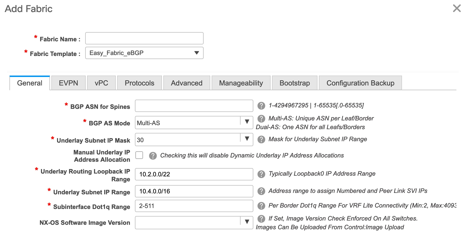
Click Create Fabric, the Add Fabric screen appears.
The fields are explained:
Fabric Name - Enter the name of the fabric.
Fabric Template - From the drop-down menu, choose the Easy_Fabric_11_1 fabric template. The fabric settings for creating a standalone fabric appear.
The tabs and their fields in the screen are explained in the subsequent points. The overlay and underlay network parameters
are included in these tabs.

Note
|
If you are creating a standalone fabric as a potential member fabric of an MSD fabric (used for provisioning overlay networks
for fabrics that are connected through EVPN Multi-Site technology), then browse through the Multi-Site Domain for VXLAN BGP
EVPN Fabrics topic before member fabric creation.
|
-
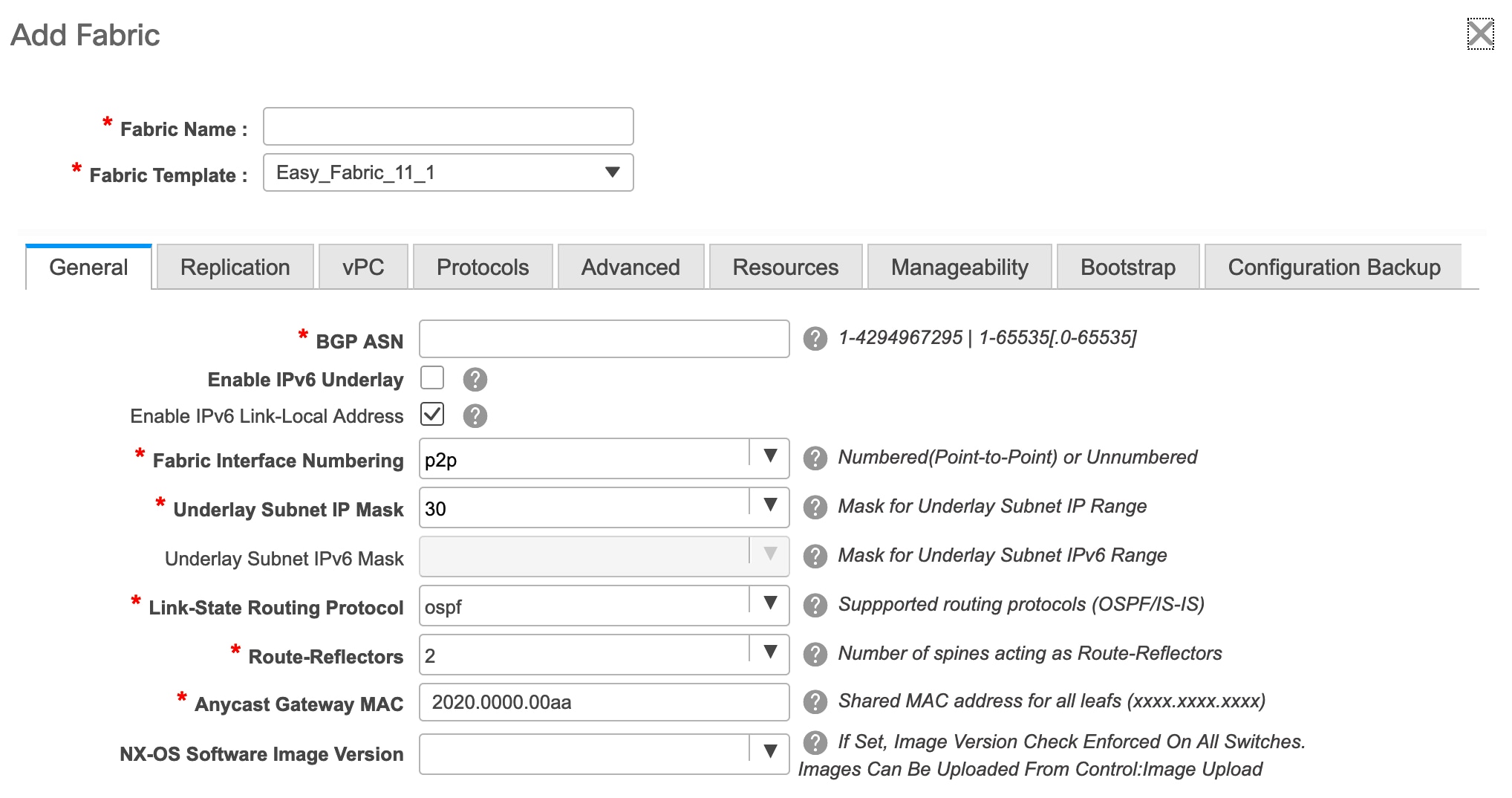
The General tab is displayed by default. The fields in this tab are:
BGP ASN: Enter the BGP AS number the fabric is associated with.
Enable IPv6 Underlay: Enable the IPv6 underlay feature. For information, see IPv6 Underlay Support for Easy Fabric.
Enable IPv6 Link-Local Address: Enables the IPv6 Link-Local address.
Fabric Interface Numbering : Specifies whether you want to use point-to-point (p2p) or unnumbered networks.
Underlay Subnet IP Mask - Specifies the subnet mask for the fabric interface IP addresses.
Underlay Routing Protocol : The IGP used in the fabric, OSPF, or IS-IS.
Route-Reflectors (RRs) – The number of spine switches that are used as route reflectors for transporting BGP traffic. Choose 2 or 4 from the drop-down
box. The default value is 2.
To deploy spine devices as RRs, DCNM sorts the spine devices based on their serial numbers, and designates two or four spine
devices as RRs. If you add more spine devices, existing RR configuration will not change.
Increasing the count - You can increase the route reflectors from two to four at any point in time. Configurations are automatically generated
on the other two spine devices designated as RRs.
Decreasing the count - When you reduce four route reflectors to two, remove the unneeded route reflector devices from the fabric. Follow these
steps to reduce the count from 4 to 2.
-
Change the value in the drop-down box to 2.
-
Identify the spine switches designated as route reflectors.
An instance of the rr_state policy is applied on the spine switch if it is a route reflector. To find out if the policy is applied on the switch, right-click
the switch, and choose View/edit policies. In the View/Edit Policies screen, search rr_state in the Template field. It is displayed on the screen.
-
Delete the unneeded spine devices from the fabric (right-click the spine switch icon and choose Discovery > Remove from fabric).
If you delete existing RR devices, the next available spine switch is selected as the replacement RR.
-
Click Save & Deploy in the fabric topology window.
You can preselect RRs and RPs before performing the first Save & Deploy operation. For more information, see Preselecting Switches as Route-Reflectors and Rendezvous-Points.
Anycast Gateway MAC : Specifies the anycast gateway MAC address.
NX-OS Software Image Version : Select an image from the list.
If you upload Cisco NX-OS software images through the image upload option, the uploaded images are listed in this field. If
you select an image, and save the Fabric Settings, the system checks that all the switches within the fabric have the selected
version. If some devices do not run the image, a warning is prompted to perform an In-Service Software Upgrade (ISSU) to the
specified image. The warning is also accompanied with a Resolve button. This takes the user to the image management screen
with the mismatched switches auto selected for device upgrade/downgrade to the specified NX-OS image specified in Fabric Settings.
Till, all devices run the specified image, the deployment process is incomplete.
If you want to deploy more than one type of software image on the fabric switches, don’t specify any image. If an image is
specified, delete it.
-
Click the Replication tab. Most of the fields are auto generated. You can update the fields if needed.
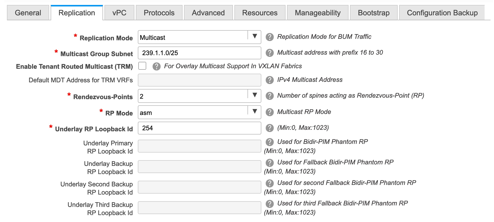
Replication Mode : The mode of replication that is used in the fabric for BUM (Broadcast, Unknown Unicast, Multicast) traffic. The choices
are Ingress Replication or Multicast. When you choose Ingress replication, the multicast related fields get disabled.
You can change the fabric setting from one mode to the other, if no overlay profile exists for the fabric.
Multicast Group Subnet : IP address prefix used for multicast communication. A unique IP address is allocated from this group for each overlay network.
In the DCNM 11.0(1) release, the replication mode change is not allowed if a policy template instance is created for the current
mode. For example, if a multicast related policy is created and deployed, you cannot change the mode to Ingress.
Enable Tenant Routed Multicast (TRM) – Select the check box to enable Tenant Routed Multicast (TRM) that allows overlay multicast traffic to be supported over
EVPN/MVPN in the VXLAN BGP EVPN fabric.
Default MDT Address for TRM VRFs: The multicast address for Tenant Routed Multicast traffic is populated. By default, this address is from the IP prefix specified
in the Multicast Group Subnet field. When you update either field, ensure that the TRM address is chosen from the IP prefix specified in Multicast Group Subnet.
For more information, see Overview of Tenant Routed Multicast.
Rendezvous-Points - Enter the number of spine switches acting as rendezvous points.
RP mode – Choose from the two supported multicast modes of replication, ASM (for Any-Source Multicast [ASM]) or BiDir (for Bidirectional
PIM [BIDIR-PIM]).
When you choose ASM, the BiDir related fields are not enabled. When you choose BiDir, the BiDir related fields are enabled.
Note
|
BIDIR-PIM is supported on Cisco's Cloud Scale Family platforms 9300-EX and 9300-FX/FX2, and software release 9.2(1) onwards.
|
When you create a new VRF for the fabric overlay, this address is populated in the Underlay Multicast Address field, in the Advanced tab.
Underlay RP Loopback ID – The loopback ID used for the rendezvous point (RP), for multicast protocol peering purposes in the fabric underlay.
The next two fields are enabled if you choose BIDIR-PIM as the multicast mode of replication.
Underlay Primary RP Loopback ID – The primary loopback ID used for the phantom RP, for multicast protocol peering purposes in the fabric underlay.
Underlay Backup RP Loopback ID – The secondary loopback ID used for the phantom RP, for multicast protocol peering purposes in the fabric underlay.
Underlay Second Backup RP Loopback Id and Underlay Third Backup RP Loopback Id: Used for the second and third fallback Bidir-PIM Phantom RP.
-
Click the vPC tab. Most of the fields are auto generated. You can update the fields if needed.

vPC Peer Link VLAN – VLAN used for the vPC peer link SVI.
Make vPC Peer Link VLAN as Native VLAN - Enables vPC peer link VLAN as Native VLAN.
vPC Peer Keep Alive option – Choose the management or loopback option. If you want to use IP addresses assigned to the management port and the management
VRF, choose management. If you use IP addresses assigned to loopback interfaces (and a non-management VRF), choose loopback.
If you use IPv6 addresses, you must use loopback IDs.
vPC Auto Recovery Time - Specifies the vPC auto recovery time-out period in seconds.
vPC Delay Restore Time - Specifies the vPC delay restore period in seconds.
vPC Peer Link Port Channel ID - Specifies the Port Channel ID for a vPC Peer Link. By default, the value in this field is 500.
vPC IPv6 ND Synchronize – Enables IPv6 Neighbor Discovery synchronization between vPC switches. The check box is enabled by default. Clear the check
box to disable the function.
vPC advertise-pip - Select the check box to enable the Advertise PIP feature.
You can enable the advertise PIP feature on a specific vPC as well. For more information, see Advertising PIP on vPC.
Enable the same vPC Domain Id for all vPC Pairs: Enable the same vPC Domain ID for all vPC pairs. When you select this field, the vPC Domain Id field is editable.
vPC Domain Id - Specifies the vPC domain ID to be used on all vPC pairs.
vPC Domain Id Range - Specifies the vPC Domain Id range to use for new pairings.
Enable Qos for Fabric vPC-Peering - Enable QoS on spines for guaranteed delivery of vPC Fabric Peering communication. For more information, see QoS for Fabric vPC-Peering.
Note
|
QoS for vPC fabric peering and queuing policies options in fabric settings are mutually exclusive.
|
Qos Policy Name - Specifies QoS policy name that should be same on all fabric vPC peering spines. The default name is spine_qos_for_fabric_vpc_peering.
-
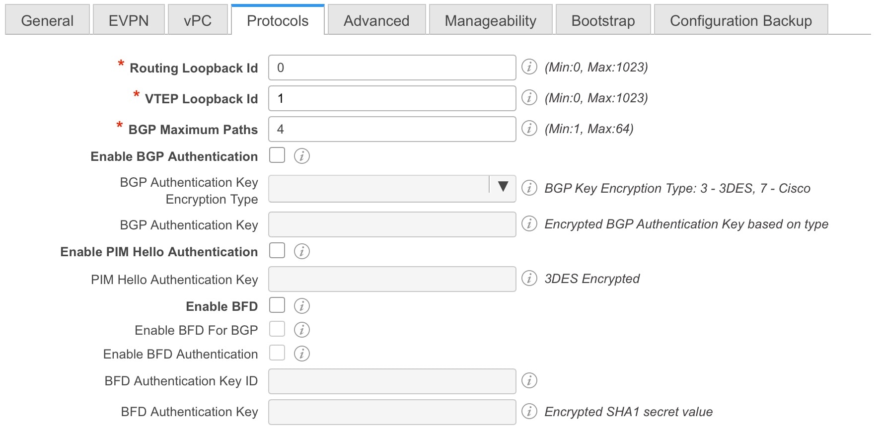
Click the Protocols tab. Most of the fields are auto generated. You can update the fields if needed.
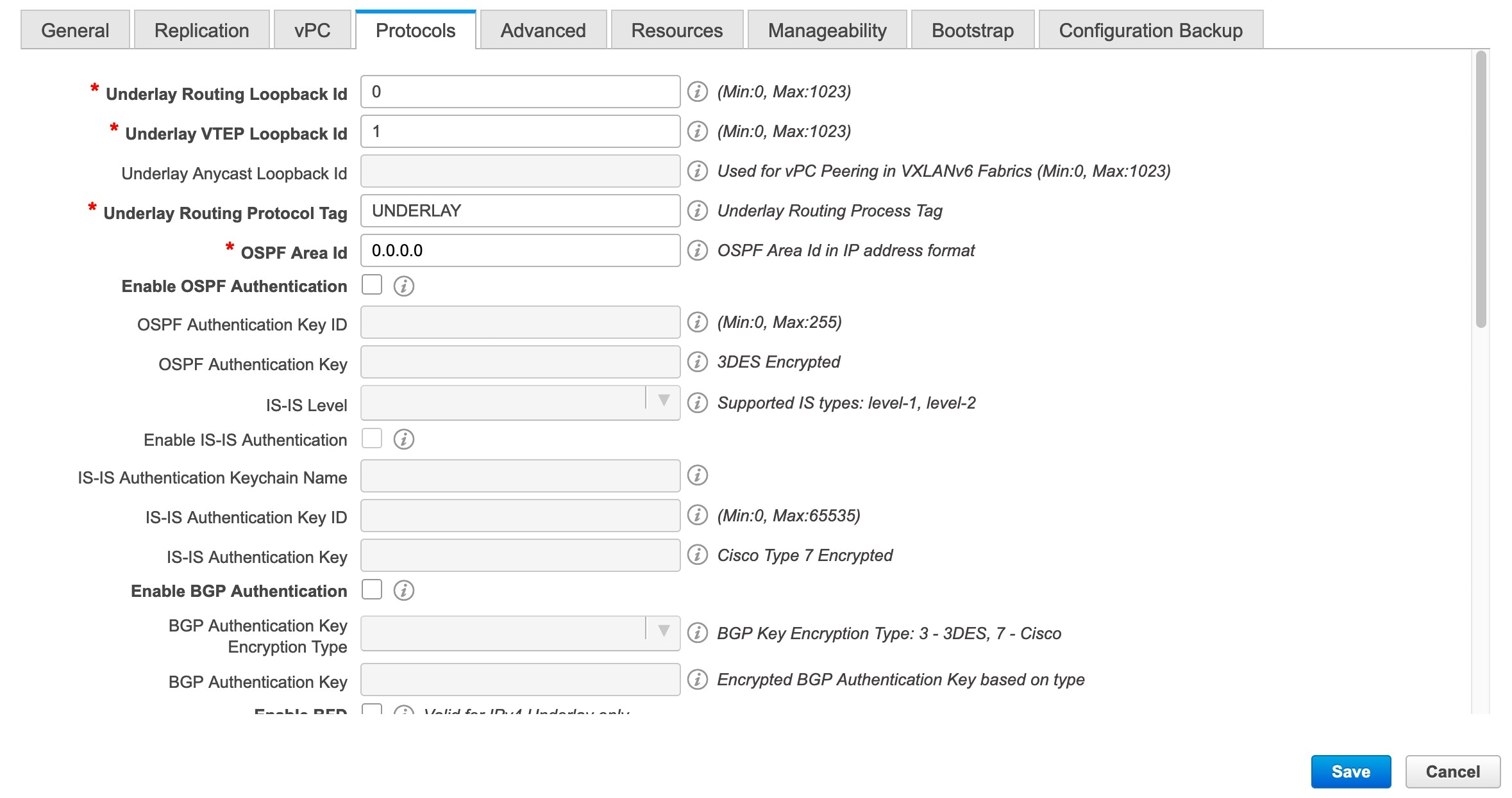

Underlay Routing Loopback Id - The loopback interface ID is populated as 0 since loopback0 is usually used for fabric underlay IGP peering purposes.
Underlay VTEP Loopback Id - The loopback interface ID is populated as 1 since loopback1 is used for the VTEP peering purposes.
Underlay Routing Protocol Tag - The tag defining the type of network.
OSPF Area ID – The OSPF area ID, if OSPF is used as the IGP within the fabric.
Note
|
The OSPF or IS-IS authentication fields are enabled based on your selection in the Underlay Routing Protocol field in the General tab.
|
Enable OSPF Authentication – Select the check box to enable OSPF authentication. Deselect the check box to disable it. If you enable this field, the
OSPF Authentication Key ID and OSPF Authentication Key fields get enabled.
OSPF Authentication Key ID - The Key ID is populated.
OSPF Authentication Key - The OSPF authentication key must be the 3DES key from the switch.
Note
|
Plain text passwords are not supported. Log in to the switch, retrieve the encrypted key and enter it in this field. Refer,
Retrieving the Authentication Key section for details.
|
IS-IS Level - Select the IS-IS level from this drop-down list.
Enable IS-IS Authentication - Select the check box to enable IS-IS authentication. Deselect the check box to disable it. If you enable this field, the
IS-IS authentication fields are enabled.
IS-IS Authentication Keychain Name - Enter the Keychain name, such as CiscoisisAuth.
IS-IS Authentication Key ID - The Key ID is populated.
IS-IS Authentication Key - Enter the Cisco Type 7 encrypted key.
Note
|
Plain text passwords are not supported. Log in to the switch, retrieve the encrypted key and enter it in this field. Refer
the Retrieving the Authentication Key section for details.
|
Enable BGP Authentication - Select the check box to enable BGP authentication. Deselect the check box to disable it. If you enable this field, the
BGP Authentication Key Encryption Type and BGP Authentication Key fields are enabled.
Note
|
If you enable BGP authentication using this field, leave the iBGP Peer-Template Config field blank to avoid duplicate configuration.
|
BGP Authentication Key Encryption Type – Choose the 3 for 3DES encryption type, or 7 for Cisco encryption type.
BGP Authentication Key - Enter the encrypted key based on the encryption type.
Note
|
Plain text passwords are not supported. Log in to the switch, retrieve the encrypted key and enter it in the BGP Authentication
Key field. Refer the Retrieving the Authentication Key section for details.
|
Enable PIM Hello Authentication - Enables the PIM hello authentication.
PIM Hello Authentication Key - Specifies the PIM hello authentication key.
Enable BFD: Select the check box to enable feature bfd on all switches in the fabric. This feature is valid only on IPv4 underlay and the scope is within a fabric.
From Cisco DCNM Release 11.3(1), BFD within a fabric is supported natively. The BFD feature is disabled by default in the
Fabric Settings. If enabled, BFD is enabled for the underlay protocols with the default settings. Any custom required BFD
configurations must be deployed via the per switch freeform or per interface freeform policies.
The following config is pushed after you select the Enable BFD check box:
feature bfd
Note
|
After you upgrade from DCNM Release 11.2(1) with BFD enabled to DCNM Release 11.3(1), the following configurations are pushed
on all P2P fabric interfaces:
no ip redirects
no ipv6 redirects
|
For information about BFD feature compatibility, refer your respective platform documentation and for information about the
supported software images, see Compatibility Matrix for Cisco DCNM.
Enable BFD for iBGP: Select the check box to enable BFD for the iBGP neighbor. This option is disabled by default.
Enable BFD for OSPF: Select the check box to enable BFD for the OSPF underlay instance. This option is disabled by default, and it is grayed out
if the link state protocol is ISIS.
Enable BFD for ISIS: Select the check box to enable BFD for the ISIS underlay instance. This option is disabled by default, and it is grayed out
if the link state protocol is OSPF.
Enable BFD for PIM: Select the check box to enable BFD for PIM. This option is disabled by default, and it is be grayed out if the replication
mode is Ingress.
Here are the examples of the BFD global policies:
router ospf <ospf tag>
   bfd

router isis <isis tag>
  address-family ipv4 unicast
    bfd

ip pim bfd

router bgp <bgp asn>
  neighbor <neighbor ip>
    bfd
Enable BFD Authentication: Select the check box to enable BFD authentication. If you enable this field, the BFD Authentication Key ID and BFD Authentication Key fields are editable.
Note
|
BFD Authentication is not supported when the Fabric Interface Numbering field under the General tab is set to unnumbered. The BFD authentication fields will be grayed out automatically. BFD authentication is valid for only for P2P interfaces.
|
BFD Authentication Key ID: Specifies the BFD authentication key ID for the interface authentication. The default value is 100.
BFD Authentication Key: Specifies the BFD authentication key.
For information about how to retrieve the BFD authentication parameters, see Retrieving the Encrypted BFD Authentication Key.
iBGP Peer-Template Config – Add iBGP peer template configurations on the leaf switches to establish an iBGP session between the leaf switch and route
reflector.
If you use BGP templates, add the authentication configuration within the template and clear the Enable BGP Authentication
check box to avoid duplicate configuration.
In the sample configuration, the 3DES password is displayed after password 3.
router bgp 65000
    password 3 sd8478fswerdfw3434fsw4f4w34sdsd8478fswerdfw3434fsw4f4w
Until Cisco DCNM Release 11.3(1), iBGP peer template for iBGP definition on the leafs or border role devices and BGP RRs were
same. From DCNM Release 11.4(1), the following fields can be used to specify different configurations:
-
iBGP Peer-Template Config – Specifies the config used for RR and spines with border role.
-
Leaf/Border/Border Gateway iBGP Peer-Template Config – Specifies the config used for leaf, border, or border gateway. If this field is empty, the peer template defined in iBGP Peer-Template Config is used on all BGP enabled devices (RRs, leafs, border, or border gateway roles).
In brownfield migration, if the spine and leaf use different peer template names, both iBGP Peer-Template Config and Leaf/Border/Border Gateway iBGP Peer-Template Config fields need to be set according to the switch config. If spine and leaf use the same peer template name and content (except
for the “route-reflector-client” CLI), only iBGP Peer-Template Config field in fabric setting needs to be set. If the fabric settings on iBGP peer templates do not match the existing switch configuration,
an error message is generated and the migration will not proceed.
-
Click the Advanced tab. Most of the fields are auto generated. You can update the fields if needed.

VRF Template and VRF Extension Template: Specifies the VRF template for creating VRFs, and the VRF extension template for enabling VRF extension to other fabrics.
Network Template and Network Extension Template: Specifies the network template for creating networks, and the network extension template for extending networks to other
fabrics.
Site ID - The ID for this fabric if you are moving this fabric within an MSD. The site ID is mandatory for a member fabric to be
a part of an MSD. Each member fabric of an MSD has a unique site ID for identification.
Intra Fabric Interface MTU - Specifies the MTU for the intra fabric interface. This value should be an even number.
Layer 2 Host Interface MTU - Specifies the MTU for the layer 2 host interface. This value should be an even number.
Power Supply Mode - Choose the appropriate power supply mode.
CoPP Profile - Choose the appropriate Control Plane Policing (CoPP) profile policy for the fabric. By default, the strict option is populated.
VTEP HoldDown Time - Specifies the NVE source interface hold down time.
Brownfield Overlay Network Name Format: Enter the format to be used to build the overlay network name during a brownfield import or migration. The network name
should not contain any white spaces or special characters except underscore (_) and hyphen (-). The network name must not
be changed once the brownfield migration has been initiated. See the Creating Networks for the Standalone Fabric section for the naming convention of the network name. The syntax is [<string> | $$VLAN_ID$$] $$VNI$$ [<string>| $$VLAN_ID$$] and the default value is Auto_Net_VNI$$VNI$$_VLAN$$VLAN_ID$$. When you create networks, the name is generated according to the syntax you specify. The following table describes the variables
in the syntax.
|
Variables
|
Description
|
|
$$VNI$$
|
Specifies the network VNI ID found in the switch configuration. This is a mandatory keyword required to create unique network
names.
|
|
$$VLAN_ID$$
|
Specifies the VLAN ID associated with the network.
VLAN ID is specific to switches, hence DCNM picks the VLAN ID from one of the switches, where the network is found, randomly
and use it in the name.
We recommend not to use this unless the VLAN ID is consistent across the fabric for the VNI.
|
|
<string>
|
This variable is optional and you can enter any number of alphanumeric characters that meet the network name guidelines.
|
Example overlay network name: Site_VNI12345_VLAN1234
Note
|
Ignore this field for greenfield deployments. The Brownfield Overlay Network Name Format applies for the following brownfield imports:
|
Enable CDP for Bootstrapped Switch - Enables CDP on management (mgmt0) interface for bootstrapped switch. By default, for bootstrapped switches, CDP is disabled
on the mgmt0 interface.
Enable VXLAN OAM - Enables the VXLAM OAM functionality for devices in the fabric. This is enabled by default. Clear the check box to disable
VXLAN OAM function.
If you want to enable the VXLAN OAM function on specific switches and disable on other switches in the fabric, you can use
freeform configurations to enable OAM and disable OAM in the fabric settings.
Note
|
The VXLAN OAM feature in Cisco DCNM is only supported on a single fabric or site.
|
Enable Tenant DHCP – Select the check box to enable feature dhcp and associated configurations globally on all switches in the fabric. This
is a pre-requisite for support of DHCP for overlay networks that are part of the tenant VRFs.
Note
|
Ensure that Enable Tenant DHCP is enabled before enabling DHCP related parameters in the overlay profiles.
|
Enable NX-API - Specifies enabling of NX-API on HTTPS. This check box is checked by default.
Enable NX-API on HTTP on Port - Specifies enabling of NX-API on HTTP. Enable this check box and the Enable NX-API check box to use HTTP. This check box is checked by default. If you uncheck this check box, the applications that use NX-API and supported by Cisco DCNM, such as Endpoint Locator (EPL),
Layer 4-Layer 7 services (L4-L7 services), VXLAN OAM, and so on, start using the HTTPS instead of HTTP.
Note
|
If you check the Enable NX-API check box and the Enable NX-API on HTTP check box, applications use HTTP.
|
Enable Policy-Based Routing (PBR) - Select this check box to enable routing of packets based on the specified policy. Starting with Cisco NX-OS Release 7.0(3)I7(1)
and later releases, this feature works on Cisco Nexus 9000 Series switches with Nexus 9000 Cloud Scale (Tahoe) ASICs. This
feature is used along with the Layer 4-Layer 7 service workflow. For information on Layer 4-Layer 7 service, refer the Layer 4-Layer 7 Service chapter.
Enable Strict Config Compliance - Enable the Strict Config Compliance feature by selecting this check box. By default, this feature is disabled. For more
information, refer Strict Configuration Compliance.
Enable AAA IP Authorization - Enables AAA IP authorization, when IP Authorization is enabled in the remote authentication server. This is required to
support DCNM in scenarios where customers have strict control of which IP addresses can have access to the switches.
Enable DCNM as Trap Host - Select this check box to enable DCNM as a SNMP trap destination. Typically, for a native HA DCNM deployment, the eth1 VIP
IP address will be configured as SNMP trap destination on the switches. By default, this check box is enabled.
Greenfield Cleanup Option – Enable the switch cleanup option for switches imported into DCNM with Preserve-Config=No, without a switch reload. This
option is typically recommended only for the fabric environments with Cisco Nexus 9000v Switches to improve on the switch
clean up time. The recommended option for Greenfield deployment is to employ Bootstrap or switch cleanup with a reboot. In
other words, this option should be unchecked.
Enable Precision Time Protocol (PTP): Enables PTP across a fabric. When you select this check box, PTP is enabled globally and on core-facing interfaces. Additionally,
the PTP Source Loopback Id and PTP Domain Id fields are editable. For more information, see Precision Time Protocol for Easy Fabric.
PTP Source Loopback Id: Specifies the loopback interface ID Loopback that is used as the Source IP Address for all PTP packets. The valid values
range from 0 to 1023. The PTP loopback ID cannot be the same as RP, Phantom RP, NVE, or MPLS loopback ID. Otherwise, an error
will be generated. The PTP loopback ID can be the same as BGP loopback or user-defined loopback which is created from DCNM.
If the PTP loopback ID is not found during Save & Deploy, the following error is generated:
Loopback interface to use for PTP source IP is not found. Create PTP loopback interface on all the devices to enable PTP feature.
PTP Domain Id: Specifies the PTP domain ID on a single network. The valid values range from 0 to 127.
Enable MPLS Handoff: Select the check box to enable the MPLS Handoff feature. For more information, see the Border Provisioning Use Case in VXLAN BGP EVPN Fabrics - MPLS SR and LDP Handoff chapter.
Underlay MPLS Loopback Id: Specifies the underlay MPLS loopback ID. The default value is 101.
Enable TCAM Allocation: TCAM commands are automatically generated for VXLAN and vPC Fabric Peering when enabled.
Enable Default Queuing Policies: Check this check box to apply QoS policies on all the switches in this fabric. To remove the QoS policies that you applied
on all the switches, uncheck this check box, update all the configurations to remove the references to the policies, and save
and deploy. From Cisco DCNM Release 11.3(1), pre-defined QoS configurations are included that can be used for various Cisco
Nexus 9000 Series Switches. When you check this check box, the appropriate QoS configurations are pushed to the switches in
the fabric. The system queuing is updated when configurations are deployed to the switches. You can perform the interface
marking with defined queuing policies, if required, by adding the required configuration to the per interface freeform block.
From Cisco DCNM Release 11.4(1), the DSCP mapping for QoS 5 has changed from 40 to 46 in the policy template. For DCNM 11.3(1)
deployments that have been upgraded to 11.4(1), you will see the diffs that need to be deployed.
Review the actual queuing policies by opening the policy file in the template editor. From Cisco DCNM Web UI, choose Control > Template Library. Search for the queuing policies by the policy file name, for example, queuing_policy_default_8q_cloudscale. Choose the file and click the Modify/View template icon to edit the policy.
See the Cisco Nexus 9000 Series NX-OS Quality of Service Configuration Guide for platform specific details.
N9K Cloud Scale Platform Queuing Policy: Choose the queuing policy from the drop-down list to be applied to all Cisco Nexus 9200 Series Switches and the Cisco Nexus
9000 Series Switches that ends with EX, FX, and FX2 in the fabric. The valid values are queuing_policy_default_4q_cloudscale and queuing_policy_default_8q_cloudscale. Use the queuing_policy_default_4q_cloudscale policy for FEXes. You can change from the queuing_policy_default_4q_cloudscale policy to the queuing_policy_default_8q_cloudscale policy only when FEXes are offline.
N9K R-Series Platform Queuing Policy: Choose the queuing policy from the drop-down list to be applied to all Cisco Nexus switches that ends with R in the fabric.
The valid value is queuing_policy_default_r_series.
Other N9K Platform Queuing Policy: Choose the queuing policy from the drop-down list to be applied to all other switches in the fabric other than the switches
mentioned in the above two options. The valid value is queuing_policy_default_other.
Enable MACsec - Enables MACsec for the fabric. For more information, see MACsec Support in Easy Fabric and eBGP Fabric.
Freeform CLIs - Fabric level freeform CLIs can be added while creating or editing a fabric. They are applicable to switches across the
fabric. You must add the configurations as displayed in the running configuration, without indentation. Switch level freeform
configurations such as VLAN, SVI, and interface configurations should only be added on the switch. For more information, refer
Enabling Freeform Configurations on Fabric Switches.
Leaf Freeform Config - Add CLIs that should be added to switches that have the Leaf, Border, and Border Gateway roles.
Spine Freeform Config - Add CLIs that should be added to switches with a Spine, Border Spine, Border Gateway Spine, and Super Spine roles.
Intra-fabric Links Additional Config - Add CLIs that should be added to the intra-fabric links.
-
Click the Resources tab.

Manual Underlay IP Address Allocation – Do not select this check box if you are transitioning your VXLAN fabric management to DCNM.
-
By default, DCNM allocates the underlay IP address resources (for loopbacks, fabric interfaces, etc) dynamically from the
defined pools. If you select the check box, the allocation scheme switches to static, and some of the dynamic IP address range
fields are disabled.
-
For static allocation, the underlay IP address resources must be populated into the Resource Manager (RM) using REST APIs.
Refer the Cisco DCNM REST API Reference Guide, Release 11.2(1) for more details. The REST APIs must be invoked after the switches
are added to the fabric, and before you use the Save & Deploy option.
-
The Underlay RP Loopback IP Range field stays enabled if BIDIR-PIM function is chosen for multicast replication.
-
Changing from static to dynamic allocation keeps the current IP resource usage intact. Only future IP address allocation requests
are taken from dynamic pools.
Underlay Routing Loopback IP Range - Specifies loopback IP addresses for the protocol peering.
Underlay VTEP Loopback IP Range - Specifies loopback IP addresses for VTEPs.
Underlay RP Loopback IP Range - Specifies the anycast or phantom RP IP address range.
Underlay Subnet IP Range - IP addresses for underlay P2P routing traffic between interfaces.
Underlay MPLS Loopback IP Range: Specifies the underlay MPLS loopback IP address range.
For eBGP between Border of Easy A and Easy B, Underlay routing loopback and Underlay MPLS loopback IP range must be a unique
range. It should not overlap with IP ranges of the other fabrics, else VPNv4 peering will not come up.
Layer 2 VXLAN VNI Range and Layer 3 VXLAN VNI Range - Specifies the VXLAN VNI IDs for the fabric.
Network VLAN Range and VRF VLAN Range - VLAN ranges for the Layer 3 VRF and overlay network.
Subinterface Dot1q Range - Specifies the subinterface range when L3 sub interfaces are used.
VRF Lite Deployment - Specify the VRF Lite method for extending inter fabric connections.
The VRF Lite Subnet IP Range field specifies resources reserved for IP address used for VRF LITE when VRF LITE IFCs are auto-created.
If you select Back2BackOnly, ToExternalOnly, or Back2Back&ToExternal then VRF LITE IFCs are auto-created.
Auto Deploy Both - This check box is applicable for the symmetric VRF Lite deployment. When you select this check box, it would set the auto
deploy flag to true for auto-created IFCs to turn on symmetric VRF Lite configuration.
This check box can be selected or deselected when the VRF Lite Deployment field is not set to Manual. In the case, a user explicitly unchecks the auto-deploy field for any auto-created IFCs, then
the user input is always given the priority. This flag only affects the new auto-created IFC and it does not affect the existing
IFCs.
VRF Lite Subnet IP Range and VRF Lite Subnet Mask – These fields are populated with the DCI subnet details. Update the fields as needed.
The values shown in your screen are automatically generated. If you want to update the IP address ranges, VXLAN Layer 2/Layer
3 network ID ranges or the VRF/Network VLAN ranges, ensure the following:
Note
|
When you update a range of values, ensure that it does not overlap with other ranges. You should only update one range of
values at a time. If you want to update more than one range of values, do it in separate instances. For example, if you want
to update L2 and L3 ranges, you should do the following.
-
Update the L2 range and click Save.
-
Click the Edit Fabric option again, update the L3 range and click Save.
|
Service Network VLAN Range - Specifies a VLAN range in the Service Network VLAN Range field. This is a per switch overlay service network VLAN range.
The minimum allowed value is 2 and the maximum allowed value is 3967.
Route Map Sequence Number Range - Specifies the route map sequence number range. The minimum allowed value is 1 and the maximum allowed value is 65534.
-
Click the Manageability tab.

The fields in this tab are:
DNS Server IPs - Specifies the comma separated list of IP addresses (v4/v6) of the DNS servers.
DNS Server VRFs - Specifies one VRF for all DNS servers or a comma separated list of VRFs, one per DNS server.
NTP Server IPs - Specifies comma separated list of IP addresses (v4/v6) of the NTP server.
NTP Server VRFs - Specifies one VRF for all NTP servers or a comma separated list of VRFs, one per NTP server.
Syslog Server IPs – Specifies the comma separated list of IP addresses (v4/v6) IP address of the syslog servers, if used.
Syslog Server Severity – Specifies the comma separated list of syslog severity values, one per syslog server. The minimum value is 0 and the maximum
value is 7. To specify a higher severity, enter a higher number.
Syslog Server VRFs – Specifies one VRF for all syslog servers or a comma separated list of VRFs, one per syslog server.
AAA Freeform Config – Specifies the AAA freeform configurations.
If AAA configurations are specified in the fabric settings,
switch_freeform PTI with source as
UNDERLAY_AAA and description as AAA
Configurations will be created.
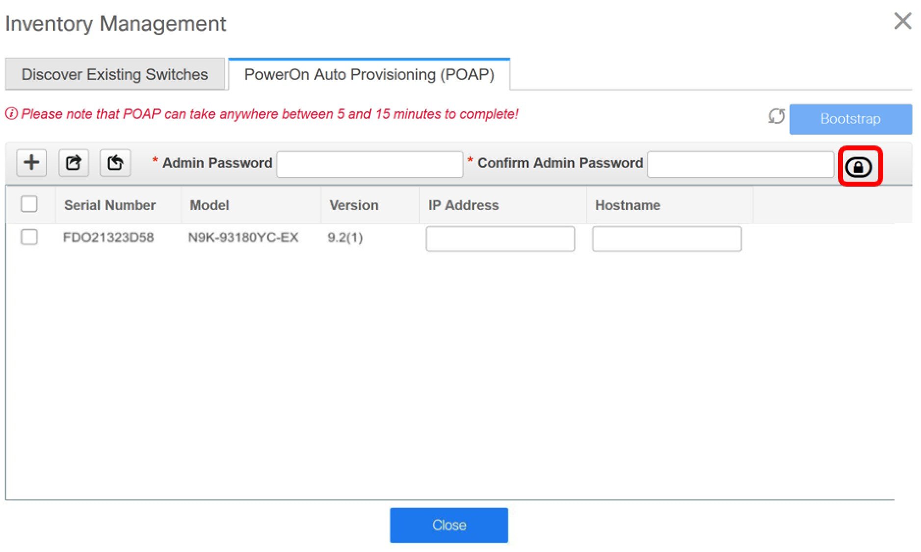
- Click the Bootstrap tab.

Enable Bootstrap - Select this check box to enable the bootstrap feature. Bootstrap allows easy day-0 import and bring-up of new devices into
an existing fabric. Bootstrap leverages the NX-OS POAP functionality.
After you enable bootstrap, you can enable the DHCP server for automatic IP address assignment using one of the following
methods:
-
External DHCP Server: Enter information about the external DHCP server in the Switch Mgmt Default Gateway and Switch Mgmt IP Subnet Prefix fields.
-
Local DHCP Server: Enable the Local DHCP Server check box and enter details for the remaining mandatory fields.
Enable Local DHCP Server - Select this check box to initiate enabling of automatic IP address assignment through the local DHCP server. When you select
this check box, the DHCP Scope Start Address and DHCP Scope End Address fields become editable.
If you do not select this check box, DCNM uses the remote or external DHCP server for automatic IP address assignment.
DHCP Version – Select DHCPv4 or DHCPv6 from this drop-down list. When you select DHCPv4, the Switch Mgmt IPv6 Subnet Prefix field is disabled. If you select DHCPv6, the Switch Mgmt IP Subnet Prefix is disabled.
Note
|
Cisco Nexus 9000 and 3000 Series Switches support IPv6 POAP only when switches are either Layer-2 adjacent (eth1 or out-of-band
subnet must be a /64) or they are L3 adjacent residing in some IPv6 /64 subnet. Subnet prefixes other than /64 are not supported.
|
DHCP Scope Start Address and DHCP Scope End Address - Specifies the first and last IP addresses of the IP address range to be used for the switch out of band POAP.
Switch Mgmt Default Gateway - Specifies the default gateway for the management VRF on the switch.
Switch Mgmt IP Subnet Prefix - Specifies the prefix for the Mgmt0 interface on the switch. The prefix should be between 8 and 30.
DHCP scope and management default gateway IP address specification - If you specify the management default gateway IP address 10.0.1.1 and subnet mask 24, ensure that the DHCP scope is within
the specified subnet, between 10.0.1.2 and 10.0.1.254.
Switch Mgmt IPv6 Subnet Prefix - Specifies the IPv6 prefix for the Mgmt0 interface on the switch. The prefix should be between 112 and 126. This field is
editable if you enable IPv6 for DHCP.
Enable AAA Config – Select this check box to include AAA configurations from the Manageability tab as part of the device startup config post
bootstrap.
Bootstrap Freeform Config - (Optional) Enter additional commands as needed. For example, if you require some additional configurations to be pushed
to the device and be available post device bootstrap, they can be captured in this field, to save the desired intent. After
the devices boot up, they will contain the configuration defined in the Bootstrap Freeform Config field.
Copy-paste the running-config to a freeform config field with correct indentation, as seen in the running configuration on the NX-OS switches. The freeform config must match
the running config. For more information, see Resolving Freeform Config Errors in Switches.
DHCPv4/DHCPv6 Multi Subnet Scope - Specifies the field to enter one subnet scope per line. This field is editable after you check the Enable Local DHCP Server check box.
The format of the scope should be defined as:
DHCP Scope Start Address, DHCP Scope End Address, Switch Management Default Gateway, Switch Management Subnet Prefix
For example: 10.6.0.2, 10.6.0.9, 10.6.0.1, 24
-
Click the Configuration Backup tab. The fields on this tab are:

Hourly Fabric Backup: Select the check box to enable an
hourly backup of fabric configurations and the intent.
The hourly backups are triggered during the first
10 minutes of the hour.
Scheduled Fabric Backup: Check the check box to enable a
daily backup. This backup tracks changes in running configurations on the fabric
devices that are not tracked by configuration compliance.
Scheduled Time: Specify the scheduled backup time in a
24-hour format. This field is enabled if you check the Scheduled
Fabric Backup check box.
Select both the check boxes to enable both back up processes.
The backup process is initiated after you click
Save.
The scheduled backups are triggered exactly at the
time you specify with a delay of up to two minutes. The scheduled backups are
triggered regardless of the configuration deployment status.
The backup
configuration files are stored in the following path in DCNM:
/usr/local/cisco/dcm/dcnm/data/archive
The number
of archived files that can be retained is set in the # Number of
archived files per device to be retained: field in the
Server Properties window.
Note
|
To trigger an
immediate backup, do the following:
-
Choose Control > Fabric Builder. The Fabric
Builder screen comes up.
-
Click within the specific fabric box. The fabric topology screen
comes up.
-
From the Actions pane at the left part of the
screen, click Re-Sync Fabric.
|
You can also initiate the fabric backup in the fabric topology window. Click
Backup Now in the Actions
pane.
-
Click ThousandEyes Agent tab. This feature is supported on Cisco DCNM Release 11.5(3) only. For more information, refer to Configuring Global Settings for ThousandEyes Enterprise Agent.
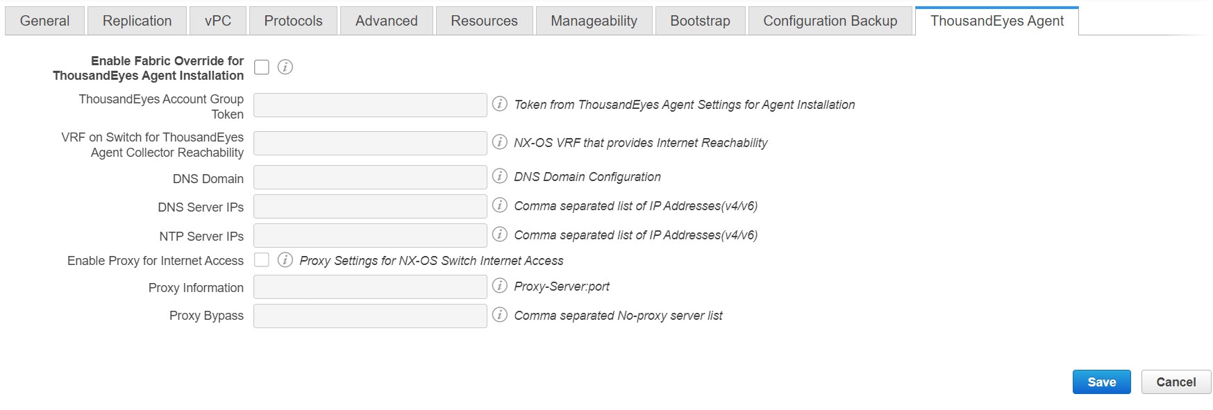
The fields on this tab are:
Note
|
The fabric settings for ThousandEyes Agent overwrites the global settings and applies the same configuration for all the ThousandEyes
Agent installed on switches in that fabric.
|
-
Enable Fabric Override for ThousandEyes Agent Installation: Select the check box to enable the ThousandEyes Enterprise Agent on the fabric.
-
ThousandEyes Account Group Token: Specifies ThousandEyes Enterprise Agent account group token for installation.
-
VRF on Switch for ThousandEyes Agent Collector Reachability: Specifies the VRF data which provides internet reachability.
-
DNS Domain: Specifies the switch DNS domain configuration.
-
DNS Server IPs: Specifies the comma separated list of IP addresses (v4/v6) of Domain Name System (DNS) server. You can enter a maximum of
three IP addresses for the DNS Server.
-
NTP Server IPs: Specifies comma separated list of IP addresses (v4/v6) of Network Time Protocol (NTP) server. You can enter a maximum of
three IP addresses for the NTP Server.
-
Enable Proxy for Internet Access: Select the check box to enable the proxy setting for NX-OS switch internet access.
-
Proxy Information: Specifies the proxy server port information.
-
Proxy Bypass: Specifies the server list for which proxy is bypassed.
-
Click Save after filling and updating relevant information. A note appears briefly at the bottom right part of the screen, indicating
that the fabric is created. When a fabric is created, the fabric page comes up. The fabric name appears at the top left part
of the screen.
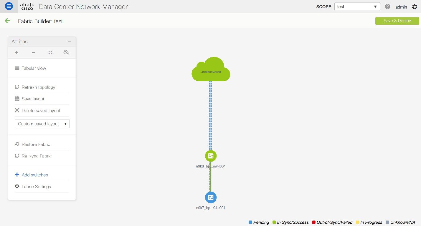
(At the same time, the newly created fabric instance appears on the Fabric Builder screen. To go to the Fabric Builder screen, click the left arrow (←) button above the Actions pane [to the left of the screen]).
The Actions pane allows you to perform various functions. One of them is the Add switches option to add switches to the fabric. After you create a fabric, you should add fabric devices. The options are explained:
-
Tabular View - By default, the switches are displayed in the topology view. Use this option to view switches in the tabular view.
-
Refresh topology - Allows you to refresh the topology.
-
Save Layout – Saves a custom view of the topology. You can create a specific view in the topology and save it for ease of use.
-
Delete saved layout – Deletes the custom view of the topology
-
Topology views - You can choose between Hierarchical, Random and Custom saved layout display options.
-
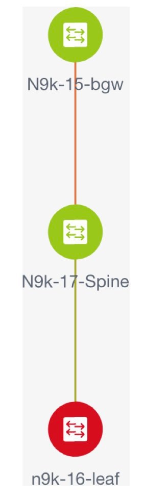
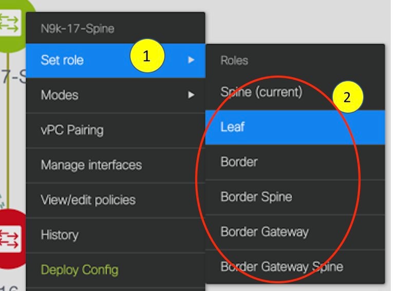
Hierarchical - Provides an architectural view of your topology. Various Switch Roles can be defined that draws the nodes on how you configure
your CLOS topology.
-
Random - Nodes are placed randomly on the window. DCNM tries to make a guess and intelligently place nodes that belong together
in close proximity.
-
Custom saved layout - You can drag nodes around to your liking. Once you have the positions as how you like, you can click Save Layout to remember
the positions. Next time you come to the topology, DCNM will draw the nodes based on your last saved layout positions.
-
Restore Fabric – Allows you to restore the fabric to a prior DCNM configuration
state (one month back, two months back, and so on). For more
information, see the Restore Fabric section.
-
Backup Now: You can initiate a fabric backup manually by clicking Backup Now. Enter a name for the tag and click OK. Regardless of the settings you choose under the Configuration Backup tab in the Fabric Settings dialog box, you can initiate a backup using this option.
-
Resync Fabric - Use this option to resynchronize DCNM state when there is a large
scale out-of-band change, or if configuration changes do not register in
the DCNM properly. The resync operation does a full CC run for the
fabric switches and recollects “show run” and “show run all” commands
from the switches. When you initiate the re-sync process, a progress
message is displayed on the window. During the re-sync, the running
configuration is taken from the switches. Then, the Out-of-Sync/In-Sync
status for the switch is recalculated based on the intent or expected
configuration defined in DCNM versus the current running configuration
that was taken from the switches.
-
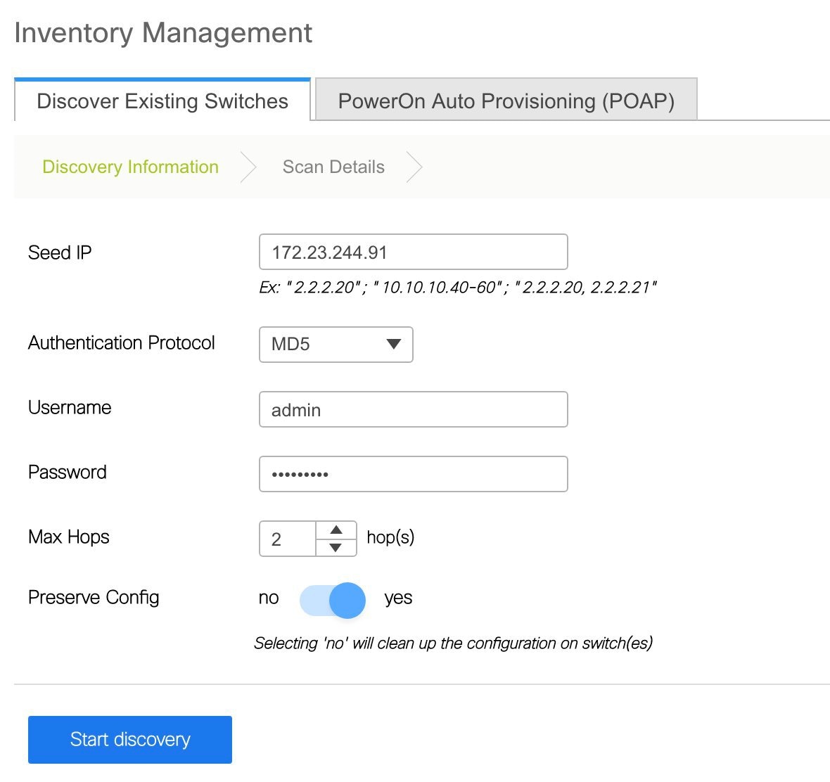
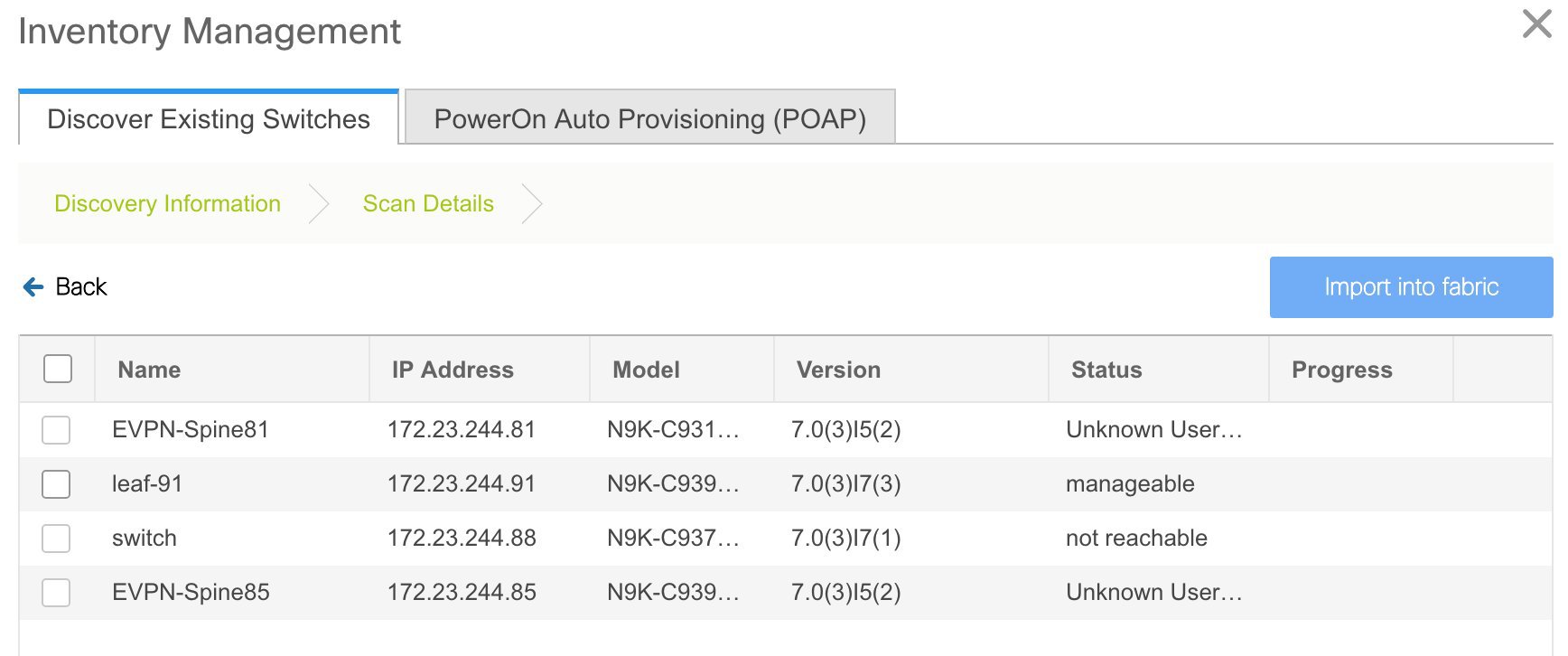
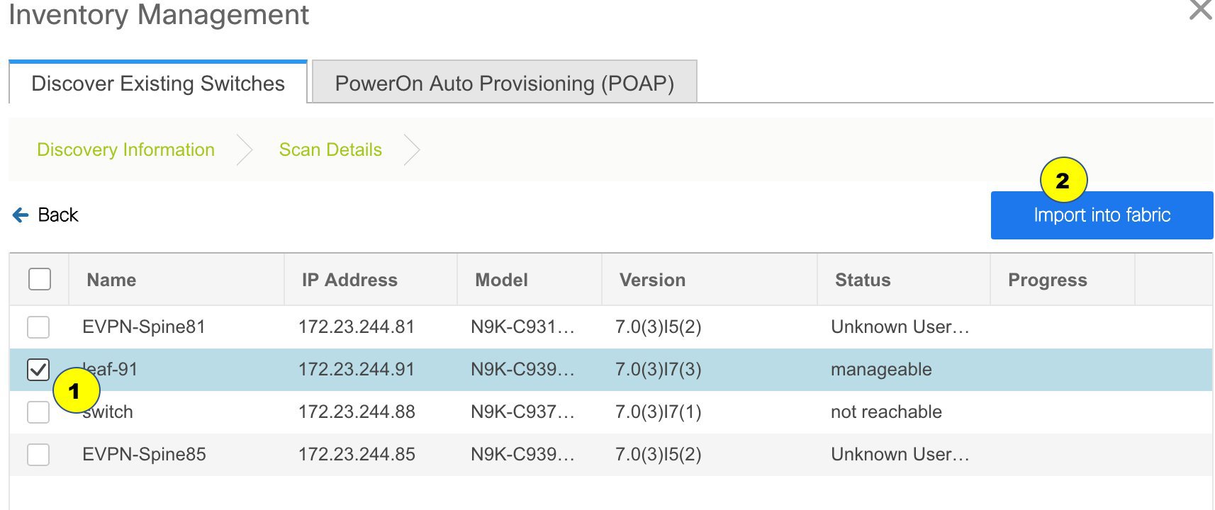
Add Switches – Allows you to add switch instances to the fabric.
-
Fabric Settings – Allows you to view or edit fabric settings.
-
Cloud icon - Click the Cloud icon to display (or not display) an Undiscovered cloud.
When you click the icon, the Undiscovered cloud and its links to the selected fabric topology are not displayed.
Click the Cloud icon again to display the Undiscovered cloud.


 Feedback