LEDs

Chassis LEDs

On the NCS-57B1 chassis, the STATUS, ALARM, SYNC, and FAN LEDs are located at the far-left of the front panel. Power and GNSS LEDs are located at the far-right of the front panel, just below the USB port.

Figure 1. NCS-57B1 Chassis LEDs

1

POWER LED

2

GNSS LED

On the NCS-57C3-MOD chassis, the STATUS and ATTN LEDs are located on the lower-right of the chassis. The SYNC and GNSS LEDs are located below the RPs.

See Route Processor Card LEDs for the NC57-MOD-RP2-E route processor LEDs.
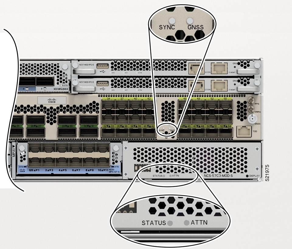
Figure 2. NCS-57C3-MOD Chassis LEDs
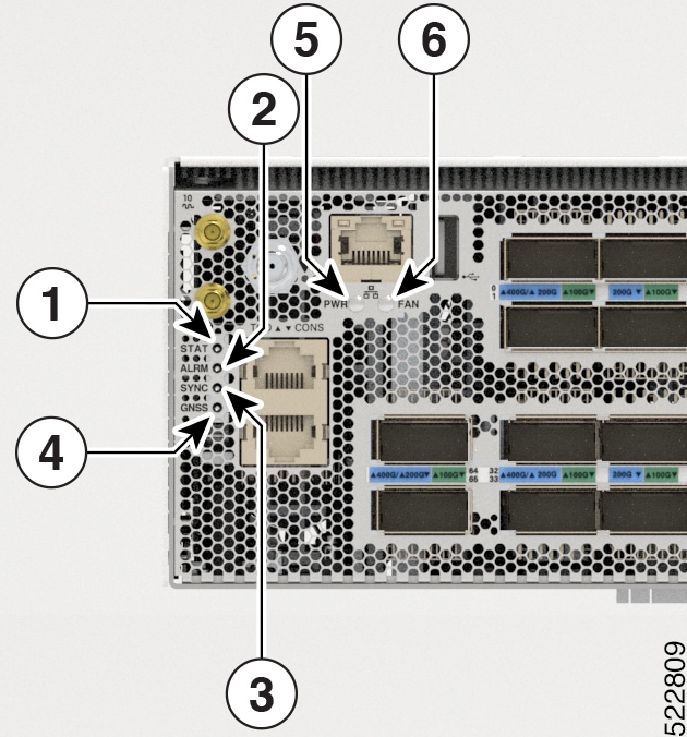
Figure 3. NCS-57D2 Chassis LEDs

1

STAT LED

4

GNSS

2

ALRM

5

PWR

3

SYNC

6

FAN

Table 1. LED Descriptions
LED Color Status

STAT

Green

The module is operational and has no active major or critical alarms.

Blinking Amber

The module is booting up.

Amber

Host kernel booted and is ready to start XR.

Off

The module is powered-off.

ALRM (ALARM)

Red

Critical alarm - system-scope (including RP0).

Amber

Major alarm - system-scope (including RP0).

Off

No alarm.

SYNC

Green

SyncE PLL is locked to an input source.

Amber

SyncE PLL not-locked to any input source.

Off

SyncE not configured.

FAN

Green

Fans are working normally.

Amber

System is operating with one fan failure.

Red

Missing a fan or multiple fan failures.

POWER (PWR)

Off

Chassis not receiving power.

Green

Chassis powered on and normal.

Amber

Chassis powered off and in retry mode due to thermal or fan failure.

Red

Chassis power failure.

Power supply failure, due to one of the following conditions:

  • Over voltage

  • Over current

  • Over Temperature

  • Fan failure

GNSS

Off

GNSS is not configured.

Green

GNSS is locked to an RF input (Satellites).

Amber

GNSS Receiver not-locked RF input (Satellites).

On the NCS-57C1 chassis, the STS (status) and ALM (alarm) LEDs are located at the top right corner of the front panel. No LEDs are present for SYNC and GNSS interfaces.
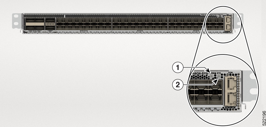
Figure 4. NCS-57C1 Chassis LEDs

1

STS LED

2

ALM LED

Table 2. LED Descriptions
LED Color Status

STS (STATUS)

Green

The module is operational.

Blinking Amber (slow)

The module is booting up.

Blinking Amber (fast)

The module is booting up, shutting down, or the SysAdmin VM is being reloaded.

Off

The module is powered-off.

ALM (ALARM)

Red

Critical alarm.

Amber

Major alarm.

Blinking Amber

Minor alarm.

Off

No alarm.

Route Processor Card LEDs

On the NC57-MOD-RP2-E route processor card, the Status (STS), Active (ACT), and Attention (ATTN) LEDs are located on the lower left front of the route processor card. The management port link and active LEDs are located immediately below the port on the front of the module.

Figure 5. NC57-MOD-RP2-E LEDs

1

STS (Status) LED

2

ACT (Active) LED

3

Attention (ATTN) LED

Table 3. Route Processor Card LED Descriptions

LED

Color

Status

STS (Status)

Green

This module is operational.

Flashing amber

The module is booting up or shutting down.

Flashing red

The module has active major or critical alarms.

Amber

Host kernel booted and is ready to start System Administrator VM.

Red

Either of the following conditions:

  • The module has detected a slot ID parity error and will not power on or boot up.

  • The module is not fully inserted.

Off

The module is not receiving power.

ACT (Active)

Green

XR VM is operational and is in the active redundancy role on this module.

Amber

XR VM is operational and is in the standby redundancy role on this module.

Off

XR VM is not operational on this module.

ATTN (Attention)

Flashing blue

The operator has activated this LED to identify this module in the chassis.

Off

This module is not being identified.

Management port LINK

Green

The management port is linked up.

Off

The management port is not linked up.

Management port ACT

Flashing green

The management port is transmitting or receiving.

Off

The management port is not transmitting or receiving.

Port Status LEDs

The front panel of the NCS-57B1 chassis consists of the following ports for data path connectivity through optical modules:

  • NCS-57B1-5DSE-SYS: x24 QSFP28 ports, x5 QSFP-DD

  • NCS-57B1-6D24-SYS: x24 QSFP28 ports, x6 QSFP-DD

The front panel of the NCS-57C1 chassis consists of the following ports for data path connectivity through optical modules:

  • NCS-57C1: x6 QSFP-DD ports, x16 SFP-50G ports, and x32 SFP-25G ports


Note


In the NCS-57C1 routers, there are additional thermal vent perforations next to the port status LEDs. These perforations are meant to provide additional air flow for cooling the chassis. The LED status of a port can be viewed from these perforations as well.


The front panel of the NCS-57D2 chassis consists of the 66 QSFP-DD ports for data path connectivity through optical modules:

Each port consists a bi-color (Green and Amber) LED for indicating various status information of the optical ports.

Table 4. NCS-57B1, NCS-57C1, NCS-57D2 Port Status LEDs (one per port)

LED Color

Description

Off

Port is administratively shut down.

Green

Port is administratively enabled and the link is up.

Amber

Port is administratively enabled and the link is down.

Port Status LED Display

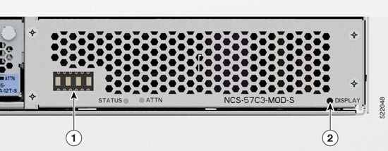
The NCS-57C3-MOD front panel LED display shows the status of the ports.

1

Port Status LED Display

2

DISPLAY Mode Button

The display uses a ##BB format that shows the port number (##) and the status (BB). Status can be green (GN) or yellow (YL) or red (RD). The display cycles through each port number in 1-second intervals.

By default, the display shows all ports and their status. You can change the display mode to show only ports that are in yellow (YL) state by pressing the DISPLAY button for less than 4 seconds and release. To return to the default behavior, press and hold the DISPLAY button for more than 5 seconds and release.

Table 5. NCS-57C3 Port Status LED Display

LED Display

Description

XR Show Controller LED Status

GN

Port is administratively enabled, link is up.

Green

YL

Port is administratively enabled, link is down.

Yellow

RD

Port is administratively shut down.

No option to print

MPA LEDs

The STATUS LED is located on the front left of the MPA and the attention (ATTN) is located on the front right of the MPA. The Link LED for each port is located either between the two rows of ports (each of these LEDs is a triangle pointing to the port above or below the LED) or under the port.

LED Color Status

ATTN

Flashing blue

The operator has activated this LED to identify this MPA in the chassis.

Off

This LED is not being used.

STATUS

Green

This MPA is operational.

Amber

Either of the following conditions:

  • The MPA has detected a slot ID parity error and will not power on or boot up.

  • The MPA is not fully inserted.

Flashing amber

The MPA is booting up or shutting down.

Off

The MPA is powered-off and can now be safely removed.

Link (for each port)

Green

The port is active.

Orange

The port is disabled by the operator or is not initializing.

Flashing orange

The port is faulty and disabled.

Off

The port is not active or the link is not connected.

Management Port LEDs

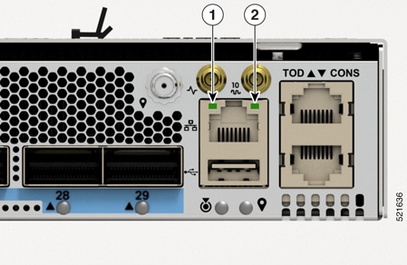
The Management Port LEDs are located at the right-side on the front panel of the NCS-57B1 and NCS-57C3 chassis.

Figure 6. NCS-57B1 and NCS-57C3 Management Port LEDs

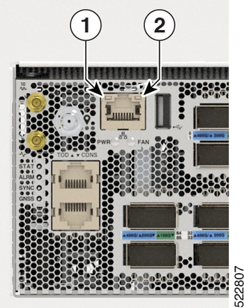
The Management Port LEDs are located at the left-side on the front panel of the NCS-D2 chassis.

Figure 7. NCS-57D2 Management Port LEDs

1

Port Activity

2

Port Link

Table 6. NCS-57B1, NCS-57C3, and NCS-57D2 Management Port LEDs Description

LED

Color

Status

Port Activity

Green

The ethernet link is up and operational.

Off

The ethernet link is down.

Port Link

Green Blinking

The port is either receiving or transmitting packets.

Off

No packets are being received or transmitted.

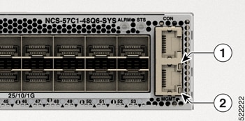
The Management Port LEDs are located at the bottom right-side on the front panel of the NCS-57C1-48Q6-SYS chassis.

Figure 8. NCS-57C1 Management Port LEDs

1

Port Activity

2

Port Link

Table 7. NCS-57C1 Management Port LEDs Description

Color

Status

Green

The 1000M link is up and operational.

Green Blinking

The port is either receiving or transmitting packets at 1000M.

Green and Red

The 100M link is up and operational.

Green and Red Blinking

The port is either receiving or transmitting packets at 100M.

Red

The 10M link is up and operational.

Red Blinking

The port is either receiving or transmitting packets at 100M.

Off

The link is down.

Fan Module and Fan Tray LED

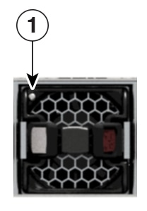
The NCS-57B1 and NCS-57C1 fan module LED is located on the top-left corner of the module.

Figure 9. NCS-57B1 or NCS-57C1 Fan Module LED

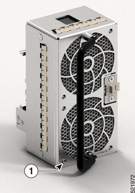
The NCS-57C3-MOD fan tray LED is located on the bottom-left corner of the module.

Figure 10. NCS-57C3-MOD Fan Tray LED

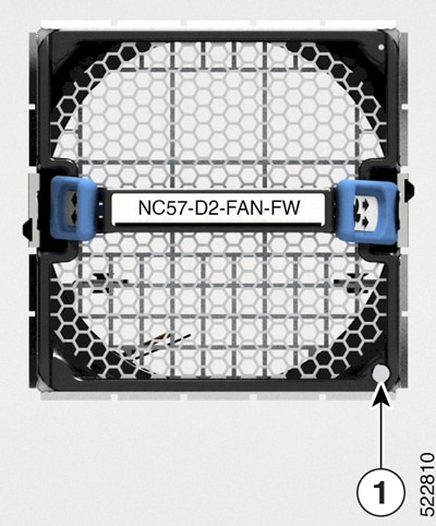
The NCS-57D2 fan tray LED is located on the bottom-right corner of the module.

Figure 11. NCS-57D2 Fan Tray LED

1

Status LED location

LED

Color

Status

STATUS

Green

Fan is operating normally.

Red

Fan failure.

Off

Fan is not receiving power.

Power Supply LED

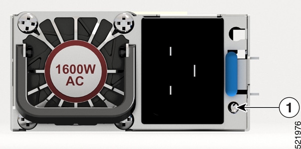
In NCS 57B1 and NCS-57C3-MOD routers, the power supply LED is located on the lower-right corner portion of the power module.

Figure 12. NCS 57B1 Power Supply LED
Figure 13. NCS-57C3-MOD Power Supply LED

1

Power supply LED

In the NCS-57D2 router, the DC power supply LED is located on the top-right corner portion of the power module.

Figure 14. NCS-57D2 DC Power Module

1

Power supply LED

In the NCS-57D2 router, the AC power supply LED is located on the top-right corner portion of the power module.

Figure 15. NCS-57D2 AC Power Module

1

Power supply LED

Table 8. Power Supply LED Descriptions

LED

Color

Status

STATUS

Green

Power supply is on and transmitting power to the router.

Blinking Green

Power supply is connected to input power source but not transmitting power to the router.

Amber

Power supply failure, due to one of the following conditions:

  • Over Voltage

  • Over Current

  • Over Temperature

  • Fan Failure

Blinking Amber

Power supply is operating but a warning condition has occurred, due to one of the following conditions:

  • High temperature

  • High power

  • Slow fan

Off

Power supply units are not receiving power.

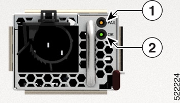
In the NCS-57C1 router, the power supply LEDs are located on the top-right corner portion of the power module. Each power module has an OK and a FAIL LED.

Figure 16. NCS-57C1 Power Supply LED

1

Fail

2

OK

Table 9. NCS-57C1 Power Supply LED Descriptions

OK LED

FAIL LED

Status

Green

Off

Power supply is on and supplying power to the router.

Flashing green

Off

Power supply is connected to input power source but not supplying power to the router. The power supply might not be properly installed in the chassis.

Off

Off

Either all of the installed power supplies are not receiving power or an uninstalled power supply is not receiving power.

Off

Flashing amber

Power supply is operating but a warning condition has occurred—possibly one of the following conditions:

  • High temperature

  • High power

  • Slow power supply fan

  • Low voltage

  • Power supply is installed in the chassis but was disconnected from the power source

Off

Amber

Power supply failure—possibly one of the following conditions:

  • Over voltage

  • Over current

  • Over temperature

  • Power supply fan failure