NCS 5700 Router Overview

Cisco NCS 5700 Router Overview

The Cisco NCS 5700 series fixed-port routers provide aggregation, distributed core, and peering fabric.

The Cisco NCS 5700 series offers two types of systems. Those without external-TCAM (non-SE) rely only on the on-chip resources available for feature scale. The second type of system is equipped with external-TCAM (-SE) which provides an extended scale in addition to the on-chip scale. These systems provide functionality vital to both Top of Rack (ToR) and modern spine-and-leaf architectures.

NCS-57B1

The NCS-57B1 routers provide a power-efficient package with 4.8 Terabits of 400GE/100GE optimized forwarding capacity.

Table 1. Cisco NCS-57B1 Chassis Variants

Variant

Port Configuration

NCS-57B1-5D24H-SE (Perpetual Licensing)

NCS-57B1-5DSE-SYS (Flexible Consumption Model)

Also known as SE variant

A total of 29 ports:

  • 24x100G QSFP-DD

  • 5x400G QSFP-DD

NCS-57B1-6D24H-S (Perpetual Licensing)

NCS-57B1-6D24-SYS (Flexible Consumption Model)

Also known as non-SE variant

A total of 30 ports:

  • 24x100G QSFP-DD

  • 6x400G QSFP-DD

For more information on its features and benefits, see the Cisco NCS-57B1 Fixed Chassis Data Sheet.

NCS-57C3-MOD

The NCS-57C3-MOD routers provide a power-efficient package with up to 2.4 Terabits of optimized forwarding capacity.

Table 2. Cisco NCS-57C3-MOD Chassis Variants

Variant

Port Configuration

NCS-57C3-MOD-SE-S (Perpetual Licensing)

NCS-57C3-MODS-SYS (Flexible Consumption Model)

Also known as SE variant

A total of 52 ports:

  • 48 ports of 25G SFP28

  • 4 ports of 100G QSFP28

In addition, the chassis has 3 Modular Port Adapter (MPA) slots. See Modular Port Adapters for information on MPAs.

NCS-57C3-MOD-S (Perpetual Licensing)

NCS-57C3-MOD-SYS (Flexible Consumption Model)

Also known as non-SE variant

A total of 56 ports:

  • 48 ports of 25G SFP28

  • 8 ports of 100G QSFP28

In addition, the chassis has 3 Modular Port Adapter (MPA) slots. See Modular Port Adapters for information on MPAs.


Note


  • The NCS-57C3 router does not support auto negotiation when the ports are configured in the 1Gbps mode. As a result, 1G copper transceiver modules operating on the NCS-57C3 router cannot detect link failures.


The dimensions of the NCS-57C3-MOD router, with and without fans and power supplies, are shown below.

Figure 1. NCS-57C3-MOD Dimensions

For more information on its features and benefits, see the Cisco NCS-57C3 Fixed Chassis Data Sheet.

NCS-57C1 Chassis Variants

The NCS-57C1 routers provide a power-efficient package with 4 Terabits total port bandwidth and 2.4 Terabits forwarding capacity.

Table 3. Cisco NCS-57C1 Chassis Variants

Variant

Port Configuration

NCS-57C1-48Q6D-S (Perpetual Licensing)

NCS-57C1-48Q6-SYS (Flexible Consumption Model)

A total of 54 ports:

  • 4 ports of 400G QSFP-DD

  • 2 ports of 4x100G QSFP-DD

  • 16 ports of 50G SFP+ (also supports traffic speed of 10G/25G/1G)

  • 32 ports of 25G SFP+ (also supports traffic speed of 10G/1G)

Note


For 1G interface speed, autonegotiation is not supported.

For more information on its features and benefits, see the Cisco NCS-57C1 Fixed Chassis Data Sheet.

NCS-57D2 Chassis Variants

The NCS-57D2 routers provide a power-efficient package with 7.2 Terabits (Tbps) total port bandwidth and 7.2 Terabits (Tbps) forwarding capacity.

Table 4. Cisco NCS-57D2 Chassis Variants

Variant

Port Configuration

NCS-57D2-18DD-SYS (Flexible Consumption Model)

2-RU router with a total of 66 QSFP-DD ports:

  • 18 ports of 400G

    (or)
  • 34 ports of 200G

    (or)
  • 66 ports of 100G

For more information on its features and benefits, see the NCS-57D2-18DD Fixed Chassis Data Sheet.

Field Replaceable Units

The NCS 5700 series fixed-port routers support the following FRUs:

  • Fan modules (NCS-57B1/NCS-57C1/NCS-57D2) and fan trays (NCS-57C3-MOD)

  • Power Supply Units

  • Modular Port Adapters (MPAs)—supported on the NCS-57C3-MOD routers

  • Route Processors—supported on the NCS-57C3-MOD routers

All FRUs support OIR (Online Insertion and Removal).

Fan Modules and Fan Trays

Fans are responsible for cooling the system and to maintain proper airflow through the system. The fan modules work with N+1 redundancy.

The NCS-57B1 router has 6 latched fan modules that install into the chassis from the rear. The NCS-57B1 router supports the NC57-B1-FAN1-FW fan module.

Figure 2. NCS-57B1 Fan Module

The NCS-57C1 router has 5 latched fan modules that install into the chassis from the rear. The NCS-57C1 router supports the FAN-1RU-PI-V2 fan module for port side intake configuration.

Figure 3. NCS-57C1 Fan Module

The NCS-57C3-MOD router has 6 latched fan trays that install into the chassis from the rear:

  • Fan tray slots 0 and 1 support fan tray assembly with 2x60mm fans (NC57-C3-FAN2-FW)

  • Fan tray slots 2 through 5 support fan tray assembly with 2x40mm fans (NC57-C3-FAN1-FW)

Figure 4. NC57-C3-FAN2-FW Fan Tray - 2x60mm
Figure 5. NC57-C3-FAN1-FW Fan Tray - 2x40mm

The NCS-57D2 router has 4 latched fan modules that install into the chassis from the rear. The NCS-57D2 router supports the NC57-D2-FAN-FW fan module for port side intake configuration and NC57-D2-FAN-RV for port side exhaust configuration.

Figure 6. NCS-57D2 Fan Module for Port Side Intake Configuration

Power Supply Unit

The NCS-57B1 router has 2 PSUs that install into the chassis from the rear. The PSUs have a capacity of 2000W and works with 1+1 redundancy. The PSU can be AC to DC or DC to DC type. The PSUs provide 12V primary power to the entire system.

The NCS-57B1 router supports these PSUs:

  • PSU2KW-ACPI—2000W AC power supply module with port-side air intake

  • PSU2KW-DCPI—2000W 48V DC power supply module with port-side air intake

Figure 7. NCS-57B1 Power Supply Unit

The NCS-57C1 router has 2 PSUs that install into the chassis from the rear. The PSUs work with 1+1 redundancy. The PSU can be AC to DC or DC to DC type. The PSUs provide 12V primary power to the entire system.

The NCS-57C1 router supports these PSUs:

  • NCS-1100W-ACFW—1100W AC power supply module with port-side air intake

  • NCS-950W-DCFW—950W 48V DC power supply module with port-side air intake

Figure 8. NCS-57C1 Power Supply Unit

The router doesn't support a mix of AC and DC PSU for normal operation. However, router supports mix of AC and DC PSU only during migration from AC to DC, or vice versa. In case of the NCS-57C1 router, the PEM (power entry module) mismatch alarm is raised when there is a mix of AC and DC power supplies in the router during migration from AC to DC, or vice versa.

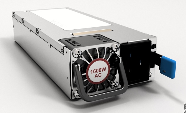
The NCS-57C3-MOD router has 2 PSUs that install into the chassis from the front. The PSUs have a capacity of 1600W and works with 1+1 redundancy. The PSU can be AC to DC or DC to DC type. The PSUs provide 12V primary power to the entire system.

The router supports these PSUs:

  • NC57-1600W-ACFW — 1600W AC power supply module with port-side air intake

  • NC57-1600W-DCFW — 1600W 48VDC power supply module with port-side air intake

Figure 9. NCS-57C3-MOD AC Power Supply Unit

The NCS-57D2-18DD-SYS router has 2 PSUs that install into the chassis from the front. The PSUs have a capacity of 2000W and works with 1+1 redundancy. The PSU can be AC to DC or DC to DC type. The PSUs provide 12V primary power to the entire system.

The router supports the PSUs that are listed in the following table:

Table 5. Supported PSUs

PSU PID

Airflow Direction

PSU2KW-ACPI

Front to Rear

PSU2KW-DCPI

Front to Rear

PSU2KW-ACPE

Rear to Front

PSU2KW-DCPE

Rear to Front

Figure 10. NCS-57D2-18DD-SYS AC Power Supply Unit

Route Processor Card

Route processor cards manage all routing operations on the Cisco NCS-57C3-MOD router.

NC57-MOD-RP2-E

1

USB port

3

Management Ethernet port

2

Console port

4

Recessed reset (ORS) button

Modular Port Adapters

The modular port adapters (MPAs) are supported in the NCS-57C3-MOD and NCS-57C3-MODS-SYS fixed-port routers. Each MPA has a STATUS and ATTN (attention) LED, and each port on the MPA has an adjacent A/L (Active/Link) LED.

To determine which transceivers and cables are supported by these MPAs, see Cisco Transceiver Modules Compatibility Information.


Note


Before replacing an MPA card remove the port-range configurations that are applied on that MPA. If these configurations are not removed, interfaces in the new MPA card are not available.


4-Port 40GE/100GE MPA with QSFP+/QSFP28

The 4-port 40GE/100GE MPA (NC55-MPA-4H-S) provides 4 ports for 4x25GE (via cable breakout), QSFP+ (40Gbps) or QSFP28 (100Gbps) transceivers.

1

STATUS LED

3

QSFP port and Active/Link LED

2

QSFP port and Active/Link LED

4

ATTN LED

2-Port 100GE/200GE with CFP2-DCO

The 2-port 100GE/200GE MPA (NC55-MPA-2TH-S) provides 2 ports for CFP2-DCO transceivers.

1

STATUS LED

3

CFP2-DCO port and Active/Link LED

2

CFP2-DCO port and Active/Link LED

4

ATTN LED

1-port 100GE/200GE with CFP2-DCO + 2-Port 40GE or 100GE with QSFP+/QSFP28

The 1-port 100GE/200GE + 2-Port 40GE/100GE combination MPA (NC55-MPA-1TH2H-S) provides 1 port for CFP2-DCO transceivers and 2 ports for 4x25GE (via cable breakout), QSFP+ (40Gbps) or QSFP28 (100Gbps) transceivers.

1

STATUS LED

3

CFP2-DCO port and Active/Link LED

2

QSFP port and Active/Link LED

4

ATTN LED

12-Port 10GE with SFP+

The 12-port 10GE MPA (NC55-MPA-12T-S) provides 12 ports for SFP+ transceivers.

1

STATUS LED

3

ATTN LED

2

SFP+ ports and LEDs


Note


The NCS-57C3 routers support 12-port 10GE MPA (NC55-MPA-12T-S); however, MPA slots 2 and 3 do not support 1G interfaces. On slot 1, ports 0-3 and 8-11 only support 1G. MACSec is not supported on these 1G interfaces.


4-Port 800GE MPA with QSFP28/QSFP-DD

Table 6. Feature History Table

Hardware

Release Information

Description

NC57-MPA-2D4H-S modular port adapter

Release 7.4.1

This release introduces a 4-port 800GE modular port adapter (NC57-MPA-2D4H-S) that supports QSFP28 and QSFP-DD optical transceivers. This MPA is supported in the NCS-55A2-MOD and NCS-57C3-MOD routers. This is the first modular port adapter to support the QSFP-DD optical transceiver.

The NC57-MPA-2D4H-S modular port adapter supports QSFP28 and QSFP-DD optical transceivers in the following configurations:

The NC57-MPA-2D4H-S modular port adapter supports the following configurations of optical transceivers while operating on NC55-MOD-A-SE-S and NC57-MOD-S line cards.

Transceiver

MPA slot 1

MPA slots 2 and 3

Max bandwidth = 400GE

Note

 
You can use a combination of QDD-2x100GE (Port 0 or Port 2) and QSFP28-100GE (Port 0, 1, 2 or 3) transceivers at the same time, provided the total bandwidth does not exceed 400GE.

Max bandwidth per MPA = 800GE

Note

 
You can use a combination of QDD-400GE (Port 0 or Port 2) and QSFP28-100GE/QDD-2x100GE (Port 0, 1, 2 or 3) transceivers at the same time, provided the total bandwidth does not exceed 800GE.
QSFP28-100GE All ports All ports
QDD-2x100GE

Ports 0 and 2

Note

 
When QDD-2x100GE transceivers are installed in ports 0 and 2, ports 1 and 3 cannot be used.
All ports
QDD-400GE

Port 0

Note

 
When QDD-400GE transceiver is installed in port 0, ports 1, 2, and 3 cannot be used

Ports 0 and 2

Note

 
When QDD-400GE transceivers are installed in ports 0 and 2, ports 1 and 3 cannot be used.
The following are the limitations while using NC57-MPA-2D4H-S on NCS-57C3-MOD/ NCS-57C3-MODS-SYS.
  • While configuring 400G or 2x100G speeds on even ports (0 and 2), you should not have 40G or 4x10G interfaces on odd ports (1 and 3).

  • While configuring 3x100G speeds on even ports (0 and 2), you should not have 40G or 4x10G interfaces on odd ports (1 and 3).

  • In MPA slot 0, you can configure only one 4x100G interface, either in port 0 or port 2.

Figure 11. NC57-MPA-2D4H-S Modular Port Adapter (MPA)

1

STATUS LED

3

Active/Link LED

2

QSFP28/QSFP-DD port and LED

4

ATTN LED

12-Port 10GE/25GE/50GE MPA with SFP+/SFP28/SFP56

Table 7. Feature History Table

Hardware

Release Information

Feature Description

NCS57-MPA-12L-S modular port adapter

Release 7.6.1

A 12-port 600GE modular port adapter that supports SFP+, SPF28, and SFP56 optical transceivers, the NCS57-MPA-12L-S operates in 10GE, 25GE, and 50GE modes.

The following command is modified to add support for the 50GE mode for even-numbered ports (port 4, port 6, port 8, and port 10):

For more information, see the Cisco Network Convergence System 5700 Series: Modular Port Adapters Data Sheet.

The NCS57-MPA-12L-S modular port adapter supports SFP+, SFP28 and SFP56 optical transceivers in these configurations:

Table 8. Supported SFP optical transceiver configurations

Port

MPA Slot-1

MPA Slot-2 and Slot-3

Maximum bandwidth per MPA = 400GE

Maximum bandwidth per MPA = 600GE

0 and 1

  • 10G

  • 25G

  • 50G

  • Combination of 10G, 25G and 50G

  • 10G

  • 25G

  • 50G

  • Combination of 10G and 25G

  • Combination of 25G and 50G

Note


Combination of 10G and 50G or 10G, 25G and 50G is not supported.

2 and 3

4, 5, 6 and 7

  • 10G

  • 25G

  • 50G

  • Combination of 10G, 25G and 50G

Note


50G can be enabled on even-numbered ports using hw-module port-range and the subsequent odd port will be disabled.

8, 9, 10 and 11

Figure 12. NCS57-MPA-12L-S Modular Port Adapter (MPA)

1

STATUS LED

3

ATTN LED

2

SFP56 ports and LEDs

8-Port MPA with SFP+

Table 9. Feature History Table

Hardware

Release Information

Description

NC55-OIP-02 Modular Port Adapter

Release 7.7.1

An 8-port MPA (NC55-OIP-02) that supports SFP+ optical transceivers, this MPA is available for the NC55A2-MOD-S and NC57C3-MOD-SYS routers. It supports the following port mode options:

  • Ethernet

  • FC

  • OTN

  • SDH

  • SONET

The port-mode command is introduced to configure port mode option.

For more information on PLE, see Private Line Emulation over EVPN-VPWS Single Homed section of the L2VPN and Ethernet Services Configuration Guide for Cisco NCS 5500 Series Routers, IOS XR Release 7.7.x.

For more information on the MPA, see the Cisco Network Convergence System 5700 Series: Modular Port Adapters Data Sheet.

The NC55-OIP-02 modular port adapter supports SFP+ optical transceivers. The MPA supports the following port mode options:

  • Ethernet - 1GbE and 10GbE

  • Fiber channel (FC) - 1G, 2G, 4G, 8G, 16G, and 32G

  • Optical Transport Network (OTN) - OTU2 and OTU2e

  • Synchronous Digital Hierarchy (SDH) - STM16 and STM64

  • SONET - OC48 and OC192


Note


The NC55-OIP-02 supports circuit emulation (CEM) and does not support L3 VPN service termination.


The MPA supports the following data rates:

Table 10. Port mode data rate options
Port mode Data rate

1GbE

1.25 Gbps

10GbE

10.3125 Gbps

OC48

2.48832 Gbps

OC192

9.95328 Gbps

OTU2

10.709 Gbps

OTU2e

11.0957 Gbps

STM16

2.48 Gbps

STM64

9.95 Gbps

FC1

1.0625 Gbps

FC2

2.125 Gbps

FC4

4.25 Gbps

FC8

8.5 Gbps

FC16

14.025 Gbps

FC32

28.05 Gbps


Note


Port mode FC32 is supported only on the even ports (Port 0, 2, 4, and 6) of the MPA.


Figure 13. NC55-OIP-02 Modular Port Adapter (MPA)

1

STATUS LED

3

ATTN LED

2

SFP+ port

4

Active/Link LED

1-port 400GbE with CFP2-DCO + 1-Port 400GbE with QSFP-DD MPA

Table 11. Feature History Table

Hardware

Release Information

Feature Description

NCS57-MPA-1FH1D-S Modular Port Adapter

Release 7.8.1

This release introduces NCS57-MPA-1FH1D-S, a 2-port 800GbE modular port adapter with one port supporting QSFP-DD and the other supporting CFP2-DCO optical transceivers.

This MPA is supported in the NCS-57C3-MODS-SYS router and NC57-MOD-S line card.

For more information, see the Cisco Network Convergence System 5700 Series: Modular Port Adapters Data Sheet.

The 2-port 800GbE MPA (NCS57-MPA-1FH1D-S) provides one port for QSFP-DD and one port for CFP2-DCO transceivers. The QSFP-DD port operates in 400GbE mode and supports 4x100G breakout mode, and the CFP2-DCO port operates in 400GbE mode and supports 4x100G, or 3x100G, or 2x100G, or 1x100G breakout modes.

1

STATUS LED

3

CFP2-DCO port and LED

2

QSFP-DD port and LED

4

ATTN LED

Network Interfaces

NCS-57B1

The Cisco NCS-57B1 Router has the following ports:

  • 24 ports of 100G QSFP-DD.

  • 6 ports of 400G QSFP-DD. Applicable for NCS-57B1-6D24-SYS.

  • 5 ports of 400G QSFP-DD. Applicable for NCS-57B1-5DSE-SYS.

In the NCS-57B1-5DSE-SYS and NCS-57B1-6D24-SYS routers, the ports from 0 to 23 are organized into groups of four, known as quad ports: Quad 0 (ports 0-3), Quad 1 (ports 4-7), Quad 2 (ports 8-11), Quad 3 (ports 12-15), Quad 4 (ports 16-19), and Quad 5 (ports 20-23) to support various SFP/QSFP and breakout configurations.

Each quad contains two pairs of ports. For example, ports 0-1 make up pair 1, and ports 2-3 make up pair 2 in Quad 0.

To adjust the speed of a port in a pair, you must first disable the other port in the pair, then change the speed as required, and finally re-enable both ports.

For instance, in Quad 4 (ports 16-19), SFPs need to be inserted in pairs such as 16-17 and 18-19. To change the speed of port 17 while port 16 is active, you must first disable port 16 before inserting the optics into port 17.


Note


  • In all quads (Quad 0: 0-3, Quad 1: 4-7, ..., Quad 5: 20-23), a 4x25 breakout cannot coexist with either 40G native mode or 4x10 breakout mode.

  • Additionally, the interface speed on Quad 0 must be consistent across all ports at any given time.


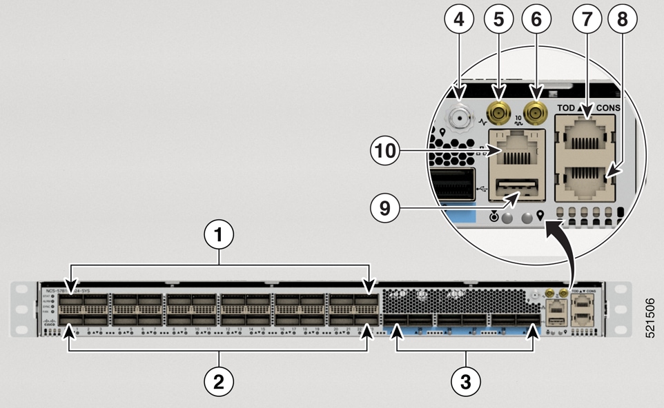
Figure 14. NCS-57B1-5DSE-SYS—Front View

1

12 QSFP-DD ZR ports

6

10MHz port

2

12x100G QSFP-DD ports

Note


Only even ports support QSFP-DD 100G-ZR

7

Time of Day (ToD) port

3

5x400G QSFP-DD ports

8

Console port

4

GNSS

9

USB port

5

1 PPS port

10 Management Ethernet port
Figure 15. NCS-57B1-6D24-SYS—Front View

1

12 QSFP-DD ZR ports

6

10MHz port

2

12x100G QSFP-DD ports

Note


Only even ports support QSFP-DD 100G-ZR

7

Time of Day (ToD) port

3

6x400G QSFP-DD ports

8

Console port

4

GNSS

9

USB port

5

1 PPS port

10 Management Ethernet port

Note


Some of the ports are color coded in the chassis for ease of access:

  • The ports from 0 through 23 have no color.

  • The ports from 24 onwards are colored in blue.


The rear view of both the routers is same.

Figure 16. NCS-57B1-6D24-SYS and NCS-57B1-5DSE-SYS—Rear View

1 and 3

PSU-0 and PSU-1

2

Fan Trays

4,5,6,7,8, and 9

Six Fan Trays: FT0, FT1, FT2, FT3, FT4, and FT5

NCS-57C1

The Cisco NCS-57C1 router has the following ports on the front panel:

  • 4 ports of 400G QSFP-DD

  • 2 ports of 4x100G QSFP-DD

  • 16 ports of 50G SFP+ (also supports traffic speed of 10G/25G/1G)

  • 32 ports of 25G SFP+ (also supports traffic speed of 10G/1G)

  • Console port

  • Management port

Figure 17. NCS-57C1—Front View

1

Port 0, 2, 4, and 5. 400G QSFP-DD ports.

2

Port 1 and 3. 4x100G QSFP-DD ports.

3

Ports 6 through port 21. Supports 50/25/10/1G traffic speed.

4

Ports 22 through port 53. Supports 25/10/1G traffic speed.

5

Console port.

6

Management port.


Note


In the NCS-57C1 routers, there are additional thermal vent perforations next to the port status LEDs. These perforations are meant to provide additional air flow for cooling the chassis. The LED status of a port can be viewed from these perforations as well.


The Cisco NCS-57C1 router has PSUs, fan modules, and network timing interfaces on the rear side:

Figure 18. NCS-57C1—Rear View

1 and 2

PSU-0 and PSU-1

3

Fan Trays

4

Time Of Day (TOD) port. RS422 format as input.

5

Building Integrated Timing Supply (BITS) port.

Note


The BITS port is not enabled in Cisco IOS XR Release 7.5.2.

6

1 PPS port

7

GNSS port

8

USB port

9

USB console. This port is used as an alternative for the front panel console port.

10

10 MHz port

NCS-57C3-MOD

The Cisco NCS-57C3-MOD router has the following ports:

  • 48 ports of 25G SFP28

  • 4 ports (NCS-57C3-MOD-SE-S) or 8 ports (NCS 57C3-MOD-S) of 100G QSFP28

  • MACsec supported on the following SFP28 ports:

    • NCS 57C3-MOD-S: ports 0-3, 40-55

    • NCS-57C3-MOD-SE-S: ports 0-7, 36-51

Figure 19. NCS-57C3-MOD-SE-S—Front View

1

48 ports of 25G SFP28

6

PPS port

2

4 ports (NCS-57C3-MOD-SE-S) or 8 ports (NCS 57C3-MOD-S) of 100G QSFP28

7

10 MHz port

3

USB ports

8

GNSS port

4

Console ports

9

Time of Day (ToD) port

5

Management Ethernet ports

The rear view of both the chassis is same.

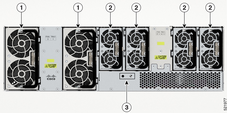
Figure 20. NCS 57C3-MOD—Rear View

1

Fan tray assembly with 2x60mm fans (NC57-C3-FAN2-FW)

2

Fan tray assembly with 2x40mm fans (NC57-C3-FAN1-FW)

3

Grounding pad

NCS-57D2-18DD-SYS

The Cisco NCS-57D2-18DD-SYS router has the following ports on the front panel:

  • 66 QSFP-DD ports

  • Management port

  • Cosole port

  • Network timing interfaces

  • GNSS port

  • USB port

Figure 21. NCS-57D2-18DD-SYS Front View

1

Mini coax connector for 1 PPS, input, and output.

5

USB port

2

Mini coax connector for 10MHz, input, and output.

6

66 QSFP-DD ports

3

GNSS port

7

Time of Day (ToD) port

4

Management Ethernet port

8

Console port

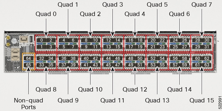
The NCS-57D2-18DD-SYS router ports are divided as below:

  • 16 quads (group of 4 ports)

  • 2 non-quad ports

These 16 quads and 2 non-quad ports (a total of 66 ports) provide 18x400GbE or 66x100GbE configuration options.
Figure 22. Quad and Non-quad Ports

All 16 quads are identical and provide flexible port configuration.

Consider one quad group with ports labelled as P0, P1, P2, and P3. This sequence of port numbering (P0, P1, P2, and P3) and the behavior of ports is the same for each quad group:

Figure 23. Single Quad Group - P0, P1, P2, and P3

A quad group can support up to 400GbE total traffic.

The following table outlines the supported port configuration for various optics on a quad group in the NCS-57D2-18DD-SYS router:

Table 12. Supported Port Configuration
Front Panel Configuration Supported Front Panel Ports per Quad
Number of ports x Port Configuration Active Port Disabled Port

1x400GbE

P0 – 400GbE

P1, P2, and P3

4x100GbE

P0 – 100GbE

P1– 100GbE

P2 – 100GbE

P3 – 100GbE

NA

4x40GbE

P0 – 40GbE

P1 – 40GbE

P2 – 40GbE

P3 – 40GbE

NA

4x25GbE (breakout)

P0 – 25GbE

P3 – 25GbE

P1 and P2

4x10GbE (breakout)

P0 – 10GbE

P3 – 10GbE

P1 and P2


Note


QDD-400G-ZRP optical modules are supported on P0 and P3 of the quad group and both non-quad ports (port 64 and 65). Refer to the tables below for different operating mode combinations.

QDD-400G-ZR-S optical modules are supported only on P0 quad group and both non-quad ports (port 64 and 65).


The following tables provide the supported combinations of QDD-400G-ZRP and other optical modules. These tables contain information of optical modules supported in the remaining ports of the quad group, while the QDD-400G-ZRP module is used in P0 and configured in the muxponder mode. Also, when QDD-400G-ZRP is configured in 1x100GbE or 2x100GbE muxponder modes, they can be used on both P0 and P3 quad ports; however the remaining P1 and P2 quad ports are disabled.

Table 13. Supported Combinations of QDD-400G-ZR-S/QDD-400G-ZRP Optical Modules
Quad Port 1

QDD-400G-ZR-S/QDD-400G-ZRP

QDD-400G-ZRP

QDD-400G-ZRP (P0 and P3)

N+0

400GbE/4x100GbE

3x100GbE

2x100GbE/1x100GbE

N+1

Disabled

Disabled

Disabled

N+2

Disabled

Disabled

Disabled

N+3

Disabled

Disabled

2x100GbE/1x100GbE

1 N = Quad Number x 4. The Quad Number can range from 0 to 15.
Table 14. Supported Combinations of QDD-400G-ZRP (2x100GbE Muxponder Mode) on N+0 and other Optical Modules
Quad Port 2

QDD-400G-ZRP

QDD-400G-ZRP

N+0

2x100GbE

2x100GbE

N+1

40GbE/100GbE

Disabled

N+2

Disabled

Disabled

N+3

40GbE/100GbE

4x10GbE/4x25GbE

2 N = Quad Number x 4. The Quad Number can range from 0 to 15.
Table 15. Supported Combinations of QDD-400G-ZRP (1x100GbE Muxponder Mode) on N+0 and other Optical Modules
Quad Port 3

QDD-400G-ZRP

QDD-400G-ZRP

QDD-400G-ZRP

N+0

1x100GbE

1x100GbE

1x100GbE

N+1

40GbE/100GbE

Disabled

Disabled

N+2

40GbE/100GbE

100GbE

40GbE/100GGbE

N+3

40GbE/100GbE

4x25GbE

4x10GbE

3 N = Quad Number x 4. The Quad Number can range from 0 to 15.

The Cisco NCS-57D2-18DD-SYS router has PSUs and fan modules on the rear side:

Figure 24. NCS-57D2-18DD-SYS—Rear View

1

PSUs

2

Fan modules (4)

Specification

For information on physical specification, temperature, Route Processor, and other details for all variants, see Cisco NCS 5700 chassis specification of the Cisco Network Convergence System 5700 Router Data Sheet.

Network Timing Interfaces

For location of network timing interfaces on the routers, see Network Interfaces.

Clock interfaces are external connectors for connecting timing signals, such as, GPS and Building Integrated Timing Supply (BITS).

GPS

The router can receive 1PPS, 10 MHz, and ToD signals from an external clocking and timing source. The three inputs are combined as a Sync-2 interface to form the external timing source or the GPS input.

The GPS connector details present on router are:

  • ToD—RS422 format as input. ToD format includes both NTP and IEEE 1588-2008 time formats.

  • 1PPS—1.0/2.3 DIN connector as input

  • 10MHz—1.0/2.3 DIN connector as input

1PPS input or output and ToD input or output—This shielded RJ-45 interface is used for input or output of time-of-day (ToD) and 1PPS pulses. ToD format includes both NTP and IEEE 1588-2008 time formats.

The same RS422 pins for 1PPS and TOD are shared between input and output directions. The direction for each can be independently configurable through software.

Use an SMB connector of type DIN 1.0/2.3 for the following:

  • GPS 10Mhz input and output—10MHz input for GPS Synchronization.

  • GPS 1 PPS input and output—1 PPS input for GPS Synchronization.

BITS

The router supports receiving (Rx) and transmitting (Tx) of frequency via BITS interface. To receive and transmit BITS signals, configuration is done under the clock-interface sync 0 on the route processor (RP). BITS port is present on the rear side of NCS-57C1 router.


Note


On a 1GE interface for NCS-57C1 router, the jitter experienced with SyncE can be beyond the G.8262 tolerance specification.


GNSS

GNSS module has an in-built ESD protection on all pins, including the RF-input pin. However, additional surge protection is required if an outdoor antenna is being connected. The Lightning Protector must support a low clamping voltage (less than 600V).

GNSS Module RF Input Requirements

  • The GNSS module requires an active GPS/GNSS antenna with built-in Low-Noise Amplifier (LNA) for optimal performance. The antenna LNA amplifies the received satellite signals for two purposes:
    • Compensation of losses on the cable

    • Lifting the signal amplitude in the suitable range for the receiver frontend

    The Amplification required is 22dB gain + cable/connector loss + Splitter signal loss.

    The recommended range of LNA gain (LNA gain minus all cable and connector or splitter losses) at the connector of the receiver module is 22dB to 30dB with a minimum of 20dB and a maximum of 35dB.

  • GNSS module provides 5V to the active antenna through the same RF input.

  • Actual supply voltage at the antenna LNA input depends on the current drawn by the antenna . Antennas with high current consumption, leads to more drop, hence supply voltage at the RF-connector may drop too low to provide sufficient power to the antenna LNA. In that case, we recommend to use either antennas with lower operating current or with wider supply voltage range (3V to 5.5V)

  • Recommended maximum current drawn from GNSS module is 55mA. The system triggers short alarm when antenna LNA consumes more than100mA. Open alarm triggered if antenna consume very less current (less than 4 - 8mA) or the cable is open.

  • Surge requirement:
    • GNSS modules have built-in ESD protections on all pins, including the RF-input pin. However, additional surge protection may be required if rooftop antennas are being connected, to meet the regulations and standards for lightning protection in the countries where the end-product is installed.

    • A lightning protection must be mounted at the place where the antenna cable enters the building. The primary lightning protection must be capable of conducting all potentially dangerous electrical energy to PE (Protective Earth).

    • Surge arrestors should support DC-pass and suitable for the GPS frequency range (1.575GHz) with low attenuation.

  • Antenna Sky visibility:
    • GNSS signals can only be received on a direct line of sight between antenna and satellite. There should not be any obstacle between the antenna and the open sky. For proper timing, minimum of four satellites should be locked with C/No value greater than 35.

      Note


      The antenna terminal should be earthed at the building entrance in accordance with the ANSI/NFPA 70, the National Electrical Code (NEC), in particular Section 820.93, Grounding of Outer Conductive Shield of a Coaxial Cable.


    • Use a passive splitter if more than one GNSS modules are fed from a single antenna.

      Note


      The splitter should have all the RF ports capable of DC-pass, if the antenna needs to feed power from GNSS module.


Console

The RS232 console port provides transmission (Tx), reception (Rx), and ground (Gnd).

Online Insertion and Removal

The router supports OIR for optical modules, power supplies, and fan modules and trays.

The router supports the following OIR operations:

  • When an optical module is removed, there is no effect on traffic flowing on other ports.

  • When an optical module is installed, the system initializes that port for operation that is based on the current configuration. If the inserted optical module is incompatible with the current configuration for that port, the port does not become operational until the configuration is updated.

  • With both power supplies installed and active, the load is shared between them.

    When a power supply is removed, not working (failure), or the input cable is removed, the remaining power supply takes the entire load without disruption.

  • There are six fan modules for the NCS 57B1 chassis, five fan modules for the NCS 57C1 chassis, and six fan trays for the NCS 57C3-MOD chassis. Each module or fan tray has two fan units.