Configuring High Availability
This chapter describes how to configure high availability, and describes the switchover processes.
About High Availability
Process restartability provides the high availability functionality in Cisco MDS 9000 Family switches. This process ensures that process-level failures do not cause system-level failures. It also restarts the failed processes automatically. This process is able to restore its state prior to the failure and continues executing from the failure point going forward.
An HA switchover has the following characteristics:
-
It is stateful (nondisruptive) because control traffic is not impacted.
-
It does not disrupt data traffic because the switching modules are not impacted.
-
Switching modules are not reset.
 Note |
Switchover is not allowed if auto-copy is in progress. |
Switchover Processes
Switchovers occur by one of the following two processes:
-
The active supervisor module fails and the standby supervisor module automatically takes over.
-
You manually initiate a switchover from an active supervisor module to a standby supervisor module.
Once a switchover process has started another switchover process cannot be started on the same switch until a stable standby supervisor module is available.
 Caution |
If the standby supervisor module is not in a stable state (ha-standby), a switchover is not performed. |
This section includes the following topics:
Synchronizing Supervisor Modules
The running image is automatically synchronized in the standby supervisor module by the active supervisor module. The boot variables are synchronized during this process.
The standby supervisor module automatically synchronizes its image with the running image on the active supervisor module.
Note |
The image a supervisor module is booted up from cannot be deleted from bootflash. This is to ensure that the new standby supervisor module ia able to synchronize during the process. |
Manual Switchover Guidelines
Be aware of the following guidelines when performing a manual switchover:
-
When you manually initiate a switchover, system messages indicate the presence of two supervisor modules.
-
A switchover can only be performed when two supervisor modules are functioning in the switch.
-
The modules in the chassis are functioning as designed.
Manually Initiating a Switchover
To perform a switchover using Device Manager, follow these steps:
Procedure
| Step 1 |
Ensure that an HA switchover is possible by selecting Physical > Modules to verify the presence of multiple modules. You see the screen shown in Figure 1. 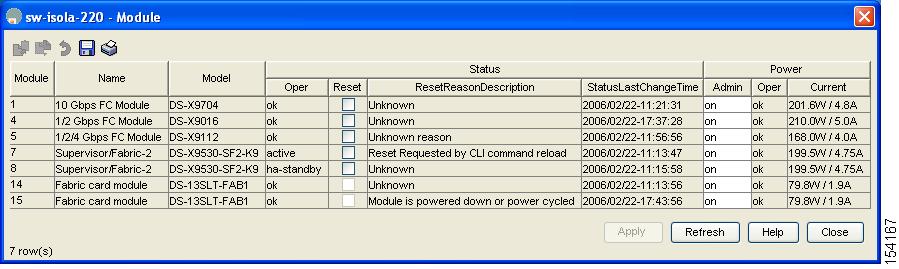
|
| Step 2 |
In the main Device Manager screen, select Admin > Reset Switch . 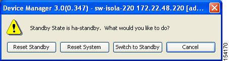
|
| Step 3 |
Click Switch to Standby . |
Copying Boot Variable Images to the Standby Supervisor Module
You can copy the boot variable images that are in the active supervisor module (but not in the standby supervisor module) to the standby supervisor module. Only those KICKSTART and SYSTEM boot variables that are set for the standby supervisor module can be copied. For module (line card) images, all boot variables are copied to the corresponding standby locations (bootflash: or slot0:) if not already present.
Displaying HA Status Information
The following conditions identify when automatic synchronization is possible:
-
If the internal state of one supervisor module is Active with HA standby and the other supervisor module is HA standby, the switch is operationally HA and can do automatic synchronization.
-
If the internal state of one of the supervisor modules is none, the switch cannot do automatic synchronization.
Table 1 lists the possible values for the redundancy states.
|
State |
Description |
||
|---|---|---|---|
|
Not present |
The supervisor module is not present or is not plugged into the chassis. |
||
|
Initializing |
The diagnostics have passed and the configuration is being downloaded. |
||
|
Active |
The active supervisor module and the switch is ready to be configured. |
||
|
Standby |
A switchover is possible. |
||
|
Failed |
The switch detects a supervisor module failure on initialization and automatically attempts to power-cycle the module three (3) times. After the third attempt it continues to display a failed state.
|
||
|
Offline |
The supervisor module is intentionally shut down for debugging purposes. |
||
|
At BIOS |
The switch has established connection with the supervisor and the supervisor module is performing diagnostics. |
||
|
Unknown |
The switch is in an invalid state. If it persists, call TAC. |
Table 2 lists the possible values for the supervisor module states.
|
State |
Description |
|---|---|
|
Active |
The active supervisor module in the switch is ready to be configured. |
|
HA standby |
A switchover is possible. |
|
Offline |
The switch is intentionally shut down for debugging purposes. |
|
Unknown |
The switch is in an invalid state and requires a support call to TAC. |
Table 3 lists the possible values for the internal redundancy states.
|
State |
Description |
|---|---|
|
HA standby |
The HA switchover mechanism in the standby supervisor module is enabled (see the Synchronizing Supervisor Modules). |
|
Active with no standby |
A switchover is not possible. |
|
Active with HA standby |
The active supervisor module in the switch is ready to be configured. The standby supervisor module is in the HA-standby state. |
|
Shutting down |
The switch is being shut down. |
|
HA switchover in progress |
The switch is in the process of changing over to the HA switchover mechanism. |
|
Offline |
The switch is intentionally shut down for debugging purposes. |
|
HA synchronization in progress |
The standby supervisor module is in the process of synchronizing its state with the active supervisor modules. |
|
Standby (failed) |
The standby supervisor module is not functioning. |
|
Active with failed standby |
The active supervisor module and the second supervisor module is present but is not functioning. |
|
Other |
The switch is in a transient state. If it persists, call TAC. |
 Feedback