Configuring IPv4 and IPv6 Access Control Lists
Cisco MDS 9000 Family switches can route IP version 4 (IPv4) traffic between Ethernet and Fibre Channel interfaces. The IP static routing feature routes traffic between VSANs. To do so, each VSAN must be in a different IPv4 subnetwork. Each Cisco MDS 9000 Family switch provides the following services for network management systems (NMS):
- IP forwarding on the out-of-band Ethernet interface (mgmt0) on the front panel of the supervisor modules.
- IP forwarding on the in-band Fibre Channel interface using the IP over Fibre Channel (IPFC) function—IPFC specifies how IP frames can be transported over Fibre Channel using encapsulation techniques. IP frames are encapsulated into Fibre Channel frames so NMS information can cross the Fibre Channel network without using an overlay Ethernet network.
- IP routing (default routing and static routing)—If your configuration does not need an external router, you can configure a default route using static routing.
Switches are compliant with RFC 2338 standards for Virtual Router Redundancy Protocol (VRRP) features. VRRP is a restartable application that provides a redundant, alternate path to the gateway switch.
IPv4 Access Control Lists (IPv4-ACLs and IPv6-ACLs) provide basic network security to all switches in the Cisco MDS 9000 Family. IPv4-ACLs and IPv6-ACLs restrict IP-related traffic based on the configured IP filters. A filter contains the rules to match an IP packet, and if the packet matches, the rule also stipulates if the packet should be permitted or denied.
Each switch in the Cisco MDS 9000 Family can have a maximum total of 128 IPv4-ACLs or 128 IPv6-ACLs and each IPv4-ACL or IPv6-ACL can have a maximum of 256 filters.
This chapter includes the following topics:
Information About IPv4 and IPv6 Access Control Lists
Cisco MDS 9000 Family switches can route IP version 4 (IPv4) traffic between Ethernet and Fibre Channel interfaces. The IP static routing feature routes traffic between VSANs. To do so, each VSAN must be in a different IPv4 subnetwork. Each Cisco MDS 9000 Family switch provides the following services for network management systems (NMS):
- IP forwarding on the out-of-band Ethernet interface (mgmt0) on the front panel of the supervisor modules.
- IP forwarding on the in-band Fibre Channel interface using the IP over Fibre Channel (IPFC) function—IPFC specifies how IP frames can be transported over Fibre Channel using encapsulation techniques. IP frames are encapsulated into Fibre Channel frames so NMS information can cross the Fibre Channel network without using an overlay Ethernet network.
- IP routing (default routing and static routing)—If your configuration does not need an external router, you can configure a default route using static routing.
IPv4 Access Control Lists (IPv4-ACLs and IPv6-ACLs) provide basic network security to all switches in the Cisco MDS 9000 Family. IPv4-ACLs and IPv6-ACLs restrict IP-related traffic based on the configured IP filters. A filter contains the rules to match an IP packet, and if the packet matches, the rule also stipulates if the packet should be permitted or denied.
Each switch in the Cisco MDS 9000 Family can have a maximum total of 128 IPv4-ACLs or 128 IPv6-ACLs and each IPv4-ACL or IPv6-ACL can have a maximum of 256 filters.
This section contains the following topics:
About Filter Contents
An IP filter contains rules for matching an IP packet based on the protocol, address, port, ICMP type, and type of service (ToS).
Protocol Information
The protocol information is required in each filter. It identifies the name or number of an IP protocol. You can specify the IP protocol in one of two ways:
- Specify an integer ranging from 0 to 255. This number represents the IP protocol.
- Specify the name of a protocol including, but not restricted to, Internet Protocol (IP), Transmission Control Protocol (TCP), User Datagram Protocol (UDP), and Internet Control Message Protocol (ICMP).
 Note |
When configuring IPv4-ACLs or IPv6-ACLs on Gigabit Ethernet interfaces, only use the TCP or ICMP options. |
Address Information
The address information is required in each filter. It identifies the following details:
- Source—The address of the network or host from which the packet is being sent.
- Source-wildcard—The wildcard bits applied to the source.
- Destination—The number of the network or host to which the packet is being sent.
- Destination-wildcard—The wildcard bits applied to the destination.
Specify the source and source-wildcard or the destination and destination-wildcard in one of two ways:
-
Using the 32-bit quantity in four-part, dotted decimal format (10.1.1.2/0.0.0.0 is the same as host 10.1.1.2).
- Each wildcard bit set to zero indicates that the corresponding bit position in the packet's IPv4 address must exactly match the bit value in the corresponding bit position in the source.
- Each wildcard bit set to one indicates that both a zero bit and a one bit in the corresponding position of the packet's IPv4 or IPv6 address will be considered a match to this access list entry. Place ones in the bit positions you want to ignore. For example, 0.0.255.255 requires an exact match of only the first 16 bits of the source. Wildcard bits set to one do not need to be contiguous in the source-wildcard. For example, a source-wildcard of 0.255.0.64 would be valid.
- Using the any option as an abbreviation for a source and source-wildcard or destination and destination-wildcard (0.0.0.0/255.255.255.255)
Port Information
The port information is optional. To compare the source and destination ports, use the eq (equal) option, the gt (greater than) option, the lt (less than) option, or the range (range of ports) option. You can specify the port information in one of two ways:
- Specify the number of the port. Port numbers range from 0 to 65535. Table 1 displays the port numbers recognized by the Cisco NX-OS software for associated TCP and UDP ports.
-
Specify the name of a TCP or UDP port as follows:
- TCP port names can only be used when filtering TCP.
- UDP port names can only be used when filtering UDP.
|
Protocol |
Port |
Number |
|---|---|---|
|
UDP |
dns |
53 |
|
tftp |
69 |
|
|
ntp |
123 |
|
|
radius accounting |
1646 or 1813 |
|
|
radius authentication |
1645 or 1812 |
|
|
snmp |
161 |
|
|
snmp-trap |
162 |
|
|
syslog |
514 |
|
|
TCP1 |
ftp |
20 |
|
ftp-data |
21 |
|
|
ssh |
22 |
|
|
telnet |
23 |
|
|
smtp |
25 |
|
|
tasacs-ds |
65 |
|
|
www |
80 |
|
|
sftp |
115 |
|
|
http |
143 |
|
|
wbem-http |
5988 |
|
|
wbem-https |
5989 |
ICMP Information
IP packets can be filtered based on the following optional ICMP conditions:
- icmp-type—The ICMP message type is a number from 0 to 255.
- icmp-code—The ICMP message code is a number from 0 to 255.
Table 1 displays the value for each ICMP type.
|
ICMP Type2 |
Code |
|---|---|
|
echo |
8 |
|
echo-reply |
0 |
|
destination unreachable |
3 |
|
traceroute |
30 |
|
time exceeded |
11 |
ToS Information
IP packets can be filtered based on the following optional ToS conditions:
- ToS level—The level is specified by a number from 0 to 15.
- ToS name—The name can be max-reliability, max-throughput, min-delay, min-monetary-cost, and normal.
Guidelines and Limitations
Follow these guidelines when configuring IPv4-ACLs or IPv6-ACLs in any switch or director in the Cisco MDS 9000 Family:
-
You can apply IPv4-ACLs or IPv6-ACLs to VSAN interfaces, the management interface, Gigabit Ethernet interfaces on IPS modules and MPS-14/2 modules, and Ethernet PortChannel interfaces.
 Tip |
If IPv4-ACLs or IPv6-ACLs are already configured in a Gigabit Ethernet interface, you cannot add this interface to an Ethernet PortChannel group. See the Cisco MDS 9000 Family NX-OS IP Services Configuration Guide IP Services Configuration Guide, Cisco DCNM for SAN for guidelines on configuring IPv4-ACLs. |
 Caution |
Do not apply IPv4-ACLs or IPv6-ACLs to only one member of a PortChannel group. Apply IPv4-ACLs or IPv6-ACLs to the entire channel group. |
-
Configure the order of conditions accurately. As the IPv4-ACL or the IPv6-ACL filters are sequentially applied to the IP flows, only the first match determines the action taken. Subsequent matches are not considered. Be sure to configure the most important condition first. If no conditions match, the software drops the packet.
-
Configure explicit deny on the IP Storage Gigabit Ethernet ports to apply IP ACLs because implicit deny does not take effect on these ports.
Configuring IPv4-ACLs or IPv6-ACLs
This section contains the following topics:
Creating IPv4-ACLs or IPv6-ACLs
Traffic coming into the switch is compared to IPv4-ACL or IPv6-ACL filters based on the order that the filters occur in the switch. New filters are added to the end of the IPv4-ACL or the IPv6-ACL. The switch keeps looking until it has a match. If no matches are found when the switch reaches the end of the filter, the traffic is denied. For this reason, you should have the frequently hit filters at the top of the filter. There is an implied deny for traffic that is not permitted. A single-entry IPv4-ACL or IPv6-ACL with only one deny entry has the effect of denying all traffic.
To configure an IPv4-ACL or an IPv6-ACL, follow these steps:
-
Create an IPv4-ACL or an IPv6-ACL by specifying a filter name and one or more access condition(s). Filters require the source and destination address to match a condition. Use optional keywords to configure finer granularity.
Note
The filter entries are executed in sequential order. You can only add the entries to the end of the list. Take care to add the entries in the correct order.
-
Apply the access filter to specified interfaces.
To create an ordered list of IP filters in a named IPv4-ACL or IPv6-ACL profile using the IPv4-ACL Wizard, follow these steps:
Procedure
| Step 1 |
Click the IP ACL Wizard icon from the DCNM-SAN toolbar. You see the IP ACL Wizard.
|
||
| Step 2 |
Enter a name for the IP-ACL. If you are creating an IPv6-ACL, check the IPv6 check box. |
||
| Step 3 |
Click Add to add a new rule to this IP-ACL. You see a new rule in the table with default values. |
||
| Step 4 |
Modify the Source IP and Source Mask as necessary for your filter.
|
||
| Step 5 |
Choose the appropriate filter type from the Application drop-down list. |
||
| Step 6 |
Choose permit or deny from the Action drop-down list. |
||
| Step 7 |
Repeat Step 3 through Step 6 for additional IP filters. |
||
| Step 8 |
Click Up or Down to order the filters in this IP-ACL.
|
||
| Step 9 |
Click Next.
|
||
| Step 10 |
Uncheck any switches that you do not want to apply this IP-ACL. |
||
| Step 11 |
Select the Interface you want to apply this IP-ACL. |
||
| Step 12 |
Click Finish to create this IP-ACL and apply it to the selected switches. |

Creating IPv4-ACLs or IPv6-ACLs
To add entries to an existing IPv4-ACL or an IPv6-ACL using Device Manager, follow these steps:
Procedure
| Step 1 |
Choose Security > IP ACL . |
||
| Step 2 |
Click Create to create an IP-ACL profile. You see the Create IP ACL Profiles dialog box. Enter an IP-ACL profile name. |
||
| Step 3 |
Click Create and then click Close . This creates a new IP-ACL profile. |
||
| Step 4 |
Click the IP-ACL you created and click Rules . After you create an IPv4-ACL or an IPv6-ACL, you can add subsequent IP filters at the end of the IPv4-ACL or the IPv6-ACL if you are using Device Manager. DCNM-SAN allows you to reorder existing rules for a profile. You cannot insert filters in the middle of an IPv4-ACL or an IPv6-ACL. Each configured entry is automatically added to the end of a IPv4-ACL or an IPv6-ACL. |
||
| Step 5 |
Click Create to create an IP filter. |
||
| Step 6 |
Choose either permit or deny for the Action and set the IP Number in the Protocol field. The drop-down menu provides common filtered protocols. |
||
| Step 7 |
Set the source IP address you want this filter to match against and the wildcard mask, or check the any check box to match this filter against any IP address. This creates an IP filter that will check the source IP address of frames.
|
||
| Step 8 |
Set the transport layer source port range if the protocol chosen is TCP or UDP. |
||
| Step 9 |
Repeat Step 7 and Step 8 for the destination IP address and port range. This creates an IP filter that will check the destination IP address of frames. |
||
| Step 10 |
Set the ToS, ICMPType, and ICMPCode fields as appropriate. |
||
| Step 11 |
Check the TCPEstablished check box if you want to match TCP connections with ACK,FIN,PSH,RST,SYN or URG control bits set. |
||
| Step 12 |
Check the LogEnabled check box if you want to log all frames that match this IP filter. |
||
| Step 13 |
Click Create to create this IP filter and add it to your IP-ACL. |
Deleting IP-ACLs
Before you begin
You must delete the association between the IP-ACL and interfaces before deleting the IP-ACL.
To delete an IP-ACL, follow these steps:
Procedure
| Step 1 |
Expand Switches > Security, and then select IP ACL from the Physical Attributes pane. You see the IP-ACL configuration in the Information pane. |
| Step 2 |
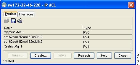
Click the Profiles tab. You see a list of switches, ACLs, and profile names. |
| Step 3 |
Select the row you want to delete. To delete multiple rows, hold down the Shift key while selecting rows. |
| Step 4 |
Click Delete Row . The IP-ACLs are deleted. |
Reading the IP-ACL Log Dump
Use the LogEnabled check box option during IP filter creation to log information about packets that match this filter. The log output displays the ACL number, permit or deny status, and port information.
Use the log-deny option at the end of a filter condition to log information about packets that match dropped entries. The log output displays the ACL number, permit or deny status, and port information.
Note |
To capture these messages in a logging destination, you must configure severity level 7 for the kernel and ipacl facilities and severity level 7 for the logging destination: logfile, monitor or console. For example: switch# config t switch(config)# logging level kernel 7 switch(config)# logging level ipacl 7 switch(config)# logging logfile message 7 |
For the input ACL, the log displays the raw MAC information. The keyword “MAC=” does not refer to showing an Ethernet MAC frame with MAC address information. It refers to the Layer 2 MAC-layer information dumped to the log. For the output ACL, the raw Layer 2 information is not logged.
The following example is an input ACL log dump:
Jul 17 20:38:44 excal-2
%KERN-7-SYSTEM_MSG:
%IPACL-7-DENY:IN=vsan1 OUT= MAC=10:00:00:05:30:00:47:df:10:00:00:05:30:00:8a:1f:aa:aa:03:00:00:00:08:00:45:00:00:54:00:00:40:00:40:01:0e:86:0b:
0b:0b:0c:0b:0b:0b:02:08:00:ff:9c:01:15:05:00:6f:09:17:3f:80:02:01:00:08:09:0a:0b:0c:0d:0e:0f:10:11:12:13:14:15:16:17:18:19:1a:1b:1c:1d:1e:1f:20:
21:22:23:24:25:26:27:28:29:2a:2b SRC=11.11.11.12 DST=11.11.11.2 LEN=84 TOS=0x00 PREC=0x00 TTL=64 ID=0 DF PROTO=ICMP TYPE=8 CODE=0 ID=277 SEQ=1280
The following example is an output ACL log dump:
Jul 17 20:38:44 excal-2
%KERN-7-SYSTEM_MSG:
%IPACL-7-DENY:IN= OUT=vsan1 SRC=11.11.11.2 DST=11.11.11.12 LEN=84 TOS=0x00 PREC=0x00 TTL=255 ID=38095 PROTO=ICMP TYPE=0 CODE=0 ID=277 SEQ=1280
Applying an IP-ACL to an Interface
You can define IP-ACLs without applying them. However, the IP-ACLs will have no effect until they are applied to an interface on the switch. You can apply IP-ACLs to VSAN interfaces, the management interface, Gigabit Ethernet interfaces on IPS modules and MPS-14/2 modules, and Ethernet PortChannel interfaces.
Tip |
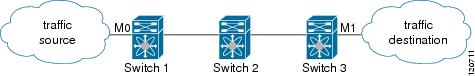
Apply the IP-ACL on the interface closest to the source of the traffic. |
When you are trying to block traffic from source to destination, you can apply an inbound IPv4-ACL to M0 on Switch 1 instead of an outbound filter to M1 on Switch 3.
The access-group option controls access to an interface. Each interface can only be associated with one IP-ACL per direction. The ingress direction can have a different IP-ACL than the egress direction. The IP-ACL becomes active when applied to the interface.
Tip |
Create all conditions in an IP-ACL before applying it to the interface. |
Caution |
If you apply an IP-ACL to an interface before creating it, all packets in that interface are dropped because the IP-ACL is empty. |
The terms in, out, source , and destination are used as referenced by the switch:
- In—Traffic that arrives at the interface and goes through the switch; the source is where it transmitted from and the destination is where it is transmitted to (on the other side of the router).
Tip |
The IP-ACL applied to the interface for the ingress traffic affects both local and remote traffic. |
- Out—Traffic that has already been through the switch and is leaving the interface; the source is where it transmitted from and the destination is where it is transmitted to.
Tip |
The IP-ACL applied to the interface for the egress traffic only affects local traffic. |
Applying an IP-ACL to mgmt0
A system default ACL called mgmt0 exists on the mgmt0 interface. This ACL is not visible to the user, so mgmt0 is a reserved ACL name that cannot be used. The mgmt0 ACL blocks most ports and only allows access to required ports in compliance to accepted security policies.
To apply an IP-ACL to an interface, follow these steps:
Procedure
| Step 1 |
Expand Switches > Security , and then select IP ACL in the Physical Attributes pane. You see the IP-ACL configuration in the Information pane. |
||
| Step 2 |
Click the Interfaces tab. You see a list of interfaces and associated IP-ACLs. |
||
| Step 3 |
Click Create Row . |
||
| Step 4 |
( Optional) Remove the switches you do not want to include in the IP-ACL by unchecking the check boxes next to the switch addresses. Set the interface you want associated with an IPv4-ACL or IPv6-ACL in the Interface field. |
||
| Step 5 |
Choose a ProfileDirection (either inbound or outbound ). |
||
| Step 6 |
Enter the IP-ACL name in the Profile Name field.
|
||
| Step 7 |
Click Create to associate the IP-ACL. You see the newly associated access list in the list of IP-ACLs. |
Configuration Examples for IP-ACL
To define an IP-ACL that restricts management access using Device Manager, follow these steps:
Procedure
| Step 1 |
Choose Security > IP ACL . You see the IP-ACL dialog box. |
| Step 2 |
Click Create to create an IP-ACL. You see the Create IP ACL Profiles dialog box. |
| Step 3 |
Enter RestrictMgmt as the profile name and click Create . This creates an empty IP-ACL named RestrictMgmt.
|
| Step 4 |
Select RestrictMgmt and click Rules . You see an empty list of IP filters associated with this IP-ACL. |
| Step 5 |
Click Create to create the first IP filter. You see the Create IP Filter dialog box. |
| Step 6 |
Create an IP filter to allow management communications from a trusted subnet: |
| Step 7 |
Create an IP filter to allow ICMP ping commands: |
| Step 8 |
Create a final IP Filter to block all other traffic: |
| Step 9 |
Apply the RestrictMgmt IP ACL to the mgmt0 interface: |
Field Descriptions for IPv4 and IPv6 Access Control Lists
The following are the field descriptions for IPv4 and IPv6 access control lists:
IP ACL Profiles
|
Field |
Description |
|---|---|
|
Name |
This is the unique IP protocol filter profile identifier. |
|
Type |
This object determines the usage type for this filter profile. This usage type cannot be changed after the profile has been created. |
IP ACL Interfaces
|
Field |
Description |
|---|---|
|
ProfileName |
This is the unique IP protocol filter profile identifier. |
IP Filter Profiles
|
Field |
Description |
|---|---|
|
Action |
If it is set to deny, all frames matching this filter will be discarded and scanning of the remainder of the filter list will be aborted. If it is set to permit, all frames matching this filter will be allowed for further bridging or routing processing. |
|
Protocol |
This filter protocol value matches the Internet Protocol Number in the frames. These IP numbers are defined in the Network Working Group Request for Comments (RFC) documents. Setting this to '-1' will make the filtering match any IP number. |
|
Address |
The source IP address to be matched for this filter. A value of 0 causes all source address to match. |
|
Mask |
This is the wildcard mask for the SrcAddress bits that must match. 0 bits in the mask indicate the corresponding bits in the SrcAddress must match in order for the matching to be successful, and 1 bits are don't care bits in the matching. A value of 0 causes only IP frames of source address the same as SrcAddress to match. |
|
PortLow |
If Protocol is UDP or TCP, this is the inclusive lower bound of the transport-layer source port range that is to be matched, otherwise it is ignored during matching. This value must be equal to or less than the value specified for this entry in SrcPortHigh. |
|
PortHigh |
If Protocol is UDP or TCP, this is the inclusive upper bound of the transport-layer source port range that is to be matched, otherwise it is ignored during matching. This value must be equal to or greater than the value specified for this entry in SrcPortLow. If this value is '0', the UDP or TCP port number is ignored during matching. |
|
Address |
The destination IP address to be matched for this filter. A value of 0 causes all source address to match. |
|
Mask |
This is the wildcard mask for the DestAddress bits that must match. 0 bits in the mask indicate the corresponding bits in the DestAddress must match in order for the matching to be successful, and 1 bits are don't care bits in the matching. A value of 0 causes only IP frames of source address the same as SrcAddress to match. |
|
PortLow |
If Protocol is UDP or TCP, this is the inclusive lower bound of the transport-layer destination port range that is to be matched, otherwise it is ignored during matching. This value must be equal to or less than the value specified for this entry in PortHigh. |
|
PortHigh |
If Protocol is UDP or TCP, this is the inclusive upper bound of the transport-layer destination port range that is to be matched, otherwise it is ignored during matching. This value must be equal to or greater than the value specified for this entry in DestPortLow. If this value is '0', the UDP or TCP port number is ignored during matching. |
|
Precedence |
The IP traffic precedence parameters in each frame are used to guide the selection of the actual service parameters when transmitting a datagram through a particular network. Most network treats high precedence traffic as more important than other traffic. The IP Precedence value ranges from '0' to '7', with '7' the highest precedence and '0' the lowest precedence. The value '-1' means to match frames of any IP precedence. In other words, the IP precedence parameter will not to checked if this value is '-1'. The precedence level are:
|
|
TOS |
The Type of Service (TOS) of the frame. The TOS values ranges from '0' to '15'. The value '-1' matches any TOS value. |
|
ICMPType |
This filter specifies the ICMP message type to be matched. Setting this value to '-1' will make the filtering match any ICMP message type. |
|
ICMPCode |
This filter specifies the ICMP message code to be matched. Setting this value to '-1' will make the filtering match any ICMP code. |
|
TCPEstablished |
This filter if true specifies that for TCP protocol, in an established connection, a match occurs if the TCP datagram has the ACK,FIN,PSH,RST,SYN or URG control bits set. If false, a match will occur for any TCP datagram. |
|
LogEnabled |
Specifies whether filtered frames will be logged by the filtering subsystem or not. If true, then all frames will be logged. If false, then no frame will be logged. |
 Feedback