Administering the System

Information About Administering the Device

System Time and Date Management

You can manage the system time and date on your device using automatic configuration methods (RTC and NTP), or manual configuration methods.


Note


For complete syntax and usage information for the commands used in this section, see the Cisco IOS Configuration Fundamentals Command Referenceon Cisco.com.


System Clock

The basis of the time service is the system clock. This clock runs from the moment the system starts up and keeps track of the date and time.

The system clock can then be set from these sources:

  • RTC

  • NTP

  • Manual configuration

The system clock can provide time to these services:

  • User show commands

  • Logging and debugging messages

The system clock keeps track of time internally based on Coordinated Universal Time (UTC), also known as Greenwich Mean Time (GMT). You can configure information about the local time zone and summer time (daylight saving time) so that the time appears correctly for the local time zone.

The system clock keeps track of whether the time is authoritative or not (that is, whether it has been set by a time source considered to be authoritative). If it is not authoritative, the time is available only for display purposes and is not redistributed.

Real Time Clock

A real-time clock (RTC) keeps track of the current time on the switch. The switch is shipped to you with RTC set to GMT time until you reconfigure clocking parameters.

The benefits of an RTC are:

  • RTC is battery-powered.

  • System time is retained during power outage and at system reboot.

The RTC and NTP clocks are integrated on the switch. When NTP is enabled, the RTC time is periodically synchronized to the NTP clock to maintain accuracy.

Network Time Protocol

The NTP is designed to time-synchronize a network of devices. NTP runs over User Datagram Protocol (UDP), which runs over IP. NTP is documented in RFC 1305.

An NTP network usually gets its time from an authoritative time source, such as a radio clock or an atomic clock attached to a time server. NTP then distributes this time across the network. NTP is extremely efficient; no more than one packet per minute is necessary to synchronize two devices to within a millisecond of one another.

NTP uses the concept of a stratum to describe how many NTP hops away a device is from an authoritative time source. A stratum 1 time server has a radio or atomic clock directly attached, a stratum 2 time server receives its time through NTP from a stratum 1 time server, and so on. A device running NTP automatically chooses as its time source the device with the lowest stratum number with which it communicates through NTP. This strategy effectively builds a self-organizing tree of NTP speakers.

NTP avoids synchronizing to a device whose time might not be accurate by never synchronizing to a device that is not synchronized. NTP also compares the time reported by several devices and does not synchronize to a device whose time is significantly different than the others, even if its stratum is lower.

The communications between devices running NTP (known as associations) are usually statically configured; each device is given the IP address of all devices with which it should form associations. Accurate timekeeping is possible by exchanging NTP messages between each pair of devices with an association. However, in a LAN environment, NTP can be configured to use IP broadcast messages instead. This alternative reduces configuration complexity because each device can simply be configured to send or receive broadcast messages. However, in that case, information flow is one-way only.

The time kept on a device is a critical resource; you should use the security features of NTP to avoid the accidental or malicious setting of an incorrect time. Two mechanisms are available: an access list-based restriction scheme and an encrypted authentication mechanism.

Cisco’s implementation of NTP does not support stratum 1 service; it is not possible to connect to a radio or atomic clock. We recommend that the time service for your network be derived from the public NTP servers available on the IP Internet.

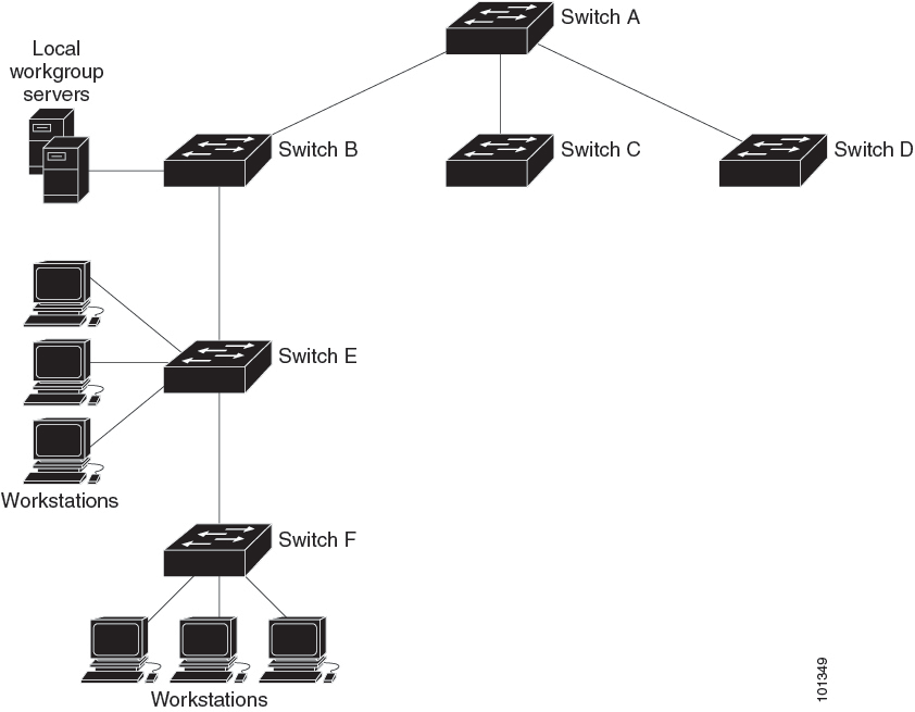
The figure below shows a typical network example using NTP. Device A is the NTP primary (formerly known as NTP primary), with the Device B, C, and D configured in NTP server mode, in server association with Device A. Device E is configured as an NTP peer to the upstream and downstream Device, Device B and Device F, respectively.

Figure 1. Typical NTP Network Configuration


If the network is isolated from the Internet, Cisco’s implementation of NTP allows a device to act as if it is synchronized through NTP, when in fact it has learned the time by using other means. Other devices then synchronize to that device through NTP.

When multiple sources of time are available, NTP is always considered to be more authoritative. NTP time overrides the time set by any other method.

Several manufacturers include NTP software for their host systems, and a publicly available version for systems running UNIX and its various derivatives is also available. This software allows host systems to be time-synchronized as well.

NTP Stratum

NTP uses the concept of a stratum to describe how many NTP hops away a device is from an authoritative time source. A stratum 1 time server has a radio or atomic clock directly attached, a stratum 2 time server receives its time through NTP from a stratum 1 time server, and so on. A device running NTP automatically chooses as its time source the device with the lowest stratum number with which it communicates through NTP. This strategy effectively builds a self-organizing tree of NTP speakers.

NTP avoids synchronizing to a device whose time might not be accurate by never synchronizing to a device that is not synchronized. NTP also compares the time reported by several devices and does not synchronize to a device whose time is significantly different than the others, even if its stratum is lower.

NTP Associations

The communications between devices running NTP (known as associations) are usually statically configured; each device is given the IP address of all devices with which it should form associations. Accurate timekeeping is possible by exchanging NTP messages between each pair of devices with an association. However, in a LAN environment, NTP can be configured to use IP broadcast messages instead. This alternative reduces configuration complexity because each device can simply be configured to send or receive broadcast messages. However, in that case, information flow is one-way only.

NTP Security

The time kept on a device is a critical resource; you should use the security features of NTP to avoid the accidental or malicious setting of an incorrect time. Two mechanisms are available: an access list-based restriction scheme and an encrypted authentication mechanism.

NTP Implementation

Implementation of NTP does not support stratum 1 service; it is not possible to connect to a radio or atomic clock. We recommend that the time service for your network be derived from the public NTP servers available on the IP Internet.

Figure 2. Typical NTP Network Configuration. The following figure shows a typical network example using NTP. Switch A is the NTP primary, with the Switch B, C, and D configured in NTP server mode, in server association with Switch A. Switch E is configured as an NTP peer to the upstream and downstream switches, Switch B and Switch F, respectively.

If the network is isolated from the Internet, NTP allows a device to act as if it is synchronized through NTP, when in fact it has learned the time by using other means. Other devices then synchronize to that device through NTP.

When multiple sources of time are available, NTP is always considered to be more authoritative. NTP time overrides the time set by any other method.

Several manufacturers include NTP software for their host systems, and a publicly available version for systems running UNIX and its various derivatives is also available. This software allows host systems to be time-synchronized as well.

NTP Version 4

NTP version 4 is implemented on the device. NTPv4 is an extension of NTP version 3. NTPv4 supports both IPv4 and IPv6 and is backward-compatible with NTPv3.

NTPv4 provides these capabilities:

  • Support for IPv6.

  • Improved security compared to NTPv3. The NTPv4 protocol provides a security framework based on public key cryptography and standard X509 certificates.

  • Automatic calculation of the time-distribution hierarchy for a network. Using specific multicast groups, NTPv4 automatically configures the hierarchy of the servers to achieve the best time accuracy for the lowest bandwidth cost. This feature leverages site-local IPv6 multicast addresses.

For details about configuring NTPv4, see the Implementing NTPv4 in IPv6 chapter of the Cisco IOS IPv6 Configuration Guide, Release 12.4T.

System Name and Prompt

You configure the system name on the Device to identify it. By default, the system name and prompt are Switch.

If you have not configured a system prompt, the first 20 characters of the system name are used as the system prompt. A greater-than symbol [>] is appended. The prompt is updated whenever the system name changes.

For complete syntax and usage information for the commands used in this section, see the Cisco IOS Configuration Fundamentals Command Reference, Release 12.4 and the Cisco IOS IP Command Reference, Volume 2 of 3: Routing Protocols, Release 12.4.

Stack System Name and Prompt

If you are accessing a stack member through the active stack, you must use the session stack-member-number privileged EXEC command. The stack member number range is from 1 through 8. When you use this command, the stack member number is appended to the system prompt. For example, Switch-2# is the prompt in privileged EXEC mode for stack member 2, and the system prompt for the switch stack is Switch.

Default System Name and Prompt Configuration

The default switch system name and prompt is Switch.

DNS

The DNS protocol controls the Domain Name System (DNS), a distributed database with which you can map hostnames to IP addresses. When you configure DNS on your device, you can substitute the hostname for the IP address with all IP commands, such as ping , telnet , connect , and related Telnet support operations.

IP defines a hierarchical naming scheme that allows a device to be identified by its location or domain. Domain names are pieced together with periods (.) as the delimiting characters. For example, Cisco Systems is a commercial organization that IP identifies by a com domain name, so its domain name is cisco.com. A specific device in this domain, for example, the File Transfer Protocol (FTP) system is identified as ftp.cisco.com.

To keep track of domain names, IP has defined the concept of a domain name server, which holds a cache (or database) of names mapped to IP addresses. To map domain names to IP addresses, you must first identify the hostnames, specify the name server that is present on your network, and enable the DNS.

Default DNS Settings

Table 1. Default DNS Settings

Feature

Default Setting

DNS enable state

Enabled.

DNS default domain name

None configured.

DNS servers

No name server addresses are configured.

Login Banners

You can configure a message-of-the-day (MOTD) and a login banner. The MOTD banner is displayed on all connected terminals at login and is useful for sending messages that affect all network users (such as impending system shutdowns).

The login banner is also displayed on all connected terminals. It appears after the MOTD banner and before the login prompts.


Note


For complete syntax and usage information for the commands used in this section, see the Cisco IOS Configuration Fundamentals Command Reference, Release 12.4.


Default Banner Configuration

The MOTD and login banners are not configured.

MAC Address Table

The MAC address table contains address information that the device uses to forward traffic between ports. All MAC addresses in the address table are associated with one or more ports. The address table includes these types of addresses:

  • Dynamic address—A source MAC address that the device learns and then ages when it is not in use.

  • Static address—A manually entered unicast address that does not age and that is not lost when the device resets.

The address table lists the destination MAC address, the associated VLAN ID, and port number associated with the address and the type (static or dynamic).


Note


For complete syntax and usage information for the commands used in this section, see the command reference for this release.


MAC Address Table Creation

With multiple MAC addresses supported on all ports, you can connect any port on the device to other network devices. The device provides dynamic addressing by learning the source address of packets it receives on each port and adding the address and its associated port number to the address table. As devices are added or removed from the network, the device updates the address table, adding new dynamic addresses and aging out those that are not in use.

The aging interval is globally configured. However, the device maintains an address table for each VLAN, and STP can accelerate the aging interval on a per-VLAN basis.

The device sends packets between any combination of ports, based on the destination address of the received packet. Using the MAC address table, the device forwards the packet only to the port associated with the destination address. If the destination address is on the port that sent the packet, the packet is filtered and not forwarded. The device always uses the store-and-forward method: complete packets are stored and checked for errors before transmission.

MAC Addresses and VLANs

All addresses are associated with a VLAN. An address can exist in more than one VLAN and have different destinations in each. Unicast addresses, for example, could be forwarded to port 1 in VLAN 1 and ports 9, 10, and 1 in VLAN 5.

Each VLAN maintains its own logical address table. A known address in one VLAN is unknown in another until it is learned or statically associated with a port in the other VLAN.

Default MAC Address Table Settings

The following table shows the default settings for the MAC address table.

Table 2. Default Settings for the MAC Address

Feature

Default Setting

Aging time

300 seconds

Dynamic addresses

Automatically learned

Static addresses

None configured

ARP Table Management

To communicate with a device (over Ethernet, for example), the software first must learn the 48-bit MAC address or the local data link address of that device. The process of learning the local data link address from an IP address is called address resolution .

The Address Resolution Protocol (ARP) associates a host IP address with the corresponding media or MAC addresses and the VLAN ID. Using an IP address, ARP finds the associated MAC address. When a MAC address is found, the IP-MAC address association is stored in an ARP cache for rapid retrieval. Then the IP datagram is encapsulated in a link-layer frame and sent over the network. Encapsulation of IP datagrams and ARP requests and replies on IEEE 802 networks other than Ethernet is specified by the Subnetwork Access Protocol (SNAP). By default, standard Ethernet-style ARP encapsulation (represented by the arpa keyword) is enabled on the IP interface.

ARP entries added manually to the table do not age and must be manually removed.

For CLI procedures, see the Cisco IOS Release 12.4 documentation on Cisco.com.

How to Administer the Device

Configuring the Time and Date Manually

System time remains accurate through restarts and reboot, however, you can manually configure the time and date after the system is restarted.

We recommend that you use manual configuration only when necessary. If you have an outside source to which the device can synchronize, you do not need to manually set the system clock.

Setting the System Clock

If you have an outside source on the network that provides time services, such as an NTP server, you do not need to manually set the system clock.

Follow these steps to set the system clock:

Procedure
  Command or Action Purpose

Step 1

enable

Example:

Device> enable

Enables privileged EXEC mode.

  • Enter your password if prompted.

Step 2

Use one of the following:

  • clock set hh:mm:ss day month year
  • clock set hh:mm:ss month day year
Example:

Device# clock set 13:32:00 23 March 2013

Manually set the system clock using one of these formats:

  • hh:mm:ss— Specifies the time in hours (24-hour format), minutes, and seconds. The time specified is relative to the configured time zone.

  • day— Specifies the day by date in the month.

  • month— Specifies the month by name.

  • year— Specifies the year (no abbreviation).

Configuring the Time Zone

Follow these steps to manually configure the time zone:
Procedure
  Command or Action Purpose

Step 1

enable

Example:

Device> enable

Enables privileged EXEC mode.

  • Enter your password if prompted.

Step 2

configure terminal

Example:

Device# configure terminal

Enters global configuration mode.

Step 3

clock timezone zone hours-offset [minutes-offset]

Example:

Device(config)# clock timezone AST -3 30

Sets the time zone.

Internal time is kept in Coordinated Universal Time (UTC), so this command is used only for display purposes and when the time is manually set.

  • zone— Enters the name of the time zone to be displayed when standard time is in effect. The default is UTC.

  • hours-offset— Enters the hours offset from UTC.

  • (Optional) minutes-offset— Enters the minutes offset from UTC. This available where the local time zone is a percentage of an hour different from UTC.

Step 4

end

Example:

Device(config)# end

Returns to privileged EXEC mode.

Step 5

show running-config

Example:

Device# show running-config 

Verifies your entries.

Step 6

copy running-config startup-config

Example:

Device# copy running-config startup-config 

(Optional) Saves your entries in the configuration file.

Configuring Summer Time (Daylight Saving Time)

To configure summer time (daylight saving time) in areas where it starts and ends on a particular day of the week each year, perform this task:

Procedure
  Command or Action Purpose

Step 1

enable

Example:

Device> enable

Enables privileged EXEC mode.

  • Enter your password if prompted.

Step 2

configure terminal

Example:

Device# configure terminal

Enters global configuration mode.

Step 3

clock summer-time zone date date month year hh:mm date month year hh:mm [offset]]

Example:

Device(config)# clock summer-time PDT date 
10 March 2013 2:00 3 November 2013 2:00

Configures summer time to start and end on specified days every year.

Step 4

clock summer-time zone recurring [week day month hh:mm week day month hh:mm [offset]]

Example:

Device(config)# clock summer-time 
PDT recurring 10 March 2013 2:00 3 November 2013 2:00

Configures summer time to start and end on the specified days every year. All times are relative to the local time zone. The start time is relative to standard time.

The end time is relative to summer time. Summer time is disabled by default. If you specify clock summer-time zone recurring without parameters, the summer time rules default to the United States rules.

If the starting month is after the ending month, the system assumes that you are in the southern hemisphere.

  • zone— Specifies the name of the time zone (for example, PDT) to be displayed when summer time is in effect.

  • (Optional) week— Specifies the week of the month (1 to 4, first , or last ).

  • (Optional) day— Specifies the day of the week (Sunday, Monday...).

  • (Optional) month— Specifies the month (January, February...).

  • (Optional) hh:mm— Specifies the time (24-hour format) in hours and minutes.

  • (Optional) offset— Specifies the number of minutes to add during summer time. The default is 60.

Step 5

end

Example:

Device(config)# end

Returns to privileged EXEC mode.

Step 6

show running-config

Example:

Device# show running-config 

Verifies your entries.

Step 7

copy running-config startup-config

Example:

Device# copy running-config startup-config 

(Optional) Saves your entries in the configuration file.

Follow these steps if summer time in your area does not follow a recurring pattern (configure the exact date and time of the next summer time events):

Procedure
  Command or Action Purpose

Step 1

enable

Example:

Device> enable

Enables privileged EXEC mode.

  • Enter your password if prompted.

Step 2

configure terminal

Example:

Device# configure terminal

Enters global configuration mode.

Step 3

clock summer-time zone date[ month date year hh:mm month date year hh:mm [offset]] orclock summer-time zone date [date month year hh:mm date month year hh:mm [offset]]

Configures summer time to start on the first date and end on the second date.

Summer time is disabled by default.
  • For zone , specify the name of the time zone (for example, PDT) to be displayed when summer time is in effect.

  • (Optional) For week , specify the week of the month (1 to 5 or last).

  • (Optional) For day , specify the day of the week (Sunday, Monday...).

  • (Optional) For month , specify the month (January, February...).

  • (Optional) For hh:mm , specify the time (24-hour format) in hours and minutes.

  • (Optional) For offset , specify the number of minutes to add during summer time. The default is 60.

Step 4

end

Example:

Device(config)# end

Returns to privileged EXEC mode.

Step 5

show running-config

Example:

Device# show running-config 

Verifies your entries.

Step 6

copy running-config startup-config

Example:

Device# copy running-config startup-config 

(Optional) Saves your entries in the configuration file.

Configuring a System Name

Follow these steps to manually configure a system name:

Procedure

  Command or Action Purpose

Step 1

enable

Example:


Device> enable

Enables privileged EXEC mode.

  • Enter your password if prompted.

Step 2

configure terminal

Example:


Device# configure terminal

Enters global configuration mode.

Step 3

hostname name

Example:


Device(config)# hostname 
remote-users

Configures a system name. When you set the system name, it is also used as the system prompt.

The default setting is Switch.

The name must follow the rules for ARPANET hostnames. They must start with a letter, end with a letter or digit, and have as interior characters only letters, digits, and hyphens. Names can be up to 63 characters.

Step 4

end

Example:

remote-users(config)#end
remote-users#

Returns to priviliged EXEC mode.

Step 5

show running-config

Example:


Device# show running-config 

Verifies your entries.

Step 6

copy running-config startup-config

Example:


Device# copy running-config startup-config 

(Optional) Saves your entries in the configuration file.

Setting Up DNS

If you use the device IP address as its hostname, the IP address is used and no DNS query occurs. If you configure a hostname that contains no periods (.), a period followed by the default domain name is appended to the hostname before the DNS query is made to map the name to an IP address. The default domain name is the value set by the ip domain-name global configuration command. If there is a period (.) in the hostname, the Cisco IOS software looks up the IP address without appending any default domain name to the hostname.

Follow these steps to set up your switch to use the DNS:

Procedure

  Command or Action Purpose

Step 1

enable

Example:


Device> enable

Enables privileged EXEC mode.

  • Enter your password if prompted.

Step 2

configure terminal

Example:


Device# configure terminal

Enters global configuration mode.

Step 3

ip domain-name name

Example:


Device(config)# ip domain-name Cisco.com

Defines a default domain name that the software uses to complete unqualified hostnames (names without a dotted-decimal domain name).

Do not include the initial period that separates an unqualified name from the domain name.

At boot time, no domain name is configured; however, if the device configuration comes from a BOOTP or Dynamic Host Configuration Protocol (DHCP) server, then the default domain name might be set by the BOOTP or DHCP server (if the servers were configured with this information).

Step 4

ip name-server server-address1 [server-address2 ... server-address6]

Example:


Device(config)# ip 
name-server 192.168.1.100 
192.168.1.200 192.168.1.300

Specifies the address of one or more name servers to use for name and address resolution.

You can specify up to six name servers. Separate each server address with a space. The first server specified is the primary server. The device sends DNS queries to the primary server first. If that query fails, the backup servers are queried.

Step 5

ip domain-lookup [nsap | source-interface interface]

Example:


Device(config)# ip domain-lookup

(Optional) Enables DNS-based hostname-to-address translation on your device. This feature is enabled by default.

If your network devices require connectivity with devices in networks for which you do not control name assignment, you can dynamically assign device names that uniquely identify your devices by using the global Internet naming scheme (DNS).

Step 6

end

Example:


Device(config)# end

Returns to privileged EXEC mode.

Step 7

show running-config

Example:


Device# show running-config 

Verifies your entries.

Step 8

copy running-config startup-config

Example:


Device# copy running-config startup-config 

(Optional) Saves your entries in the configuration file.

Configuring a Message-of-the-Day Login Banner

You can create a single or multiline message banner that appears on the screen when someone logs in to the device

Follow these steps to configure a MOTD login banner:

Procedure

  Command or Action Purpose

Step 1

enable

Example:


Device> enable

Enables privileged EXEC mode.

  • Enter your password if prompted.

Step 2

configure terminal

Example:


Device# configure terminal

Enters global configuration mode.

Step 3

banner motd c message c

Example:


Device(config)# banner motd # 
This is a secure site. Only 
authorized users are allowed.
For access, contact technical 
support.
#

Specifies the message of the day.

c— Enters the delimiting character of your choice, for example, a pound sign (#), and press the Return key. The delimiting character signifies the beginning and end of the banner text. Characters after the ending delimiter are discarded.

message— Enters a banner message up to 255 characters. You cannot use the delimiting character in the message.

Step 4

end

Example:


Device(config)# end

Returns to privileged EXEC mode.

Step 5

show running-config

Example:


Device# show running-config 

Verifies your entries.

Step 6

copy running-config startup-config

Example:


Device# copy running-config startup-config 

(Optional) Saves your entries in the configuration file.

Configuring a Login Banner

You can configure a login banner to be displayed on all connected terminals. This banner appears after the MOTD banner and before the login prompt.

Follow these steps to configure a login banner:

Procedure

  Command or Action Purpose

Step 1

enable

Example:


Device> enable

Enables privileged EXEC mode.

  • Enter your password if prompted.

Step 2

configure terminal

Example:


Device# configure terminal

Enters global configuration mode.

Step 3

banner login c message c

Example:


Device(config)# banner login $
Access for authorized users only. 
Please enter your username and 
password.
$

Specifies the login message.

c— Enters the delimiting character of your choice, for example, a pound sign (#), and press the Return key. The delimiting character signifies the beginning and end of the banner text. Characters after the ending delimiter are discarded.

message— Enters a login message up to 255 characters. You cannot use the delimiting character in the message.

Step 4

end

Example:


Device(config)# end

Returns to privileged EXEC mode.

Step 5

show running-config

Example:


Device# show running-config 

Verifies your entries.

Step 6

copy running-config startup-config

Example:


Device# copy running-config startup-config 

(Optional) Saves your entries in the configuration file.

Managing the MAC Address Table

Changing the Address Aging Time

Follow these steps to configure the dynamic address table aging time:

Procedure
  Command or Action Purpose

Step 1

enable

Example:

Device> enable

Enables privileged EXEC mode.

  • Enter your password if prompted.

Step 2

configure terminal

Example:

Device# configure terminal

Enters global configuration mode.

Step 3

mac address-table aging-time [0 | 10-1000000] [routed-mac | vlan vlan-id]

Example:

Device(config)# mac address-table 
aging-time 500 vlan 2

Sets the length of time that a dynamic entry remains in the MAC address table after the entry is used or updated.

The range is 10 to 1000000 seconds. The default is 300. You can also enter 0, which disables aging. Static address entries are never aged or removed from the table.

vlan-id— Valid IDs are 1 to 4094.

Step 4

end

Example:

Device(config)# end

Returns to privileged EXEC mode.

Step 5

show running-config

Example:

Device# show running-config 

Verifies your entries.

Step 6

copy running-config startup-config

Example:

Device# copy running-config startup-config 

(Optional) Saves your entries in the configuration file.

Configuring MAC Address Change Notification Traps

Follow these steps to configure the switch to send MAC address change notification traps to an NMS host:

Procedure
  Command or Action Purpose

Step 1

enable

Example:

Device> enable

Enables privileged EXEC mode.

  • Enter your password if prompted.

Step 2

configure terminal

Example:

Device# configure terminal

Enters global configuration mode.

Step 3

snmp-server host host-addr community-string notification-type { informs | traps } {version {1 | 2c | 3}} {vrf vrf instance name}

Example:

Device(config)# snmp-server host 
172.20.10.10 traps private mac-notification

Specifies the recipient of the trap message.

  • host-addr— Specifies the name or address of the NMS.

  • traps (the default) Sends SNMP traps to the host.

  • informs Sends SNMP informs to the host.

  • version Specifies the SNMP version to support. Version 1, the default, is not available with informs.

  • community-string— Specifies the string to send with the notification operation. Though you can set this string by using the snmp-server host command, we recommend that you define this string by using the snmp-server community command before using the snmp-server host command.

  • notification-type— Uses the mac-notification keyword.

  • vrf vrf instance name Specifies the VPN routing/forwarding instance for this host.

Step 4

snmp-server enable traps mac-notification change

Example:

Device(config)# snmp-server enable traps 
mac-notification change

Enables the device to send MAC address change notification traps to the NMS.

Step 5

mac address-table notification change

Example:

Device(config)# mac address-table 
notification change

Enables the MAC address change notification feature.

Step 6

mac address-table notification change [interval value] [history-size value]

Example:

Device(config)# mac address-table 
notification change interval 123
Device(config)#mac address-table 
notification change history-size 100

Enters the trap interval time and the history table size.

  • (Optional) interval value— Specifies the notification trap interval in seconds between each set of traps that are generated to the NMS. The range is 0 to 2147483647 seconds; the default is 1 second.

  • (Optional) history-size value— Specifies the maximum number of entries in the MAC notification history table. The range is 0 to 500; the default is 1.

Step 7

interface interface-id

Example:

Device(config)# interface 
gigabitethernet 1/0/2

Enters interface configuration mode, and specifies the Layer 2 interface on which to enable the SNMP MAC address notification trap.

Step 8

snmp trap mac-notification change {added | removed}

Example:

Device(config-if)# snmp trap 
mac-notification change added

Enables the MAC address change notification trap on the interface.

  • Enables the trap when a MAC address is added on this interface.

  • Enables the trap when a MAC address is removed from this interface.

Step 9

end

Example:

Device(config)# end

Returns to privileged EXEC mode.

Step 10

show running-config

Example:

Device# show running-config 

Verifies your entries.

Step 11

copy running-config startup-config

Example:

Device# copy running-config startup-config 

(Optional) Saves your entries in the configuration file.

Configuring MAC Address Move Notification Traps

When you configure MAC-move notification, an SNMP notification is generated and sent to the network management system whenever a MAC address moves from one port to another within the same VLAN.

Follow these steps to configure the device to send MAC address-move notification traps to an NMS host:

Procedure
  Command or Action Purpose

Step 1

enable

Example:

Device> enable

Enables privileged EXEC mode.

  • Enter your password if prompted.

Step 2

configure terminal

Example:

Device# configure terminal

Enters global configuration mode.

Step 3

snmp-server host host-addr {traps | informs} {version {1 | 2c | 3}} community-string notification-type

Example:

Device(config)# snmp-server host 
172.20.10.10 traps private mac-notification

Specifies the recipient of the trap message.

  • host-addr— Specifies the name or address of the NMS.

  • traps (the default) Sends SNMP traps to the host.

  • informs Sends SNMP informs to the host.

  • version Specifies the SNMP version to support. Version 1, the default, is not available with informs.

  • community-string— Specifies the string to send with the notification operation. Though you can set this string by using the snmp-server host command, we recommend that you define this string by using the snmp-server community command before using the snmp-server host command.

  • notification-type— Uses the mac-notification keyword.

Step 4

snmp-server enable traps mac-notification move

Example:

Device(config)# snmp-server enable traps 
mac-notification move

Enables the device to send MAC address move notification traps to the NMS.

Step 5

mac address-table notification mac-move

Example:

Device(config)# mac address-table 
notification mac-move

Enables the MAC address move notification feature.

Step 6

end

Example:

Device(config)# end

Returns to privileged EXEC mode.

Step 7

show running-config

Example:

Device# show running-config 

Verifies your entries.

Step 8

copy running-config startup-config

Example:

Device# copy running-config startup-config 

(Optional) Saves your entries in the configuration file.

What to do next

To disable MAC address-move notification traps, use the no snmp-server enable traps mac-notification move global configuration command. To disable the MAC address-move notification feature, use the no mac address-table notification mac-move global configuration command.

You can verify your settings by entering the show mac address-table notification mac-move privileged EXEC commands.

Configuring MAC Threshold Notification Traps

When you configure MAC threshold notification, an SNMP notification is generated and sent to the network management system when a MAC address table threshold limit is reached or exceeded.

Procedure
  Command or Action Purpose

Step 1

configure terminal

Example:

Device# configure terminal

Enters global configuration mode.

Step 2

snmp-server host host-addr {traps | informs} {version {1 | 2c | 3}} community-string notification-type

Example:

Device(config)# snmp-server host 
172.20.10.10 traps private 
mac-notification

Specifies the recipient of the trap message.

  • host-addr— Specifies the name or address of the NMS.

  • traps (the default) Sends SNMP traps to the host.

  • informs Sends SNMP informs to the host.

  • version Specifies the SNMP version to support. Version 1, the default, is not available with informs.

  • community-string— Specifies the string to send with the notification operation. You can set this string by using the snmp-server host command, but we recommend that you define this string by using the snmp-server community command before using the snmp-server host command.

  • notification-type— Uses the mac-notification keyword.

Step 3

snmp-server enable traps mac-notification threshold

Example:

Device(config)# snmp-server enable traps 
mac-notification threshold

Enables MAC threshold notification traps to the NMS.

Step 4

mac address-table notification threshold

Example:

Device(config)# mac address-table 
notification threshold

Enables the MAC address threshold notification feature.

Step 5

mac address-table notification threshold [limit percentage] | [interval time]

Example:

Device(config)# mac address-table 
notification threshold interval 123
Device(config)# mac address-table 
notification threshold limit 78

Enters the threshold value for the MAC address threshold usage monitoring.

  • (Optional) limit percentage— Specifies the percentage of the MAC address table use; valid values are from 1 to 100 percent. The default is 50 percent.

  • (Optional) interval time— Specifies the time between notifications; valid values are greater than or equal to 120 seconds. The default is 120 seconds.

Step 6

end

Example:

Device(config)# end

Returns to privileged EXEC mode.

Adding and Removing Static Address Entries

Follow these steps to add a static address:

Procedure
  Command or Action Purpose

Step 1

enable

Example:

Device> enable

Enables privileged EXEC mode.

  • Enter your password if prompted.

Step 2

configure terminal

Example:

Device# configure terminal

Enters global configuration mode.

Step 3

mac address-table static mac-addr vlan vlan-id interface interface-id

Example:

Device(config)# mac address-table 
static c2f3.220a.12f4 vlan 4 interface gigabitethernet 1/0/1

Adds a static address to the MAC address table.

  • mac-addr— Specifies the destination MAC unicast address to add to the address table. Packets with this destination address received in the specified VLAN are forwarded to the specified interface.

  • vlan-id— Specifies the VLAN for which the packet with the specified MAC address is received. Valid VLAN IDs are 1 to 4094.

  • interface-id— Specifies the interface to which the received packet is forwarded. Valid interfaces include physical ports or port channels. For static multicast addresses, you can enter multiple interface IDs. For static unicast addresses, you can enter only one interface at a time, but you can enter the command multiple times with the same MAC address and VLAN ID.

Step 4

end

Example:
Device(config)# end

Returns to privileged EXEC mode. Alternatively, you can also press Ctrl-Z to exit global configuration mode.

Step 5

show running-config

Example:

Device# show running-config 

Verifies your entries.

Step 6

copy running-config startup-config

Example:

Device# copy running-config startup-config 

(Optional) Saves your entries in the configuration file.

Configuring Unicast MAC Address Filtering

Follow these steps to configure the Device to drop a source or destination unicast static address:

Procedure
  Command or Action Purpose

Step 1

enable

Example:

Device> enable

Enables privileged EXEC mode.

  • Enter your password if prompted.

Step 2

configure terminal

Example:

Device# configure terminal

Enters global configuration mode.

Step 3

mac address-table static mac-addr vlan vlan-id drop

Example:

Device(config)# mac address-table 
static c2f3.220a.12f4 vlan 4 drop

Enables unicast MAC address filtering and configure the device to drop a packet with the specified source or destination unicast static address.

  • mac-addr— Specifies a source or destination unicast MAC address (48-bit). Packets with this MAC address are dropped.

  • vlan-id— Specifies the VLAN for which the packet with the specified MAC address is received. Valid VLAN IDs are 1 to 4094.

Step 4

end

Example:

Device(config)# end

Returns to privileged EXEC mode.

Step 5

show running-config

Example:

Device# show running-config 

Verifies your entries.

Step 6

copy running-config startup-config

Example:

Device# copy running-config startup-config 

(Optional) Saves your entries in the configuration file.

Monitoring and Maintaining Administration of the Device

Command Purpose

clear mac address-table dynamic

Removes all dynamic entries.

clear mac address-table dynamic address mac-address

Removes a specific MAC address.

clear mac address-table dynamic interface interface-id

Removes all addresses on the specified physical port or port channel.

clear mac address-table dynamic vlan vlan-id

Removes all addresses on a specified VLAN.

show clock [detail]

Displays the time and date configuration.

show ip igmp snooping groups

Displays the Layer 2 multicast entries for all VLANs or the specified VLAN.

show mac address-table address mac-address

Displays MAC address table information for the specified MAC address.

show mac address-table aging-time

Displays the aging time in all VLANs or the specified VLAN.

show mac address-table count

Displays the number of addresses present in all VLANs or the specified VLAN.

show mac address-table dynamic

Displays only dynamic MAC address table entries.

show mac address-table interface interface-name

Displays the MAC address table information for the specified interface.

show mac address-table move update

Displays the MAC address table move update information.

show mac address-table multicast

Displays a list of multicast MAC addresses.

show mac address-table notification {change | mac-move | threshold}

Displays the MAC notification parameters and history table.

show mac address-table secure

Displays the secure MAC addresses.

show mac address-table static

Displays only static MAC address table entries.

show mac address-table vlan vlan-id

Displays the MAC address table information for the specified VLAN.

Configuration Examples for Device Administration

Example: Setting the System Clock

This example shows how to manually set the system clock:


Device# clock set 13:32:00 23 July 2013

Examples: Configuring Summer Time

This example (for daylight savings time) shows how to specify that summer time starts on March 10 at 02:00 and ends on November 3 at 02:00:


Device(config)# clock summer-time PDT recurring PST date 
10 March 2013 2:00 3 November 2013 2:00

This example shows how to set summer time start and end dates:


Device(config)#clock summer-time PST date 
20 March 2013 2:00 20 November 2013 2:00

Example: Configuring a MOTD Banner

This example shows how to configure a MOTD banner by using the pound sign (#) symbol as the beginning and ending delimiter:

 
Device(config)# banner motd #

This is a secure site. Only authorized users are allowed.
For access, contact technical support.

#

Device(config)#

This example shows the banner that appears from the previous configuration:


Unix> telnet 192.0.2.15

Trying 192.0.2.15...

Connected to 192.0.2.15.

Escape character is '^]'.

This is a secure site. Only authorized users are allowed.

For access, contact technical support.

User Access Verification

Password:

Example: Configuring a Login Banner

This example shows how to configure a login banner by using the dollar sign ($) symbol as the beginning and ending delimiter:


Device(config)# banner login $

Access for authorized users only. Please enter your username and password.

$

Device(config)#

Example: Configuring MAC Address Change Notification Traps

This example shows how to specify 172.20.10.10 as the NMS, enable MAC address notification traps to the NMS, enable the MAC address-change notification feature, set the interval time to 123 seconds, set the history-size to 100 entries, and enable traps whenever a MAC address is added on the specified port:


Device(config)# snmp-server host 172.20.10.10 traps private mac-notification
Device(config)# snmp-server enable traps mac-notification change
Device(config)# mac address-table notification change 
Device(config)# mac address-table notification change interval 123
Device(config)# mac address-table notification change history-size 100
Device(config)# interface gigabitethernet 1/2/1
Device(config-if)# snmp trap mac-notification change added

Example: Configuring MAC Threshold Notification Traps

This example shows how to specify 172.20.10.10 as the NMS, enable the MAC address threshold notification feature, set the interval time to 123 seconds, and set the limit to 78 per cent:


Device(config)# snmp-server host 172.20.10.10 traps private mac-notification
Device(config)# snmp-server enable traps mac-notification threshold
Device(config)# mac address-table notification threshold
Device(config)# mac address-table notification threshold interval 123
Device(config)# mac address-table notification threshold limit 78

Example: Adding the Static Address to the MAC Address Table

This example shows how to add the static address c2f3.220a.12f4 to the MAC address table. When a packet is received in VLAN 4 with this MAC address as its destination address, the packet is forwarded to the specified port:


Note


You cannot associate the same static MAC address to multiple interfaces. If the command is executed again with a different interface, the static MAC address is overwritten on the new interface.


Device(config)# mac address-table static c2f3.220a.12f4 vlan 4 interface gigabitethernet 1/1/1

Example: Configuring Unicast MAC Address Filtering

This example shows how to enable unicast MAC address filtering and how to configure drop packets that have a source or destination address of c2f3.220a.12f4. When a packet is received in VLAN 4 with this MAC address as its source or destination, the packet is dropped:


Device(config)# mac address-table static c2f3.220a.12f4 vlan 4 drop

Additional References for Switch Administration

Related Documents

Related Topic Document Title

Switch administration commands

Catalyst 2960-X Switch System Management Command Reference

Network management configuration

Catalyst 2960-X Switch Network Management Configuration Guide

Layer 2 configuration

Catalyst 2960-X Switch Layer 2 Configuration Guide

VLAN configuration

Catalyst 2960-X Switch VLAN Management Configuration Guide

Platform-independent command references

Cisco IOS 15.3M&T Command References

Platform-independent configuration information

Cisco IOS 15.3M&T Configuration Guides

Standards and RFCs

Standard/RFC Title
None

MIBs

MIB MIBs Link

All supported MIBs for this release.

To locate and download MIBs for selected platforms, Cisco IOS releases, and feature sets, use Cisco MIB Locator found at the following URL:

http://www.cisco.com/go/mibs

Technical Assistance

Description Link

The Cisco Support website provides extensive online resources, including documentation and tools for troubleshooting and resolving technical issues with Cisco products and technologies.

To receive security and technical information about your products, you can subscribe to various services, such as the Product Alert Tool (accessed from Field Notices), the Cisco Technical Services Newsletter, and Really Simple Syndication (RSS) Feeds.

Access to most tools on the Cisco Support website requires a Cisco.com user ID and password.

http://www.cisco.com/support

Feature History and Information for Device Administration

Release

Modification

Cisco IOS Release 15.0(2)EX

This feature was introduced.