Prerequisites for Configuring Tunneling
The following sections list prerequisites and considerations for configuring IEEE 802.1Q and Layer 2 protocol tunneling.
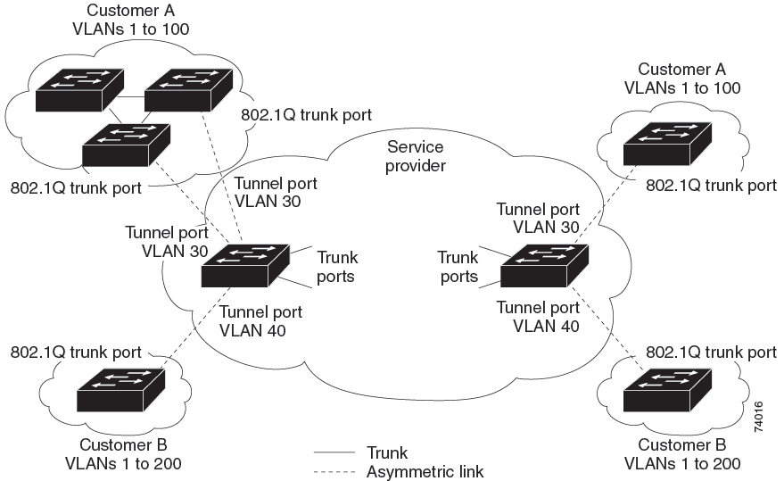
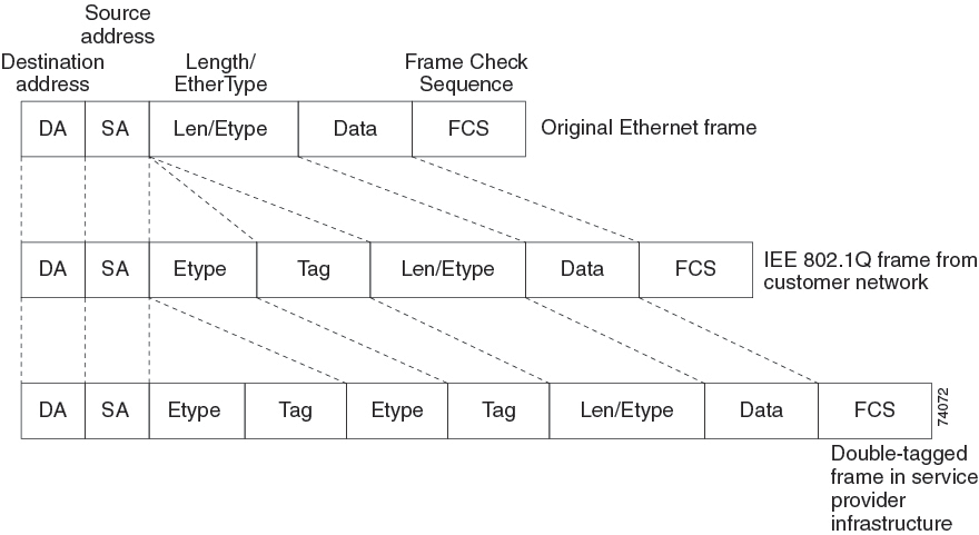
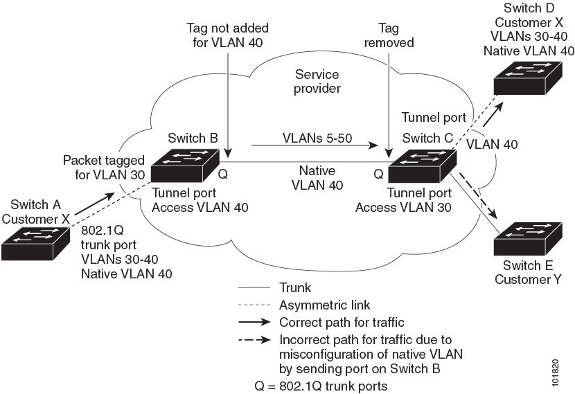
IEEE 802.1Q Tunneling
Although IEEE 802.1Q tunneling works well for Layer 2 packet switching, there are incompatibilities between some Layer 2 features and Layer 3 switching.
-
A tunnel port cannot be a routed port.
-
IP routing is not supported on a VLAN that includes IEEE 802.1Q tunnel ports. Packets received from a tunnel port are forwarded based only on Layer 2 information. If routing is enabled on a device virtual interface (SVI) that includes tunnel ports, untagged IP packets received from the tunnel port are recognized and routed by the device. Customers can access the Internet through its native VLAN. If this access is not needed, you should not configure SVIs on VLANs that include tunnel ports.
-
Fallback bridging is not supported on tunnel ports. Because all IEEE 802.1Q-tagged packets received from a tunnel port are treated as non-IP packets, if fallback bridging is enabled on VLANs that have tunnel ports configured, IP packets would be improperly bridged across VLANs. Therefore, you must not enable fallback bridging on VLANs with tunnel ports.
-
Tunnel ports do not support IP access control lists (ACLs).
-
Layer 3 quality of service (QoS) ACLs and other QoS features related to Layer 3 information are not supported on tunnel ports. MAC-based QoS is supported on tunnel ports.
-
EtherChannel port groups are compatible with tunnel ports as long as the IEEE 802.1Q configuration is consistent within an EtherChannel port group.
-
Port Aggregation Protocol (PAgP), Link Aggregation Control Protocol (LACP), and UniDirectional Link Detection (UDLD) are supported on IEEE 802.1Q tunnel ports.
-
Dynamic Trunking Protocol (DTP) is not compatible with IEEE 802.1Q tunneling because you must manually configure asymmetric links with tunnel ports and trunk ports.
-
VLAN Trunking Protocol (VTP) does not work between devices that are connected by an asymmetrical link or devices that communicate through a tunnel.
-
Loopback detection is supported on IEEE 802.1Q tunnel ports.
-
When a port is configured as an IEEE 802.1Q tunnel port, spanning-tree bridge protocol data unit (BPDU) filtering is automatically enabled on the interface. Cisco Discovery Protocol (CDP) and the Layer Link Discovery Protocol (LLDP) are automatically disabled on the interface.
 Feedback