Configuring IPsec

Restrictions for IPsec

General Restrictions for IPsec

  • Crypto maps are not supported.

  • Only tunnel mode is supported.

  • Volume-based rekeying is not supported.

  • IPsec tunnels are not supported on an MPLS cloud.

  • IPsec tunnels are not supported on vrf lite.

  • A maximum of 128 source IPv4 addresses can be used as a tunnel source IP address (loopback address).

  • A maximum of 128 source IPv6 addresses can be used as a tunnel source IP address (loopback address).

  • The maximum number of IPsec IPv4 Static Virtual Tunnel Interfaces (SVTIs) supported is 480. The maximum number of IPsec IPv6 SVTIs supported is 240. This is a unidimensional scale number. If you enable other features which share the same resource, the scale number will be reduced.

  • IPv4 tunnel mode and IPv6-overlay-IPv4 do not allow IPv6 addresses.

  • IPv6 tunnel mode and IPv4-overlay-IPv6 do not allow IPv4 addresses.

  • OSPFv3 authentication is not supported with IPsec.

  • Only Internet Key Exchange Version 2 (IKEv2) is supported in IPsec.

  • IPsec supports only the following transform-sets:

    esp-aes esp-sha-hmac (with throughput up to 15 Gbps)

    esp-gcm, esp-gcm 256 (with throughput up to 100 Gbps)


Note


The PHY layer adds an additional 34-38 bytes to the IPsec overhead of egressing packets. This may cause the egressing packets to exceed the MTU configured on the underlay interface, and they will be dropped. You can resolve this by increasing the MTU value of the underlay interface by 38 bytes.


Restrictions for IPsec Virtual Tunnel Interfaces

  • Fragmentation of encrypted packets and reassembling of encrypted fragments is not supported. SVTI's MTU needs to be set smaller than physical interface. Fragmentation can be done before encryption or after decryption.

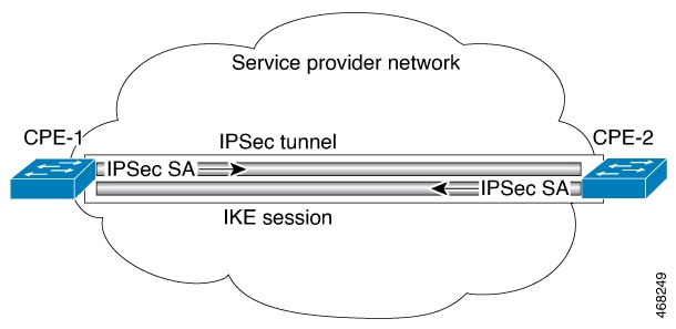
  • The Internet Key Exchange (IKE) security association (SA) is bound to the VTI.

  • By default, Static VTIs (SVTIs) support only a single IPSec SA that is attached to the virtual tunnel interface. The traffic selector for the IPsec SA is always “IP any any” or "IPv6 any any".

  • VTIs do not support traffic selector narrowing down.

  • SVTIs support only the “IP any any” proxy.

  • IPsec stateful failover is not supported with IPSec VTIs.

  • Do not configure the shared keyword when using the tunnel mode ipsec ipv4 command for IPsec IPv4 mode.

  • The traceroute function with crypto offload on VTIs is not supported.

  • Mixed mode is not supported with tunnel mode auto . Mixed mode is not supported with tunnel protection ipsec [shared] .

  • Tunnel source cannot be a subinterface.

Restrictions for IPsec Dead Peer Detection Periodic Message Option

Using periodic Dead Peer Detection (DPD) potentially allows the device to detect an unresponsive IKE peer with faster response time when compared to on-demand DPD. However, use of periodic DPD incurs extra overhead. When communicating to large numbers of IKE peers, with more than 10 crypto sessions, you should consider using on-demand DPD instead.

Information About IPsec

The following topics provide information about IPsec.

IPsec Overview


Note


This feature is supported only on the Cisco Catalyst 9300X Series Switches.


Note


You will need to enable the HSECK9 Key to use this feature. To enable the HSECK9 key refer to theSmart Licensing Using Policy chapter.


A secure network starts with a strong security policy that defines the freedom of access to information and dictates the deployment of security in the network. Cisco Systems offers many technology solutions for building a custom security solution for Internet, extranet, intranet, and remote access networks. These scalable solutions seamlessly interoperate to deploy enterprise-wide network security. Cisco System's IPsec delivers a key technology component for providing a total security solution. Cisco's IPsec offering provides privacy, integrity, and authenticity for transmitting sensitive information over the Internet.

Cisco's end-to-end offering allows customers to implement IPsec transparently into the network infrastructure without affecting individual workstations

IPsec is a framework of open standards for ensuring secure private communications over the Internet. Based on standards developed by the Internet Engineering Task Force (IETF), IPsec ensures confidentiality, integrity, and authenticity of data communications across a public network. IPsec provides a necessary component of a standards-based, flexible solution for deploying a network-wide security policy.

IPsec's method of protecting IP datagrams takes the following forms:

  • Data origin authentication

  • Connectionless data integrity authentication

  • Data content confidentiality

  • Anti-replay protection

  • Limited traffic flow confidentiality

IPsec protects IP datagrams by defining a method of specifying the traffic to protect, how that traffic is to be protected, and to whom the traffic is sent.

By implementing security at the IP level, an organization can ensure secure networking not only for applications that have security mechanisms but also for the many security-ignorant applications. IPsec provides the capability to secure communications across a LAN, across private and public WANs, and across the Internet. Examples of its use include:

  • Secure branch office connectivity over the Internet: A company can build a secure virtual private network over the Internet or over a public WAN. This enables a business to rely heavily on the Internet and reduce its need for private networks, saving costs and network management overhead.

  • Secure remote access over the Internet: An end user whose system is equipped with IP security protocols can make a local call to an Internet Service Provider (ISP) and gain secure access to a company network. This reduces the cost of toll charges for traveling employees and telecommuters.

  • Establishment of extranet and intranet connectivity with partners: IPsec can be used to secure communication with other organizations, ensuring authentication and confidentiality and providing a key exchange mechanism.

  • Enhancement of electronic commerce security: Most efforts to date to secure electronic commerce on the Internet have relied upon securing Web traffic with SSL since that is commonly found in Web browsers and is easy to set up and run. There are new proposals that may utilize IPsec for electronic commerce.

The principal feature of IPsec that enables it to support these varied applications is that it can encrypt or authenticate all traffic at the IP level. Thus, all distributed applications, including remote logon, client/server, e-mail, file transfer, Web access, and so on, can be secured.

Figure 1. IPsec Network

Organizations usually maintain LANs at dispersed locations. In this typical business scenario, traffic on each LAN does not need any special protection, but the devices on the LAN can be protected from the untrusted network with firewalls.

Since we live in a distributed and mobile world, the people who need to access the services on each of the LANs may be at sites across the Internet. This company can use IPsec protocols to protect their access. These protocols can operate in networking devices, such as a router or firewall that connects each LAN to the outside world, or they can operate directly on the workstation or server.

In Fig1, the user workstation connected to one of the CPEs in a customer site can establish an IPsec tunnel with the network devices to protect all the subsequent sessions. After this tunnel is established, the workstation can have many different sessions with the devices behind these IPsec gateways. The packets going across the Internet will be protected by IPsec, but will be delivered onto each LAN as a normal IP packet.

How IPsec Works

IPsec provides secure tunnels between two peers, such as two switches. You define which packets are considered sensitive and should be sent through these secure tunnels. You define the parameters which should be used to protect these sensitive packets, by specifying characteristics of these tunnels. Marked packets are locally redirected to the tunnel interface.

Figure 2. IPsec Tunnel

More accurately, these tunnels are sets of security associations (SAs) that are established between two IPsec peers. The security associations define which protocols and algorithms should be applied to sensitive packets, and also specify the keying material to be used by the two peers. Security associations are unidirectional and are established per security protocol.

If no security association exists that IPsec can use to protect this traffic to the peer, IPsec uses the Internet Key Exchange protocol (IKE) to negotiate with the remote peer to set up the necessary IPsec security associations on behalf of the data flow.

Once established, the set of security associations (outbound, to the peer) is then applied to the triggering packet as well as to subsequent applicable packets as those packets exit the device. Applicable packets are packets that match the same criteria that the original packet matched. For example, all applicable packets could be encrypted before being forwarded to the remote peer. The corresponding inbound security associations are used when processing the incoming traffic from that peer.

If IKE is used to establish the security associations, the security associations will have lifetimes set so that they periodically expire and require renegotiation, thus providing an additional level of security.

Multiple IPsec tunnels can exist between two peers to secure different data streams, with each tunnel using a separate set of security associations. For example, some data streams might be just authenticated while other data streams must both be encrypted and authenticated.

A transform set is an acceptable combination of security protocols, algorithms, and other settings to apply to IPsec protected traffic. During the IPsec security association negotiation, the peers agree to use a particular transform set when protecting a particular data flow.

IPsec implements network layer encryption and authentication, embedding end-to-end security within the network architecture. The advantage to this is that individual applications do not need to be modified to take advantage of strong security. All packets routed through the network are automatically secured.

Information About Internet Key Exchange Version 2

The following sections provide information about Internet Key Exchange Version 2.

IKEv2 Supported Standards

Cisco implements the IP Security (IPsec) Protocol standard for use in Internet Key Exchange Version 2 (IKEv2).


Note


Cisco no longer recommends using DES or MD5 (including HMAC variant); instead, you should use AES and SHA-256. For more information about the latest Cisco cryptographic recommendations, see the Next Generation Encryption (NGE) white paper.

The component technologies implemented in IKEv2 are as follows:

  • AES-CBC—Advanced Encryption Standard-Cipher Block Chaining

  • SHA (HMAC variant)—Secure Hash Algorithm

  • Diffie-Hellman—A public-key cryptography protocol

  • DES—Data Encryption Standard (No longer recommended)

  • MD5 (HMAC [Hash-based Message Authentication Code] variant)—Message digest algorithm 5 (No longer recommended)


Note


Starting from Cisco IOS XE Bengaluru 17.6.x, configuring a weak crypto algorithm generates a warning, but the warning can be safely ignored and does not impact the working of the algorithms. The following example displays a warning message for a weak crypto algorithm:
Device(config-ikev2-proposal)# group 5
%Warning: weaker dh-group is deprecated

The following table lists all the weak algorithms.

IKEv2

DH_GROUP_768_MODP/Group 1

DH_GROUP_1024_MODP/Group 2

DH_GROUP_1536_MODP/Group 5

DES

DES

MD5

Benefits of IKEv2

Dead Peer Detection

Internet Key Exchange Version 2 (IKEv2) provides built-in support for Dead Peer Detection (DPD).

Certificate URLs

Certificates can be referenced through a URL and hash, instead of being sent within IKEv2 packets, to avoid fragmentation.

Denial of Service Attack Resilience

IKEv2 does not process a request until it determines the requester, which addresses to some extent the Denial of Service (DoS) problems in IKEv1, which can be spoofed into performing substantial cryptographic (expensive) processing from false locations.

EAP Support

IKEv2 allows the use of Extensible Authentication Protocol (EAP) for authentication.

Multiple Crypto Engines

If your network has both IPv4 and IPv6 traffic and you have multiple crypto engines, choose one of the following configuration options:

  • One engine handles IPv4 traffic and the other engine handles IPv6 traffic.

  • One engine handles both IPv4 and IPv6 traffic.

Reliability and State Management (Windowing)

IKEv2 uses sequence numbers and acknowledgments to provide reliability, and mandates some error-processing logistics and shared state management.

Internet Key Exchange Version 2 CLI Constructs

IKEv2 Proposal

An Internet Key Exchange Version 2 (IKEv2) proposal is a collection of transforms used in the negotiation of Internet Key Exchange (IKE) security associations (SAs) as part of the IKE_SA_INIT exchange. The transform types used in the negotiation are as follows:

  • Encryption algorithm

  • Integrity algorithm

  • Pseudo-Random Function (PRF) algorithm

  • Diffie-Hellman (DH) group

See the “IKEv2 Smart Defaults” section for information about the default IKEv2 proposal. See the “Configuring Advanced IKEv2 CLI Constructs” section for information about how to override the default IKEv2 proposal and to define new proposals.

IKEv2 Policy

An IKEv2 policy contains proposals that are used to negotiate the encryption, integrity, PRF algorithms, and DH group in the IKE_SA_INIT exchange. It can have match statements, which are used as selection criteria to select a policy during negotiation.

See the “IKEv2 Smart Defaults” section for information about the default IKEv2 policy. See the “Configuring Advanced IKEv2 CLI Constructs” section for information about how to override the default IKEv2 policy and to define new policies.

IKEv2 Profile

An IKEv2 profile is a repository of nonnegotiable parameters of the IKE security association (SA). It includes parameters such as local or remote identities and authentication methods and services. These parameters are available to authenticated peers that match the profile. An IKEv2 profile is attached to either a crypto map or an IPsec profile on the initiator.


Note


Configure the responder-only configuration on the responder device because the IPsec process might fail without this configuration.


IKEv2 Key Ring

An IKEv2 key ring is a repository of symmetric and asymmetric preshared keys and is independent of the IKEv1 key ring. The IKEv2 key ring is associated with an IKEv2 profile and hence supports a set of peers that match the IKEv2 profile. The IKEv2 key ring gets its VPN routing and forwarding (VRF) context from the associated IKEv2 profile.

IKEv2 Smart Defaults

The IKEv2 Smart Defaults feature minimizes configuration steps by covering most of the use cases. IKEv2 smart defaults can be customized for specific use cases, though this is not recommended.

See the “Configuring Advanced IKEv2 CLI Constructs” section for information about how to modify the default IKEv2 constructs.

The following rules apply to the IKEv2 Smart Defaults feature:

  1. A default configuration is displayed in the corresponding show command with default as a keyword and with no argument. For example, the show crypto ikev2 proposal default command displays the default IKEv2 proposal and the show crypto ikev2 proposal command displays the default IKEv2 proposal, along with any user-configured proposals.

  2. A default configuration is displayed in the show running-config all command; it is not displayed in the show running-config command.

  3. You can modify the default configuration, which is displayed in the show running-config all command.

  4. A default configuration can be disabled using the no form of the command; for example, no crypto ikev2 proposal default . A disabled default configuration is not used in negotiation but the configuration is displayed in the show running-config command. A disabled default configuration loses any user modification and restores system-configured values.

  5. A default configuration can be reenabled using the default form of the command, which restores system-configured values; for example, default crypto ikev2 proposal .

  6. The default mode for the default transform set is transport; the default mode for all other transform sets is tunnel.


Note


Cisco no longer recommends using MD5 (including HMAC variant) and Diffie-Hellman (DH) groups 1, 2 and 5; instead, you should use SHA-256 and DH Groups 14 or higher. For more information about the latest Cisco cryptographic recommendations, see the Next Generation Encryption (NGE) white paper.


The following table lists the commands that are enabled with the IKEv2 Smart Defaults feature, along with the default values.

Table 1. IKEv2 Command Defaults

Command Name

Default Values

crypto ikev2 authorization policy


Device# show crypto ikev2 authorization policy default

IKEv2 Authorization policy: default
route set interface
route accept any tag: 1 distance: 2

crypto ikev2 proposal


Device# show crypto ikev2 proposal
 
IKEv2 proposal: default 
Encryption: AES-CBC-256
Integrity: SHA512 SHA384
PRF: SHA512 SHA384
DH Group: DH_GROUP_256_ECP/Group 19 DH_GROUP_2048_MODP/Group 14 DH_GROUP_521_ECP/Group 21 DH_GROUP_1536_MODP/Group 5

crypto ikev2 policy


Device# show crypto ikev2 policy default

IKEv2 policy: default
Match fvrf: any
Match address local: any 
Proposal: default

crypto ipsec profile


Device# show crypto ipsec profile default

IPSEC profile default
Security association lifetime: 4608000 kilobytes/3600 seconds
Responder-Only (Y/N): N
PFS (Y/N): N
Transform sets={
default: { esp-aes esp-sha-hmac },
}

crypto ipsec transform-set


Device# show crypto ipsec transform-set default

Transform set default: { esp-aes esp-sha-hmac }
will negotiate = { Tunnel, },

Note


Before you can use the default IPsec profile, explicitly specify the crypto ipsec profile command on a tunnel interface using the tunnel protection ipsec profile default command.


Note


The 'default' keyword which needs explicit mapping to other CLIs is not supported on a device running on YANG configuration


IKEv2 Suite-B Support

Suite-B is a set of cryptographic algorithms promulgated by the National Security Agency as part of its Cryptographic Modernization Program. Suite-B for Internet Key Exchange (IKE) and IPsec is defined in RFC 4869. The Suite-B components are as follows:

  • Advanced Encryption Standard (AES) 128- and 256-bit keys configured in the IKEv2 proposal. For data traffic, AES should be used in Galois Counter Mode (GCM) that is configured in the IPsec transform set.

  • Elliptic Curve Digital Signature Algorithm (ECDSA) configured in the IKEv2 profile.

  • Secure Hashing Algorithm 2 (SHA-256 and SHA-384) configured in the IKEv2 proposal and IPsec transform set.

Suite-B requirements comprise four user-interface suites of cryptographic algorithms for use with IKE and IPsec. Each suite consists of an encryption algorithm, a digital-signature algorithm, a key-agreement algorithm, and a hash- or message-digest algorithm. See the “Configuring Security for VPNs with IPsec” feature module for detailed information about Cisco Suite-B support.

IPsec Virtual Tunnel Interfaces

The use of IPsec VTIs can simplify the configuration process when you need to provide protection for remote access and it provides an alternative to using generic routing encapsulation (GRE) or Layer 2 Tunneling Protocol (L2TP) tunnels for encapsulation. A benefit of using IPsec VTIs is that the configuration does not require static mapping of IPsec sessions to a physical interface. The IPsec tunnel endpoint is associated with an actual (virtual) interface. Because there is a routable interface at the tunnel endpoint, many common interface capabilities can be applied to the IPsec tunnel.

The IPsec VTI allows for the flexibility of sending and receiving both IP unicast and multicast control packet encrypted traffic on any physical interface, such as in the case of multiple paths. Traffic is encrypted or decrypted when it is forwarded from or to the tunnel interface and is managed by the IP routing table. Using IP routing to forward the traffic to the tunnel interface simplifies the IPsec VPN configuration .

Benefits of Using IPsec Virtual Tunnel Interfaces

IPsec VTIs allow you to configure a virtual interface to which you can apply features. Features for clear-text packets are configured on the VTI. Features for encrypted packets are applied on the physical interface.

There are two types of VTI interfaces: static VTIs (SVTIs) and dynamic VTIs (DVTIs).


Note


Only SVTI is currently supported. DVTI is curretly not supported.


Static Virtual Tunnel Interfaces

SVTI configurations can be used for site-to-site connectivity in which a tunnel provides always-on access between two sites.

The advantage of using SVTIs is that users can enable dynamic routing protocols on the tunnel interface without the extra 24 bytes required for GRE headers, thus reducing the bandwidth for sending encrypted data.

Earlier, the number of IPsec SVTIs supported was limited to 128. Starting with the Cisco IOS XE 17.13.1 release, the number of IPsec IPv4 SVTIs supported is increased to 480 and the number of IPsec IPv6 SVTIs supported is increased to 240. This is a unidimensional scale number. If you enable other features which share the same resource, the scale number will be reduced. If you enable both IPv4 and IPv6 tunnels the scale number will be reduced.

The figure below illustrates how an SVTI is used.

Figure 3. IPsec SVTI

The IPsec VTI supports native IPsec tunneling.

Routing with IPsec Virtual Tunnel Interfaces

Because VTIs are routable interfaces, routing plays an important role in the encryption process. Traffic is encrypted only if it is forwarded out of the VTI, and traffic arriving on the VTI is decrypted and routed accordingly. VTIs allow you to establish an encryption tunnel using a real interface as the tunnel endpoint. You can monitor the interface and route to it. The interface has an advantage because it is a real interface and provides benefits similar to other Cisco IOS XE interfaces.

Traffic Encryption with the IPsec Virtual Tunnel Interface

When an IPsec VTI is configured, encryption occurs in the tunnel. Traffic is encrypted when it is forwarded to the tunnel interface. Traffic forwarding is handled by the IP routing table to route traffic to the SVTI. Using IP routing to forward the traffic to encryption simplifies the IPsec VPN configuration. The IPsec virtual tunnel also allows you to encrypt multicast traffic with IPsec.

IPsec packet flow into the IPSec tunnel is illustrated in the figure below.

Figure 4. Packet Flow into the IPsec Tunnel

After packets arrive on the inside interface, the forwarding engine switches the packets to the VTI, where they are encrypted. The encrypted packets are handed back to the forwarding engine, where they are switched through the outside interface.

The figure below shows the packet flow out of the IPsec tunnel.

Figure 5. Packet Flow out of the IPsec Tunnel

IPsec Anti-Replay Window

Cisco IPsec authentication provides anti-replay protection against an attacker duplicating encrypted packets by assigning a unique sequence number to each encrypted packet. (Security association [SA] anti-replay is a security service in which the receiver can reject old or duplicate packets to protect itself against replay attacks.) The decryptor checks off the sequence numbers that it has seen before. The encryptor assigns sequence numbers in an increasing order. The decryptor remembers the value X of the highest sequence number that it has already seen. N is the window size, and the decryptor also remembers whether it has seen packets having sequence numbers from X-N+1 through X. Any packet with the sequence number X-N is discarded. Currently, N is set at 64, so only 64 packets can be tracked by the decryptor.

How to Configure IPsec

The following sections provide information about the procedures you can perform to configure IPsec.

How to Configure Internet Key Exchange Version 2

The following sections provide information about the procedures you can perform to configure the constructs of the Internet Key Exchange Version 2.

Configuring Basic Internet Key Exchange Version 2 CLI Constructs

To enable IKEv2 on a crypto interface, attach an Internet Key Exchange Version 2 (IKEv2) profile to the crypto map or IPsec profile applied to the interface. This step is optional on the IKEv2 responder.

Perform the following tasks to manually configure basic IKEv2 constructs:

Configuring the IKEv2 Keyring

Perform this task to configure the IKEv2 keyring if the local or remote authentication method is a preshared key.

Configure the IKEv2 keyring keys in the peer configuration submode that defines a peer subblock. An IKEv2 keyring can have multiple peer subblocks. A peer subblock contains a single symmetric or asymmetric key pair for a peer or peer group. Any combination of the hostname, identity, and IP address identifies the peer or the peer group.

IKEv2 keyrings are independent of IKEv1 keyrings. The key differences are as follows:

  • IKEv2 keyrings support symmetric and asymmetric preshared keys.

  • IKEv2 keyrings don't support Rivest, Shamir, and Adleman (RSA) public keys.

  • IKEv2 keyrings are specified in the IKEv2 profile and aren’t looked up, unlike IKEv1 keys. IKEv1 keys are looked up on receipt of MM1 to negotiate the preshared key authentication method. IKEv2 doesn't negotiate the authentication method.

  • IKEv2 keyrings aren't associated with VPN routing and forwarding (VRF) during configuration. The VRF of an IKEv2 keyring is the VRF of the IKEv2 profile that refers to the keyring.

  • You can specify a single keyring in an IKEv2 profile, unlike an IKEv1 profile, which can specify multiple keyrings.

  • If peers matching different profiles share the same keys, you can specify a single keyring in more than one IKEv2 profile, .

  • An IKEv2 keyring is structured as one or more peer subblocks.

On an IKEv2 initiator, the IKEv2 keyring key lookup is performed using the hostname or the address of the peer, in that order. On an IKEv2 responder, the key lookup is performed using the IKEv2 identity or the address of the peer, in that order.


Note


You can't configure the same identity in more than one peer.


Procedure
  Command or Action Purpose

Step 1

enable

Example:
Device> enable

Enables privileged EXEC mode. Enter your password, if prompted.

Step 2

configure terminal

Example:
Device# configure terminal

Enters global configuration mode.

Step 3

crypto ikev2 keyring keyring-name

Example:
Device(config)# crypto ikev2 keyring kyr1

Defines an IKEv2 keyring. Enters IKEv2 keyring configuration mode.

Step 4

peer name

Example:
Device(config-ikev2-keyring)# peer peer1

Defines the peer or peer group. Enters IKEv2 keyring peer configuration mode.

Step 5

description line-of-description

Example:
Device(config-ikev2-keyring-peer)# description this is the first peer

(Optional) Describes the peer or peer group.

Step 6

hostname name

Example:
Device(config-ikev2-keyring-peer)# hostname host1

Specifies the peer using a hostname.

Step 7

address {ipv4-address [mask] | ipv6-address prefix}

Example:
Device(config-ikev2-keyring-peer)# address 10.0.0.1 255.255.255.0

Specifies an IPv4 or IPv6 address or range for the peer.

Note

 
This IP address is the IKE endpoint address and is independent of the identity address.

Step 8

identity {address {ipv4-address | ipv6-address} | fqdn domain domain-name | email domain domain-name | key-id key-id}

Example:
Device(config-ikev2-keyring-peer)# identity address 10.0.0.5

Identifies the IKEv2 peer through the following identities:

  • E-mail

  • Fully qualified domain name (FQDN)

    Note


    When you use FQDN to identify the peer in the keyring configuration, use the IP address of the peer along with the FQDN

    crypto ikev2 keyring key1
    peer headend-1
    address 10.1.1.1 >>>>>>>>> 
      identity fqdn NFVIS-headend-1.cisco.com
      pre-shared-key Cisco123
  • IPv4 or IPv6 address

  • Key ID

Note

 
The identity is available for key lookup on the IKEv2 responder only.

Step 9

pre-shared-key {local | remote} [0 | 6] line hex hexadecimal-string

Example:
Device(config-ikev2-keyring-peer)# pre-shared-key local key1

Specifies the preshared key for the peer.

Step 10

end

Example:
Device(config-ikev2-keyring-peer)# end

Exits IKEv2 keyring peer configuration mode. Returns to privileged EXEC mode.

Configuring an IKEv2 Profile (Basic)

Perform this task to configure the mandatory commands for an IKEv2 profile.

An IKEv2 profile is a repository of nonnegotiable parameters of the IKE security association (SA) (such as local or remote identities and authentication methods) and services available to authenticated peers that match the profile. An IKEv2 profile must be configured and associated with a crypto map. Use the set ikev2-profile profile-name command to associate a profile with a crypto map. To disassociate the profile, use the no form of the command.

The following rules apply to match statements:

  • An IKEv2 profile must contain a match identity or a match certificate statement; otherwise, the profile is considered incomplete and is not used. An IKEv2 profile can have more than one match identity or match certificate statements.

  • An IKEv2 profile must have a single match Front Door VPN routing and forwarding (FVRF) statement.

  • When a profile is selected, multiple match statements of the same type are logically ORed, and multiple match statements of different types are logically ANDed.

  • The match identity and match certificate statements are considered to be the same type of statements and are ORed.

  • Configuration of overlapping profiles is considered a misconfiguration. In the case of multiple profile matches, no profile is selected.

Use the show crypto ikev2 profile profile-name command to display the IKEv2 profile.

Procedure
  Command or Action Purpose

Step 1

enable

Example:
Device> enable

Enables the privileged EXEC mode. Enter your password, if prompted.

Step 2

configure terminal

Example:
Device# configure terminal

Enters the global configuration mode.

Step 3

crypto ikev2 profile profile-name

Example:
Device(config)# crypto ikev2 profile profile1

Defines an IKEv2 profile and enters the IKEv2 profile configuration mode.

Step 4

description line-of-description

Example:
Device(config-ikev2-profile)# description This is an IKEv2 profile

(Optional) Describes the profile.

Step 5

aaa accounting {psk | cert | eap} list-name

Example:
Device(config-ikev2-profile)# aaa accounting eap list1

(Optional) Enables authentication, authorization, and accounting (AAA) method lists for IPsec sessions.

Note

 
If the psk , cert , or eap keyword is not specified, the AAA accounting method list is used irrespective of the peer authentication method.

Step 6

authentication {local {rsa-sig | pre-share [key {0 | 6} password}] | ecdsa-sig | eap [gtc | md5 | ms-chapv2] [username username] [password {0 | 6} password}]} | remote {eap [query-identity | timeout seconds] | rsa-sig | pre-share [key {0 | 6} password}] | ecdsa-sig}}

Example:
Device(config-ikev2-profile)# authentication local ecdsa-sig

Specifies the local or remote authentication method.

  • rsa-sig —Specifies RSA-sig as the authentication method.

  • pre-share —Specifies the preshared key as the authentication method.

  • ecdsa-sig —Specifies ECDSA-sig as the authentication method.

  • eap —Specifies EAP as the remote authentication method.

  • query-identity —Queries the EAP identity from the peer.

  • timeout seconds —Specifies the duration, in seconds, to wait for the next IKE_AUTH request after sending the first IKE_AUTH response.

Note

 
You can specify only one local authentication method but multiple remote authentication methods.

Step 7

dpd interval retry-interval {on-demand | periodic}

Example:
Device(config-ikev2-profile)# dpd 30 6 on-demand

This step is optional. Configures Dead Peer Detection (DPD) globally for peers matching the profile. By default, the Dead Peer Detection (DPD) is disabled.

Step 8

dynamic

Example:
Device(config-ikev2-profile)# dynamic

Configures a dynamic IKEv2 profile.

Note


When you configure a dynamic profile, you cannot configure local or remote authentication and identity using the command line interface.

Step 9

identity local {address {ipv4-address | ipv6-address } | dn | email email-string | fqdn fqdn-string | key-id opaque-string }

Example:
Device(config-ikev2-profile)# identity local email abc@example.com

This is an optional step. Specifies the local IKEv2 identity type.

Note

 
If the local authentication method is a preshared key, the default local identity is the IP address. If the local authentication method is a Rivest, Shamir, and Adleman (RSA) signature, the default local identity is a Distinguished Name.

Step 10

initial-contact force

Example:
Device(config-ikev2-profile)# initial-contact force

Enforces initial contact processing if the initial contact notification is not received in the IKE_AUTH exchange.

Step 11

ivrf name

Example:
Device(config-ikev2-profile)# ivrf vrf1

This is an optional step. Specifies a user-defined VPN routing and forwarding (VRF) or global VRF if the IKEv2 profile is attached to a crypto map.

  • If you use the IKEv2 profile for tunnel protection, you must configure the Inside VRF (IVRF) for the tunnel interface on the tunnel interface.

Note

 
IVRF specifies the VRF for cleartext packets. The default value for IVRF is FVRF.

Step 12

keyring {local keyring-name | aaa list-name [name-mangler mangler-name | password password ] }

Example:
Device(config-ikev2-profile)# keyring aaa keyring1 name-mangler mangler1

Specifies the local or AAA-based key ring that must be used with the local and remote preshared key authentication method.

Note

 
You can specify only one key ring. Local AAA is not supported for AAA-based preshared keys.

Note

 
When using AAA, the default password for a Radius access request is "cisco". You can use the password keyword within the keyring command to change the password.

Step 13

lifetime seconds

Example:
Device(config-ikev2-profile)# lifetime 1000

Specifies the lifetime, in seconds, for the IKEv2 SA.

Step 14

match {address local {ipv4-address | ipv6-address | interface name } | certificate certificate-map | fvrf {fvrf-name | any } | identity remote address {ipv4-address [mask ] | ipv6-address prefix } | {email [domain string] | fqdn [domain string]} string | key-id opaque-string }

Example:
Device(config-ikev2-profile)# match address local interface Ethernet 2/0

Uses match statements to select an IKEv2 profile for a peer.

Step 15

pki trustpoint trustpoint-label [sign | verify]

Example:
Device(config-ikev2-profile)# pki trustpoint tsp1 sign

Specifies Public Key Infrastructure (PKI) trustpoints for use with the RSA signature authentication method.

Note

 
If the sign or verify keyword is not specified, the trustpoint is used for signing and verification.

Note

 
In contrast to IKEv1, a trustpoint must be configured in an IKEv2 profile for certificate-based authentication to succeed. There is no fallback for globally configured trustpoints if this command is not present in the configuration. The trustpoint configuration applies to the IKEv2 initiator and responder.

Step 16

virtual-template number mode auto

Example:
Device(config-ikev2-profile)# virtual-template 1 mode auto
This is an optional step. Specifies the virtual template for cloning a virtual access interface (VAI).
  • mode auto - Enables the tunnel mode auto selection feature.

Step 17

shutdown

Example:
Device(config-ikev2-profile)# shutdown
(Optional) Shuts down the IKEv2 profile.

Step 18

end

Example:
Device(config-ikev2-profile)# end
Exits the IKEv2 profile configuration mode and returns to the privileged EXEC mode.

Configuring Advanced Internet Key Exchange Version 2 CLI Constructs

This section describes the global IKEv2 CLI constructs and how to override the IKEv2 default CLI constructs. IKEv2 smart defaults support most use cases and hence, we recommend that you override the defaults only if they are required for specific use cases not covered by the defaults.

Perform the following tasks to configure advanced IKEv2 CLI constructs:

Configuring Global IKEv2 Options

Perform this task to configure global IKEv2 options that are independent of peers.

Procedure
  Command or Action Purpose

Step 1

enable

Example:
Device> enable

Enables privileged EXEC mode. Enter your password, if prompted.

Step 2

configure terminal

Example:
Device# configure terminal

Enters global configuration mode.

Step 3

crypto ikev2 certificate-cache number-of-certificates

Example:
Device(config)# crypto ikev2 certificate-cache 750

Defines the cache size for storing certificates fetched from HTTP URLs.

Step 4

crypto ikev2 cookie-challenge number

Example:
Device(config)# crypto ikev2 cookie-challenge 450

Enables an IKEv2 cookie challenge only when the number of half-open security associations (SAs) exceeds the configured number.

  • Cookie challenge is disabled by default.

Step 5

crypto ikev2 diagnose error number

Example:
Device(config)# crypto ikev2 diagnose error 500

Enables IKEv2 error diagnostics and defines the number of entries in the exit path database.

  • IKEv2 error diagnostics is disabled by default.

Step 6

crypto ikev2 dpd interval retry-interval {on-demand | periodic}

Example:
Device(config)# crypto ikev2 dpd 30 6 on-demand

Allows live checks for peers as follows:

  • Dead Peer Detection (DPD) is disabled by default.

Note


In the example in this step, the first DPD is sent after 30 seconds when there is no incoming ESP traffic. After waiting for 6 seconds (which is the specified retry interval), DPD retries are sent agressively 5 times in intervals of 6 seconds each. So, a total of 66 seconds (30 + 6 + 6 * 5 = 66) elapses before a crypto session is torn down because of DPD.

Step 7

crypto ikev2 http-url cert

Example:
Device(config)# crypto ikev2 http-url cert

Enables the HTTP CERT support.

  • HTTP CERT is disabled by default.

Step 8

crypto ikev2 limit {max-in-negotiation-sa limit [incoming | outgoing] | max-sa limit}

Example:
Device(config)# crypto ikev2 limit max-in-negotiation-sa 5000 incoming

Enables connection admission control (CAC).

  • Connection admission control is enabled by default.

Step 9

crypto ikev2 window size

Example:
Device(config)# crypto ikev2 window 15

Allows multiple IKEv2 request-response pairs in transit.

  • The default window size is 5.

Step 10

crypto logging ikev2

Example:
Device(config)# crypto logging ikev2

Enables IKEv2 syslog messages.

  • IKEv2 syslog messages are disabled by default.

Step 11

end

Example:
Device(config)# end

Exits global configuration mode and returns to privileged EXEC mode.

Configuring IKEv2 Proposal

Refer to the “IKEv2 Smart Defaults” section for information on the default IKEv2 proposal.

Perform this task to override the default IKEv2 proposal or to manually configure the proposals if you do not want to use the default proposal.

An IKEv2 proposal is a set of transforms used in the negotiation of IKEv2 SA as part of the IKE_SA_INIT exchange. An IKEv2 proposal is regarded as complete only when it has at least an encryption algorithm, an integrity algorithm, and a Diffie-Hellman (DH) group configured. If no proposal is configured and attached to an IKEv2 policy, the default proposal in the default IKEv2 policy is used in negotiation.


Note


Security threats, as well as the cryptographic technologies to help protect against them, are constantly changing. For more information about the latest Cisco cryptographic recommendations, see the Next Generation Encryption (NGE) white paper.

Although the IKEv2 proposal is similar to the crypto isakmp policy command, the IKEv2 proposal differs as follows:

  • An IKEv2 proposal allows configuring one or more transforms for each transform type.

  • An IKEv2 proposal does not have any associated priority.

Procedure
  Command or Action Purpose

Step 1

enable

Example:
Device> enable

Enables privileged EXEC mode.

  • Enter your password if prompted.

Step 2

configure terminal

Example:
Device# configure terminal

Enters global configuration mode.

Step 3

crypto ikev2 proposal name

Example:
Device(config)# crypto ikev2 proposal proposal1

Overrides the default IKEv2 proposal, defines an IKEv2 proposal name, and enters IKEv2 proposal configuration mode.

Step 4

encryption encryption-type...

Example:
Device(config-ikev2-proposal)# encryption aes-cbc-128 aes-cbc-192

Specifies one or more transforms of the encryption type, which are as follows:

  • 3des (No longer recommended)

  • aes-cbc-128

  • aes-cbc-192

  • aes-cbc-256

  • aes-gcm-128
  • aes-gcm-256

Step 5

integrity integrity-type...

Example:
Device(config-ikev2-proposal)# integrity sha1

Specifies one or more transforms of the integrity algorithm type, which are as follows:

  • The md5 keyword specifies MD5 (HMAC variant) as the hash algorithm. (No longer recommended)

  • The sha1 keyword specifies SHA-1 (HMAC variant) as the hash algorithm.

  • The sha256 keyword specifies SHA-2 family 256-bit (HMAC variant) as the hash algorithm.

  • The sha384 keyword specifies SHA-2 family 384-bit (HMAC variant) as the hash algorithm.

  • The sha512 keyword specifies SHA-2 family 512-bit (HMAC variant) as the hash algorithm.

Note

 
An integrity algorithm type cannot be specified if you specify Advanced Encryption Standard (AES) in Galois/Counter Mode (AES GCM) as the encryption type.

Step 6

group group-type...

Example:
Device(config-ikev2-proposal)# group 14

Specifies the Diffie-Hellman (DH) group identifier.

  • The default DH group identifiers are group 2 and 5 in the IKEv2 proposal.

    • 1 —768-bit DH (No longer recommended).
    • 2 —1024-bit DH (No longer recommended).
    • 5 —1536-bit DH (No longer recommended).
    • 14 —Specifies the 2048-bit DH group.
    • 15 —Specifies the 3072-bit DH group.
    • 16 —Specifies the 4096-bit DH group.
    • 19 —Specifies the 256-bit elliptic curve DH (ECDH) group.
    • 20 —Specifies the 384-bit ECDH group.
    • 24 —Specifies the 2048-bit DH group.

The group chosen must be strong enough (have enough bits) to protect the IPsec keys during negotiation. A generally accepted guideline recommends the use of a 2048-bit group after 2013 (until 2030). Either group 14 or group 24 can be selected to meet this guideline. Even if a longer-lived security method is needed, the use of Elliptic Curve Cryptography is recommended, but group 15 and group 16 can also be considered.

Step 7

prf prf-algorithm

Example:
Device(config-ikev2-proposal)# prf sha256 sha512
Specifies one or more of the Pseudo-Random Function (PRF) algorithm, which are as follows:
  • md5
  • sha1
  • sha256
  • sha384
  • sha512

Note

 
This step is mandatory if the encryption type is AES-GCM—aes-gmc-128 or aes-gmc-256 . If the encryption algorithm is not AES-GCM, the PRF algorithm is the same as the specified integrity algorithm. However, you can specify a PRF algorithm, if required.

Step 8

end

Example:
Device(config-ikev2-proposal)# end

Exits IKEv2 proposal configuration mode and returns to privileged EXEC mode.

Step 9

show crypto ikev2 proposal [name | default]

Example:
Device# show crypto ikev2 proposal default

(Optional) Displays the IKEv2 proposal.

Configuring IKEv2 Policies

See the “IKEv2 Smart Defaults” section for information about the default IKEv2 policy.

Perform this task to override the default IKEv2 policy or to manually configure the policies if you do not want to use the default policy.

An IKEv2 policy must contain at least one proposal to be considered as complete and can have match statements, which are used as selection criteria to select a policy for negotiation. During the initial exchange, the local address (IPv4 or IPv6) and the Front Door VRF (FVRF) of the negotiating SA are matched with the policy and the proposal is selected.

The following rules apply to the match statements:

  • An IKEv2 policy without any match statements will match all peers in the global FVRF.

  • An IKEv2 policy can have only one match FVRF statement.

  • An IKEv2 policy can have one or more match address local statements.

  • When a policy is selected, multiple match statements of the same type are logically ORed and match statements of different types are logically ANDed.

  • There is no precedence between match statements of different types.

  • Configuration of overlapping policies is considered a misconfiguration. In the case of multiple, possible policy matches, the first policy is selected.

Procedure
  Command or Action Purpose

Step 1

enable

Example:
Device> enable

Enables privileged EXEC mode.

  • Enter your password if prompted.

Step 2

configure terminal

Example:
Device# configure terminal

Enters global configuration mode.

Step 3

crypto ikev2 policy name

Example:
Device(config)# crypto ikev2 policy policy1

Overrides the default IKEv2 policy, defines an IKEv2 policy name, and enters IKEv2 policy configuration mode.

Step 4

proposal name

Example:
Device(config-ikev2-policy)# proposal proposal1 

Specifies the proposals that must be used with the policy.

  • The proposals are prioritized in the order of listing.

Note


You must specify at least one proposal. You can specify additional proposals with each proposal in a separate statement.

Step 5

match fvrf {fvrf-name | any }

Example:
Device(config-ikev2-policy)# match fvrf any

(Optional) Matches the policy based on a user-configured FVRF or any FVRF.

  • The default is global FVRF.

Note


The match fvrf any command must be explicitly configured in order to match any VRF. The FVRF specifies the VRF in which the IKEv2 packets are negotiated.

Step 6

match address local {ipv4-address | ipv6-address}

Example:
Device(config-ikev2-policy)# match address local 10.0.0.1

(Optional) Matches the policy based on the local IPv4 or IPv6 address.

  • The default matches all the addresses in the configured FVRF.

Step 7

end

Example:
Device(config-ikev2-policy)# end

Exits IKEv2 policy configuration mode and returns to privileged EXEC mode.

Step 8

show crypto ikev2 policy [policy-name | default ]

Example:
Device# show crypto ikev2 policy policy1

(Optional) Displays the IKEv2 policy.

Configuring Static IPsec Virtual Tunnel Interfaces

To configure a static IPsec virtual tunnel interface, perform this procedure.

Procedure

  Command or Action Purpose

Step 1

enable

Example:


Device> enable

Enables privileged EXEC mode. Enter your password if prompted.

Step 2

configure terminal

Example:


Device# configure terminal

Enters global configuration mode.

Step 3

crypto ipsec transform-set transform-set-name

Example:

Device(config)# crypto ipsec transform-set tfs esp-gcm 

Defines a transform set and enters crypto transform configuration mode.

Step 4

mode tunnel

Example:

Device(cfg-crypto-tran)#mode tunnel

(Optional) Changes the mode associated with the transform set.

Step 5

crypto IPsec profile profile-name

Example:


Device(cfg-crypto-tran)# crypto IPsec profile PROF

Defines the IPsec parameters that are to be used for IPsec encryption between two IPsec devices, and enters IPsec profile configuration mode.

Step 6

set transform-set transform-set-name

Example:


Device(ipsec-profile)# set transform-set tfs esp-gcm

Specifies which transform sets can be used with the crypto map entry.

Step 7

set ikev2-profile profile-name

Example:

Device(ipsec-profile)#set ikev2-profile ikev2_prof 

Attaches an IKEv2 profile to an IPSec profile.

Step 8

exit

Example:

Device(ipsec-profile)# exit

Exits IPsec profile configuration mode, and enters global configuration mode.

Step 9

interface tunnel number

Example:


Device(config)# interface tunnel 0

Specifies the interface on which the tunnel will be configured and enters interface configuration mode.

Step 10

ip address address mask

Example:


Device(config-if)# ip address 10.1.1.1 255.255.255.0

Specifies the IP address and mask.

Step 11

no interface interface-name

Example:

Device(config-if)# no interface loopback 1

Deletes the interface configuration.

Step 12

tunnel mode ipsec ipv4

Example:

Device(config-if)# tunnel mode ipsec ipv4

Defines the mode for the tunnel.

Step 13

tunnel source interface-type interface-number

Example:


Device(config-if)# tunnel source loopback 0

Specifies the tunnel source as a loopback interface.

Step 14

tunnel destination ip-address

Example:


Device(config-if)# tunnel destination 172.16.1.1

Identifies the IP address of the tunnel destination.

Step 15

tunnel protection IPsec profile profile-name

Example:


Device(config-if)# tunnel protection IPsec profile PROF

Associates a tunnel interface with an IPsec profile.

Step 16

end

Example:

Device(config-if)# end

Exits interface configuration mode and returns to privileged EXEC mode.

Configuring IPsec Anti-Replay Window Expanding and Disabling Globally

To configure IPsec Anti-Replay Window: Expanding and Disabling globally (so that it affects all security associations that are created), perform this procedure:

Procedure

  Command or Action Purpose

Step 1

enable

Example:


Device> enable

Enables privileged EXEC mode. Enter your password if prompted.

Step 2

configure terminal

Example:


Device# configure terminal

Enters global configuration mode.

Step 3

crypto ipsec security-association replay window-size [ N]

Example:

Device (config)# crypto ipsec security-association replay window-size 64

Sets the size of the security association replay window globally. The default window size is 64 and only a window size of 64 packets is supported.

Note


Configure this command or the crypto ipsec security-association replay disable command. The two commands are not used at the same time.

Step 4

crypto ipsec security-association replay disable

Example:

Device (config)# crypto ipsec security-association replay disable

Disables checking globally. You can check the status of the crypto ipsec security association replay by using the show crypto ipsec sa command on the active security association.

Note


Configure this command or the crypto ipsec security-association replay window-size command. The two commands are not used at the same time.

Configuration Examples for IPsec

The following sections provide examples of IPsec configurations.

Configuration Examples for Internet Key Exchange Version 2

The following sections provide examples of configuring the constructs of the Internet Key Exchange Version 2.

Configuration Examples for Basic Internet Key Exchange Version 2 CLI Constructs

Example: Configuring the IKEv2 Key Ring
Example: IKEv2 Key Ring with Multiple Peer Subblocks

The following example shows how to configure an Internet Key Exchange Version 2 (IKEv2) key ring with multiple peer subblocks:


crypto ikev2 keyring keyring-1
 peer peer1
  description peer1 
  address 10.165.200.225 255.255.255.224
  pre-shared-key key-1
 peer peer2
  description peer2
  hostname peer1.example.com
  pre-shared-key key-2
 peer peer3
  description peer3
  hostname peer3.example.com
  identity key-id abc
  address 10.165.200.228 255.255.255.224
  pre-shared-key key-3
Example: IKEv2 Key Ring with Symmetric Preshared Keys Based on an IP Address

The following example shows how to configure an IKEv2 key ring with symmetric preshared keys based on an IP address. The following is the initiator’s key ring:


crypto ikev2 keyring keyring-1
 peer peer1
  description peer1
  address 10.165.200.225 255.255.255.224
  pre-shared-key key1

The following is the responder’s key ring:


crypto ikev2 keyring keyring-1
 peer peer2
  description peer2 
  address 10.165.200.228 255.255.255.224
  pre-shared-key key1
Example: IKEv2 Key Ring with Asymmetric Preshared Keys Based on an IP Address

The following example shows how to configure an IKEv2 key ring with asymmetric preshared keys based on an IP address. The following is the initiator’s key ring:


crypto ikev2 keyring keyring-1
 peer peer1
  description peer1 with asymmetric keys
  address 10.165.200.225 255.255.255.224
  pre-shared-key local key1
  pre-shared-key remote key2

The following is the responder’s key ring:


crypto ikev2 keyring keyring-1
 peer peer2
  description peer2 with asymmetric keys
  address 10.165.200.228 255.255.255.224
  pre-shared-key local key2
  pre-shared-key remote key1
Example: IKEv2 Key Ring with Asymmetric Preshared Keys Based on a Hostname

The following example shows how to configure an IKEv2 key ring with asymmetric preshared keys based on the hostname. The following is the initiator’s key ring:


crypto ikev2 keyring keyring-1
 peer host1
  description host1 in example domain
  hostname host1.example.com
  pre-shared-key local key1
  pre-shared-key remote key2

The following is the responder’s keyring:


crypto ikev2 keyring keyring-1
 peer host2
  description host2 in abc domain
  hostname host2.example.com
  pre-shared-key local key2
  pre-shared-key remote key1
Example: IKEv2 Key Ring with Symmetric Preshared Keys Based on an Identity

The following example shows how to configure an IKEv2 key ring with symmetric preshared keys based on an identity:


crypto ikev2 keyring keyring-4
 peer abc
  description example domain
  identity fqdn example.com
  pre-shared-key abc-key-1
 peer user1
  description user1 in example domain
  identity email user1@example.com
  pre-shared-key abc-key-2
 peer user1-remote
  description user1 example remote users
  identity key-id example
  pre-shared-key example-key-3
Example: IKEv2 Key Ring with a Wildcard Key

The following example shows how to configure an IKEv2 key ring with a wildcard key:


crypto ikev2 keyring keyring-1
 peer cisco
  description example domain
  address 10.0.0.0 10.0.0.0 
  pre-shared-key example-key
Example: Matching a Key Ring

The following example shows how a key ring is matched:


crypto ikev2 keyring keyring-1
 peer cisco
  description example.com
  address 10.0.0.0 10.0.0.0 
  pre-shared-key xyz-key
 peer peer1
  description abc.example.com
  address 10.0.0.0 255.255.0.0 
  pre-shared-key abc-key
 peer host1
  description host1@abc.example.com
  address 10.0.0.1
  pre-shared-key host1-example-key

In the example shown, the key lookup for peer 10.0.0.1 first matches the wildcard key example-key, then the prefix key example-key, and finally the host key host1-example-key. The best match host1-example-key is used.


crypto ikev2 keyring keyring-2
 peer host1
 description host1 in abc.example.com sub-domain
 address 10.0.0.1
 pre-shared-key host1-example-key
 peer host2
  description example domain
  address 10.0.0.0 10.0.0.0 
  pre-shared-key example-key

In the example shown, the key lookup for peer 10.0.0.1 would first match the host key host1-abc-key. Because this is a specific match, no further lookup is performed.

Configuration Examples for Advanced Internet Key Exchange Version 2 CLI Constructs

Example: IKEv2 Proposal with One Transform for Each Transform Type

This example shows how to configure an IKEv2 proposal with one transform for each transform type:


crypto ikev2 proposal proposal-1
 encryption aes-cbc-128
 integrity sha1
 group 14
Example: IKEv2 Proposal with Multiple Transforms for Each Transform Type

This example shows how to configure an IKEv2 proposal with multiple transforms for each transform type:


crypto ikev2 proposal proposal-2
 encryption aes-cbc-128 aes-cbc-192
 integrity sha1
 group 14

Note


Cisco no longer recommends using 3DES, MD5 (including HMAC variant), and Diffie-Hellman(DH) groups 1, 2 and 5; instead, you should use AES, SHA-256 and DH Groups 14 or higher. For more information about the latest Cisco cryptographic recommendations, see the Next Generation Encryption (NGE) white paper.


The IKEv2 proposal proposal-2 shown translates to the following prioritized list of transform combinations:

  • aes-cbc-128, sha1, 14

  • aes-cbc-192, sha1, 14

Example: IKEv2 Proposals on the Initiator and Responder

The following example shows how to configure IKEv2 proposals on the initiator and the responder. The proposal on the initiator is as follows:


crypto ikev2 proposal proposal-1
 encryption aes-cbc-192 aes-cbc-128
 integrity sha-256 sha1
 group 14 24

The proposal on the responder is as follows:


crypto ikev2 proposal proposal-2
 encryption aes-cbc-128 aes-cbc-192
 peer
 integrity sha1 sha-256 
 group 24 14

The selected proposal will be as follows:


encryption aes-cbc-128
integrity sha1 
group 14

In the proposals shown for the initiator and responder, the initiator and responder have conflicting preferences. In this case, the initiator is preferred over the responder.

Example: Configuring IPsec on the Distributed Gateway

The following example describes how to configure an IPsec tunnel.

Configure the parameters required to bring up an IKEv2 tunnel. Start by creating the IKEv2 proposal and keyring. Then, configure the IKEv2 profile where the crypto keyring is called. Conclude the crypto configuration by configuring the IPSEC profile including the IPSEC transform-set and IKEv2 profile.

Example configuration at Site A

! —— IKEv2 Proposal

crypto ikev2 proposal prop-1 
 encryption aes-cbc-256
 integrity sha512
 group 5

! --- IKEv2 Policy

crypto ikev2 policy policy-1
 match fvrf any
 match address local 192.168.1.1
 proposal prop-1

! —— IKEv2 Keyring

crypto ikev2 keyring keyring-1
 peer ANY
  address 0.0.0.0 0.0.0.0
  pre-shared-key cisco123
 
! —— IKEv2 Profile

crypto ikev2 profile IKEv2-Profile-1
 match identity remote address 0.0.0.0 
 authentication remote pre-share
 authentication local pre-share
 keyring local keyring-1

! —— IPSEC Transform set

crypto ipsec transform-set transform-1 esp-gcm 256
mode tunnel

! —— IPSEC Profile

crypto ipsec profile IPSEC-Profile-1
 set transform-set transform-1 
 set ikev2-profile IKEv2-Profile-1

Example configuration at Site B

! —— IKEv2 Proposal

crypto ikev2 proposal prop-1 
 encryption aes-cbc-256
 integrity sha512
 group 5

! -- IKEv2 Policy

crypto ikev2 policy policy-1
 match fvrf any
 match address local 192.168.2.1
 proposal prop-1

! —— IKEv2 Keyring

crypto ikev2 keyring keyring-1
 peer ANY
  address 0.0.0.0 0.0.0.0
  pre-shared-key cisco123
 
! —— IKEv2 Profile

crypto ikev2 profile IKEv2-Profile-1
 match fvrf internet
 match identity remote address 0.0.0.0 
 authentication remote pre-share
 authentication local pre-share
 keyring local keyring-1

! —— IPSEC Transform set

crypto ipsec transform-set transform-1 esp-gcm 256
mode tunnel

! —— IPSEC Profile

crypto ipsec profile IPSEC-Profile-1
 set transform-set transform-1 
 set ikev2-profile IKEv2-Profile-1

Example: Static Virtual Tunnel Interface with IPsec

In the following example VPN traffic is forwarded to the IPsec VTI for encryption and then sent out the physical interface. The tunnel on subnet 10 checks packets for the IPsec policy and passes them to the Crypto Engine (CE) for IPsec encapsulation. The figure below illustrates the IPsec VTI configuration.

Site A Device Configuration


! —— Interface Configuration

interface Tunnel1
 ip address 10.10.10.1 255.255.255.0
 tunnel source 192.168.1.1
 tunnel destination 192.168.2.1
 tunnel mode IPsec ipv4
 tunnel protection ipsec profile IPSEC-Profile-1

 interface Loopback 1
 ip address 192.168.1.1 255.255.255.0

Site B Device Configuration

! —— Interface Configuration


interface Tunnel1
 ip address 10.10.10.2 255.255.255.0
 tunnel source 192.168.2.1
 tunnel destination 192.168.1.1
 tunnel mode IPsec ipv4
 tunnel protection ipsec profile IPSEC-Profile-1

interface Loopback 1
 ip address 192.168.2.1 255.255.255.0

Example: Verifying the Results for the IPsec Static Virtual Tunnel Interface

This section provides information that you can use to confirm that your configuration is working properly. In this display, Tunnel 0 is “up,” and the line protocol is “up.” If the line protocol is “down,” the session is not active.

Verifying the IPsec Static Virtual Tunnel Interface


Device# show interface tunnel 0

Tunnel0 is up, line protocol is up
Hardware is Tunnel
Internet address is 10.0.51.203/24
MTU 1514 bytes, BW 9 Kbit, DLY 500000 usec,
reliability 255/255, txload 103/255, rxload 110/255
Encapsulation TUNNEL, loopback not set
Keepalive not set
Tunnel source 10.0.149.203, destination 10.0.149.217
Tunnel protocol/transport ipsec/ip, key disabled, sequencing disabled
Tunnel TTL 255
Checksumming of packets disabled, fast tunneling enabled
Tunnel transmit bandwidth 8000 (kbps)
Tunnel receive bandwidth 8000 (kbps)
Tunnel protection via IPsec (profile "P1")
Last input never, output never, output hang never
Last clearing of "show interface" counters never
Input queue: 1/75/0/0 (size/max/drops/flushes); Total output drops: 0
Queueing strategy: fifo
Output queue: 0/0 (size/max)
30 second input rate 13000 bits/sec, 34 packets/sec
30 second output rate 36000 bits/sec, 34 packets/sec
191320 packets input, 30129126 bytes, 0 no buffer
Received 0 broadcasts, 0 runts, 0 giants, 0 throttles
0 input errors, 0 CRC, 0 frame, 0 overrun, 0 ignored, 0 abort
59968 packets output, 15369696 bytes, 0 underruns
0 output errors, 0 collisions, 0 interface resets
0 output buffer failures, 0 output buffers swapped out

Device# show crypto session

Crypto session current status
Interface: Tunnel0
Session status: UP-ACTIVE
Peer: 10.0.149.217 port 500
IKE SA: local 10.0.149.203/500 remote 10.0.149.217/500 Active
IPsec FLOW: permit ip 0.0.0.0/0.0.0.0 0.0.0.0/0.0.0.0
Active SAs: 4, origin: crypto map

Device# show ip route

Codes: C - connected, S - static, R - RIP, M - mobile, B - BGP
D - EIGRP, EX - EIGRP external, O - OSPF, IA - OSPF inter area
N1 - OSPF NSSA external type 1, N2 - OSPF NSSA external type 2
E1 - OSPF external type 1, E2 - OSPF external type 2
i - IS-IS, su - IS-IS summary, L1 - IS-IS level-1, L2 - IS-IS level-2
ia - IS-IS inter area, * - candidate default, U - per-user static route
o - ODR, P - periodic downloaded static route
Gateway of last resort is not set
10.0.0.0/8 is variably subnetted, 4 subnets, 2 masks
C 10.0.35.0/24 is directly connected, Ethernet3/3
S 10.0.36.0/24 is directly connected, Tunnel0
C 10.0.51.0/24 is directly connected, Tunnel0
C 10.0.149.0/24 is directly connected, Ethernet3/0

Example: Global Expanding and Disabling of an Anti-Replay Window

The following example shows that the anti-replay window size has been set to 64 packets globally.

Device(config)#crypto ipsec security-association replay window-size 64

Feature History for IPsec

This table provides release and related information for features explained in this module.

These features are available on all releases subsequent to the one they were introduced in, unless noted otherwise.

Release

Feature

Feature Information

Cisco IOS XE Bengaluru 17.6.2

IPsec

IPsec is a framework of open standards developed by the IETF. It provides security for the transmission of sensitive information over unprotected networks such as the Internet.

Configuring IPsec Virtual Tunnel Interfaces

IPsec virtual tunnel interfaces (VTIs) provide a routable interface type for terminating IPsec tunnels and an easy way to define protection between sites to form an overlay network.

Configuring IPsec Anti-Replay Window

The IPsec Anti-Replay Window feature allows you to configure the window size of the anti-replay protection against an attacker duplicating encrypted packets. The default window size is 64 packets. Only a window size of 64 packets is supported.

Use Cisco Feature Navigator to find information about platform and software image support. To access Cisco Feature Navigator, go to http://www.cisco.com/go/cfn.