PCF Integration with Access and Mobility Function

Feature Summary and Revision History

Summary Data

Table 1. Summary Data

Applicable Product(s) or Functional Area

AMF

Applicable Platform(s)

CN-CEE

Default Setting

Enabled – Configuration required to disable

Related Documentation

Not Applicable

Revision History

Table 2. Revision History

Revision Details

Release

Enhancement introduced.

Added information on how to remove the stale sessions.

2020.05.01

Enhancement introduced.

Introduced procedure to configure the N15 Access and Mobility Policies.

2020.02.0

First introduced.

2020.01.0

Feature Description

PCF integrates with AMF through the Access and Mobility Policy Control Service by transmitting the access control and mobility management-related policies to the AMF. With this integration, PCF, and AMF interact and exchange information through the following procedures:

  • The PCF creates and updates the policies, and deletes the policy association depending on the request that it receives from AMF during the UE registration.

  • The PCF notifies the AMF when a policy that AMF has subscribed to is updated. Similarly, AMF is also notified when a policy context is deleted for a UE.

  • Depending on the event triggers that PCF has subscribed to, AMF takes the appropriate actions such as update the location procedure when the Service Area Restriction change triggers occur. The Service Area Restriction change is triggered only when a location change happens or the UE is changed in the Presence Reporting Area (PRA).

  • During the PCF-AMF communication, if the PCF accumulates session information that is stale which means AMF has a more recent version of the session, or the session in PCF is no longer valid, then PCF purges the stale sessions.

In a reference point representation, a point-to-point reference point defines the interactions between the NFs. The PCF communicates with AMF over N15, and with SMF over N7.

Figure 1. Interfaces in a Non-Roaming 5G System Architecture

Th PCF-AMF framework is compliant with the definitions of 3GPP TS 23.502 [3], 3GPP TS 23.503 [4], and 3GPP TS 29.507.

How it Works

This section describes how this feature works.

This section provides a summary of how the PCF and AMF work.

Call Flows

This section describes the key call flows for this feature.

Create Policy Association

This section describes the Create Policy Association call flow.

Figure 2. Create Policy Association Call Flow
Table 3. Create Policy Association Call Flow Description

Step

Description

1

The User Equipment (UE) sends a UE Registration request to AMF.

2

The AMF forwards the UE Registration request in the form of a Npcf_ AMPolicyControl_Create request to the PCF.

3

If the registration is successful, then PCF responds to AMF with a header and policy ID details.

4

In case of registration failure, PCF responds to AMF with an error indicating that the request was not completed and the issue that caused the failure.

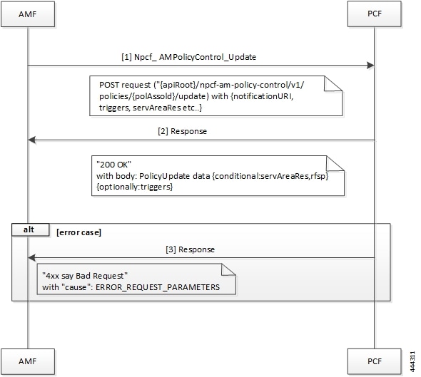
Update Policy Association

This section describes the Update Policy Association call flow.

Figure 3. Update a Policy Association Call Flow
Table 4. Update a Policy Association Call Flow Description

Step

Description

1

When AMF is relocated and the new AMF instance prefers to maintain the policy association, the AMF sends the Npcf_ AMPolicyControl_Update request to PCF.

2

The PCF registers and subscribes to the triggers for the service area restriction changes and responds to AMF with the trigger details.

3

In case of registration failure, PCF responds to AMF with an error indicating that the request is not completed and details of the issue that caused the failure.

Delete Policy Association

This section describes the Delete Policy Association call flow.

Figure 4. Delete Policy Association Call Flow
Table 5. Delete Policy Association Call Flow Description

Step

Description

1

In a situation where a policy association must be deleted, the UE sends a Deregistration request to AMF.

2

The AMF sends a Npcf_AMPolicyControl_Delete request to PCF.

3

On successful deletion, PCF sends a response to AMF with the confirmation.

4

In case the deletion was unsuccessful, PCF responds to AMF with an error indicating the deletion failure and the appropriate cause.

Terminate Policy Association

This section describes the Terminate Policy Association call flow.

Figure 5. Terminate Policy Association Call Flow
Table 6. Terminate Policy Association Call Flow Description

Step

Description

1

When PCF terminates the policy association, it initiates a terminate notification by sending the Npcf_ AMPolicyControl_UpdateNotify request to AMF.

2

The AMF responds to PCF with the confirmation indicating that Npcf_AMPolicyControl_Delete is initiated. Depending on the termination notification, AMF removes the policy association and initiates delete request.

3

In case the update policy enforcement was unsuccessful, the AMF redirects the subsequent notification to the new AMF.

4

In case of 404 error, AMF responds to PCF stating that it must search for a new URI using the IPv4 or IPv6 address, or refrain from sending notifications to the original AMF.

Update Notification Call Flow

This section describes the Update Notification call flow.

Figure 6. Update Notification Call Flow
Table 7. Update Notification Call Flow Description

Step

Description

1

When PCF must change the policy, it initiates an update notification by sending the Npcf_ AMPolicyControl_UpdateNotify request to AMF.

2

The AMF responds to PCF with the confirmation indicating that update policy is enforced.

3

In case the update policy enforcement was unsuccessful, the AMF redirects the subsequent notification to the new AMF.

4

In case of 404 error, AMF responds to PCF stating that it must search for a new URI using the IPv4 or IPv6 address, or refrain from sends notifications to the original AMF.

Standards Compliance

This feature complies with the following standards specifications:

  • 3GPP TS 29.510 Release 15.2.0 December 2018 "Network Function Repository Services"

  • 3GPP TS 29.571 [11] "Common Data Types for Service Based Interfaces"

Limitations

This feature has the following limitations in this release:

  • The PCF does not support PRA_CH trigger and related use cases.

Configuration Support for the N15 Access and Mobility Policies

This section describes how to configure the N15 access and mobility policies using the following services:

  1. Configure the N15 interface using the information documented at Configuring the REST Endpoints.

  2. Configuring the N15 Policy Service

    • Configuring the N15 Policy Retrievers

    • Configuring the N15 Policy Triggers

Configuring the N15 Policy Service

This section describes the parameters for the N15 policy configuration.

The N15 policy service configuration object is used to configure the Service Area Restriction capability. The configuration involves mapping the N15 policy attributes and the Service Area Restriction CRD table that derives data from the bilateral exchange of requests between AMF and PCF. A one-to-many relation is supported between this service configuration object and the associated CRD table.

Before configuring the N15 policy service, ensure that you have created the use case template and added the required service.

For information on how to create a use case template and add a service for this configuration, see Configuring the Use Case Template and Adding a Service.

Table 8. N15 Policy Parameters

Parameters

Description

Priority

Indicates the priority of the message for processing. The higher the number, the higher the priority. Default for most settings: 0

RAT Frequency Selection Priority

Indicates the "rfsp" attributes that PCF receives in the request.

The Radio Access Network (RAN) uses this parameter to derive the UE-specific cell reselection priorities to control the idle mode camping, and to decide on redirecting the active mode UEs to different frequency layers or RATs.

UE Policy

The UE policy consists of the UE Access Network discovery and selection policies.

Area Code

The area code is required only when the TAC information is unavailable. This code is operator-specific.

Tac Value

TACs are required only when the area code is unavailable.

Indicates a tracking area code that has a hexadecimal representation. Each character in the string shall take a value of "0" to "9" or "A" to "F" and represents 4 bits. The most significant character representing the 4 most significant bits of the TAC shall appear first in the string, and the character representing the 4 least significant bit of the TAC appears last in the string.

Examples:

A legacy TAC 0x4305 is encoded as "4305".

An extended TAC 0x63F84B is encoded as "63F84B"

Restriction Type

Provides the options to configure the type of restriction attribute that you want to configure:

  • ALLOWED_AREAS: Indicates the area where the restriction can be applied.

  • NOT_ALLOWED_AREAS: Indicates the area where the restriction cannot be applied.

  • NO_RESTRICTION: Indicates the areas that do not have any restriction applied.

Max Num Of T As

Denotes the maximum number of allowed tracking areas for use when the restriction is set to "ALLOWED_AREAS".

This attribute is unavailable when the Restriction Type takes the value as "NOT_ALLOWED_AREAS".

Note 
The Max Num Of T As value cannot be lower than the number of TAIs included in the "tacs" attribute.

Max Num Of T As For Not Allowed Areas

Denotes the maximum number of allowed tracking areas for use when Restriction Type is set to "NOT_ALLOWED_AREAS".

This attribute is unavailable when the Restriction Type takes the value as "ALLOWED_AREAS".

Configuring the N15 Policy Triggers

This section describes how to configure the N15 policy event triggers.

You can configure the event triggers through the Custom Reference Data (CRD) table. The triggers are a group of conditions used to evaluate a table. PCF subscribes to the configured triggers from the AMF. When the configured triggers are violated, AMF notifies PCF and sends the trigger information.

To configure the N15 policy event triggers, use the following configuration:

  1. Log in to Policy Builder.

  2. Click the Reference Data tab.

  3. In the left pane, choose Custom Reference Data Tables > Custom Reference Data Triggers.

  4. Select the service for which you want to create the trigger.

  5. In the right pane, enter the following trigger parameter:

    Parameter

    Description

    Priority

    Indicates the priority of the event triggers that must be used in case multiple service initiator conditions match.

    Trigger

    Specifies the trigger against which the N15 policy object is evaluated.

    You can configure the following triggers:

    • LOC_CH: Location change. This trigger is issued when the tracking area of the UE is changed.

    • RFSP_CH: Change in the RAT Frequency Selection Priority. The UDM notifies the AMF when the subscribed RFSP index is changed.

    • SERV_AREA_CH: Change in the Service Area Restrictions. The UDM notifies the AMF when the subscribed service area restriction information has modified.

Configuring the N15 Policy Retrievers

This section describes how to configure the retrievers for the N15 policy configuration object.

You can add the retrievers through the CRD table or Service Configuration.

For information on how to add the retrievers through CRD, see Configuring Retrievers through Custom Reference Data Table.

For information on how to add the retrievers through Service Configuration pane, see Configuring Retrievers through Service Configuration.

You can configure the following parameters under N15 policy retrievers:

  • N15 Access Type

  • N15 AMF Id

  • N15 AreaCode

  • N15 Cell Global Identifier

  • N15 GPSI

  • N15 GroupID

  • N15 MaxNumOfTAs

  • N15 MaxNumOfTAsForNotAllowedAreas

  • N15 MCC (SUPI Based)

  • N15 MNC (SUPI Based)

  • N15 Permanent Equipment Identifier

  • N15 RAT Type

  • N15 Restriction Type

  • N15 Serving Plmn

  • N15 ServiveName

  • N15 SliceInformation

  • N15 SUPI

  • N15 Tracking Area Identifier

Configuring the Stale Session Timer

This section describes how to configure the stale session timer.

Stale session builds up due to events such as network and timeout issues. As a result, PCF starts rejecting new sessions due to capacity or session license limit. The stale session timer configuration lets you set a timer after which PCF revalidates the stale sessions by sending a N7Notify request. If the N7Notify request gets an error response with code 404, then the session is deleted.

To configure the stale session timer for N7 and N15, use the following configuration:

  1. Log in into Policy Builder.

  2. Select Reference Data tab.

  3. From the left pane, select Systems.

  4. Select and expand your system name.

  5. Select PCF Configuration.

  6. In the right pane, configure the following parameters depending on the interface:

    Parameter

    Description

    N7 Stale Session Timer in Minutes

    The stale session maps to a session that is not available on the peer.

    The configured timeout value determines the duration for which a N7 session can remain idle before PCF revalidates it using the N7Notify request. If the response returned for the request contains an error code 404, then the session gets deleted.

    Default value is 180 minutes.

    Note 

    The stale session timer value should be less than the session expiration time. For information on how to configure the session expiration hours/minutes, see Adding a System.

    N15 Stale Session Timer in Minutes

    The stale session maps to a session that is not available on the peer.

    The configured timeout value determines the duration for which a N15 session can remain idle before PCF revalidates it using the N7Notify request. If the response returned for the request contains an error code 404, then the session gets deleted.

    Default value is 180 minutes.

    Note 

    The stale session timer value should be less than the session expiration time. For information on how to configure the session expiration hours/minutes, see Adding a System.

    Preferred Bit Rate

    Defines the value of the bitrate that is sent in the N7 policies. The bitrate is automatically converted as per the configured preferred bitrate.

Removing Stale Sessions

This section describes how to remove stale sessions for an SMF instance.

When the SMF issuing the sessions is unavailable, the sessions become stale after a period of inactivity. These sessions expire based on the duration that you defined in the Stale Session Timer configuration. In the case of a large number of sessions, the system takes longer to delete the session.


Important

We recommend removing the stale sessions only when SMF is unavailable. If SMF is active and has active sessions on PCF, then executing the cdl clear sessions command may remove the active sessions.


To delete the sessions in bulk, use the following command:

cdl clear sessions filter { key smfInstanceIdKey:SMF_instance_ip_address condition match } 

NOTES:

  • The cdl clear sessions command performs a hard delete of the sessions without generating termination request for the child sessions such as Rx and N28 sessions.

  • SMF_instance_ip_address —Specify the instance ID of SMF, which is derived from the notification URL sent by the SMF.