- Information About ASA Clustering
- How the ASA Cluster Fits into Your Network
- Performance Scaling Factor
- Cluster Members
- Cluster Interfaces
- Cluster Control Link
- High Availability Within the ASA Cluster
- Configuration Replication
- ASA Cluster Management
- Load Balancing Methods
- Inter-Site Clustering
- How the ASA Cluster Manages Connections
- ASA Features and Clustering
ASA Cluster
Clustering lets you group multiple ASAs together as a single logical device. A cluster provides all the convenience of a single device (management, integration into a network) while achieving the increased throughput and redundancy of multiple devices.

Note![]() Some features are not supported when using clustering. See Unsupported Features.
Some features are not supported when using clustering. See Unsupported Features.
- Information About ASA Clustering
- Licensing Requirements for ASA Clustering
- Prerequisites for ASA Clustering
- Guidelines and Limitations
- Default Settings
- Configuring ASA Clustering
- Managing ASA Cluster Members
- Monitoring the ASA Cluster
- Configuration Examples for ASA Clustering
- Feature History for ASA Clustering
Information About ASA Clustering
- How the ASA Cluster Fits into Your Network
- Performance Scaling Factor
- Cluster Members
- Cluster Interfaces
- Cluster Control Link
- High Availability Within the ASA Cluster
- Configuration Replication
- ASA Cluster Management
- Load Balancing Methods
- Inter-Site Clustering
- How the ASA Cluster Manages Connections
- ASA Features and Clustering
How the ASA Cluster Fits into Your Network
The cluster consists of multiple ASAs acting as a single unit. (See Licensing Requirements for ASA Clustering for the number of units supported per model). To act as a cluster, the ASAs need the following infrastructure:
- Isolated, high-speed backplane network for intra-cluster communication, known as the cluster control link. See Cluster Control Link.
- Management access to each ASA for configuration and monitoring. See ASA Cluster Management.
When you place the cluster in your network, the upstream and downstream routers need to be able to load-balance the data coming to and from the cluster using one of the following methods:
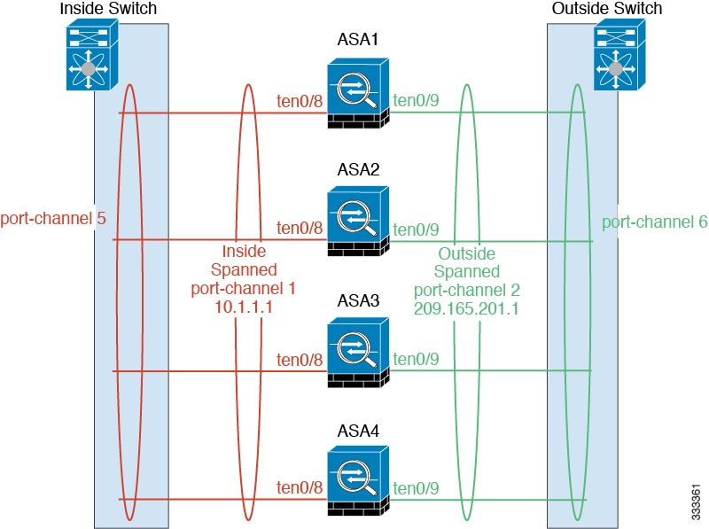
- Spanned EtherChannel (Recommended)—Interfaces on multiple members of the cluster are grouped into a single EtherChannel; the EtherChannel performs load balancing between units. See Spanned EtherChannel (Recommended).
- Policy-Based Routing (Routed firewall mode only)—The upstream and downstream routers perform load balancing between units using route maps and ACLs. See Policy-Based Routing (Routed Firewall Mode Only).
- Equal-Cost Multi-Path Routing (Routed firewall mode only)—The upstream and downstream routers perform load balancing between units using equal cost static or dynamic routes. See Equal-Cost Multi-Path Routing (Routed Firewall Mode Only).
Performance Scaling Factor
When you combine multiple units into a cluster, you can expect a performance of approximately:
For example, for throughput, the ASA 5585-X with SSP-40 can handle approximately 10 Gbps of real world firewall traffic when running alone. For a cluster of 8 units, the maximum combined throughput will be approximately 70% of 80 Gbps (8 units x 10 Gbps): 56 Gbps.
Cluster Members
ASA Hardware and Software Requirements
- Must be the same model with the same DRAM. You do not have to have the same amount of flash memory.
- Must run the identical software except at the time of an image upgrade. Hitless upgrade is supported. See Upgrade Path.
- You can have cluster members in different geographical locations (inter-site) when using individual interface mode. See Inter-Site Clustering for more information.
- Must be in the same security context mode, single or multiple.
- (Single context mode) Must be in the same firewall mode, routed or transparent.
- New cluster members must use the same SSL encryption setting (the ssl encryption command) as the master unit for initial cluster control link communication before configuration replication.
- Must have the same cluster, encryption and, for the ASA 5585-X, 10 GE I/O licenses.
Bootstrap Configuration
On each device, you configure a minimal bootstrap configuration including the cluster name, cluster control link interface, and other cluster settings. The first unit on which you enable clustering typically becomes the master unit. When you enable clustering on subsequent units, they join the cluster as slaves.
Master and Slave Unit Roles
One member of the cluster is the master unit. The master unit is determined by the priority setting in the bootstrap configuration; the priority is set between 1 and 100, where 1 is the highest priority. All other members are slave units. Typically, when you first create a cluster, the first unit you add becomes the master unit simply because it is the only unit in the cluster so far.
You must perform all configuration (aside from the bootstrap configuration) on the master unit only; the configuration is then replicated to the slave units. In the case of physical assets, such as interfaces, the configuration of the master unit is mirrored on all slave units. For example, if you configure GigabitEthernet 0/1 as the inside interface and GigabitEthernet 0/0 as the outside interface, then these interfaces are also used on the slave units as inside and outside interfaces.
Some features do not scale in a cluster, and the master unit handles all traffic for those features. See Centralized Features.
Master Unit Election
Members of the cluster communicate over the cluster control link to elect a master unit as follows:
1.![]() When you enable clustering for a unit (or when it first starts up with clustering already enabled), it broadcasts an election request every 3 seconds.
When you enable clustering for a unit (or when it first starts up with clustering already enabled), it broadcasts an election request every 3 seconds.
2.![]() Any other units with a higher priority respond to the election request; the priority is set between 1 and 100, where 1 is the highest priority.
Any other units with a higher priority respond to the election request; the priority is set between 1 and 100, where 1 is the highest priority.
3.![]() If after 45 seconds, a unit does not receive a response from another unit with a higher priority, then it becomes master.
If after 45 seconds, a unit does not receive a response from another unit with a higher priority, then it becomes master.
Note![]() If multiple units tie for the highest priority, the cluster unit name and then the serial number is used to determine the master.
If multiple units tie for the highest priority, the cluster unit name and then the serial number is used to determine the master.
4.![]() If a unit later joins the cluster with a higher priority, it does not automatically become the master unit; the existing master unit always remains as the master unless it stops responding, at which point a new master unit is elected.
If a unit later joins the cluster with a higher priority, it does not automatically become the master unit; the existing master unit always remains as the master unless it stops responding, at which point a new master unit is elected.
Note![]() You can manually force a unit to become the master. For centralized features, if you force a master unit change, then all connections are dropped, and you have to re-establish the connections on the new master unit. See Centralized Features for a list of centralized features.
You can manually force a unit to become the master. For centralized features, if you force a master unit change, then all connections are dropped, and you have to re-establish the connections on the new master unit. See Centralized Features for a list of centralized features.
Cluster Interfaces
You can configure data interfaces as either Spanned EtherChannels or as Individual interfaces. All data interfaces in the cluster must be one type only.
Interface Types
You can group one or more interfaces per unit into an EtherChannel that spans all units in the cluster. The EtherChannel aggregates the traffic across all the available active interfaces in the channel. A Spanned EtherChannel can be configured in both routed and transparent firewall modes. In routed mode, the EtherChannel is configured as a routed interface with a single IP address. In transparent mode, the IP address is assigned to the bridge group, not to the interface. The EtherChannel inherently provides load balancing as part of basic operation. See also the Spanned EtherChannel (Recommended).
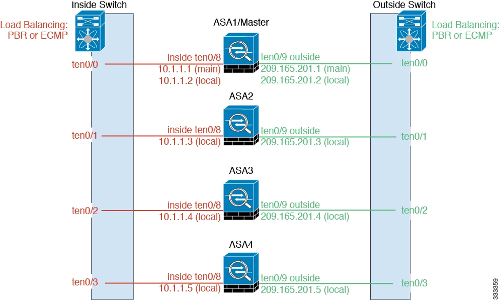
Individual interfaces are normal routed interfaces, each with their own Local IP address. Because interface configuration must be configured only on the master unit, the interface configuration lets you set a pool of IP addresses to be used for a given interface on the cluster members, including one for the master. The Main cluster IP address is a fixed address for the cluster that always belongs to the current master unit. The Main cluster IP address is a secondary IP address for the master unit; the Local IP address is always the primary address for routing. The Main cluster IP address provides consistent management access to an address; when a master unit changes, the Main cluster IP address moves to the new master unit, so management of the cluster continues seamlessly. Load balancing, however, must be configured separately on the upstream switch in this case. For information about load balancing, see Load Balancing Methods.
Note![]() We recommend Spanned EtherChannels instead of Individual interfaces because Individual interfaces rely on routing protocols to load-balance traffic, and routing protocols often have slow convergence during a link failure.
We recommend Spanned EtherChannels instead of Individual interfaces because Individual interfaces rely on routing protocols to load-balance traffic, and routing protocols often have slow convergence during a link failure.
Interface Type Mode
You must choose the interface type (Spanned EtherChannel or Individual) before you configure your devices. See the following guidelines for the interface type mode:
- You can always configure the management-only interface as an Individual interface (recommended), even in Spanned EtherChannel mode. The management interface can be an Individual interface even in transparent firewall mode.
- In Spanned EtherChannel mode, if you configure the management interface as an Individual interface, you cannot enable dynamic routing for the management interface. You must use a static route.
- In multiple context mode, you must choose one interface type for all contexts. For example, if you have a mix of transparent and routed mode contexts, you must use Spanned EtherChannel mode for all contexts because that is the only interface type allowed for transparent mode.
Cluster Control Link
Each unit must dedicate at least one hardware interface as the cluster control link.
Cluster Control Link Traffic Overview
Cluster control link traffic includes both control and data traffic.
- Master election. (See Cluster Members.)
- Configuration replication. (See Configuration Replication.)
- Health monitoring. (See Unit Health Monitoring.)
- State replication. (See Data Path Connection State Replication.)
- Connection ownership queries and data packet forwarding. (See Rebalancing New TCP Connections Across the Cluster.)
Cluster Control Link Interfaces and Network
You can use any data interface(s) for the cluster control link, with the following exceptions:
- You cannot use a VLAN subinterface as the cluster control link.
- You cannot use a Management x / x interface as the cluster control link, either alone or as an EtherChannel.
- For the ASA 5585-X with an ASA IPS module, you cannot use the module interfaces for the cluster control link; you can, however, use interfaces on the ASA 5585-X Network Module.
You can use an EtherChannel or redundant interface; see Cluster Control Link Redundancy for more information.
For the ASA 5585-X with SSP-10 and SSP-20, which include two Ten Gigabit Ethernet interfaces, we recommend using one interface for the cluster control link, and the other for data (you can use subinterfaces for data). Although this setup does not accommodate redundancy for the cluster control link, it does satisfy the need to size the cluster control link to match the size of the data interfaces. See Sizing the Cluster Control Link for more information.
Each cluster control link has an IP address on the same subnet. This subnet should be isolated from all other traffic, and should include only the ASA cluster control link interfaces.
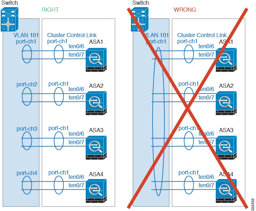
For a 2-member cluster, do not directly-connect the cluster control link from one ASA to the other ASA. If you directly connect the interfaces, then when one unit fails, the cluster control link fails, and thus the remaining healthy unit fails. If you connect the cluster control link through a switch, then the cluster control link remains up for the healthy unit.
Sizing the Cluster Control Link
You should size the cluster control link to match the expected throughput of each member. For example, if you have the ASA 5585-X with SSP-60, which can pass 14 Gbps per unit maximum in a cluster, then you should also assign interfaces to the cluster control link that can pass at least 14 Gbps. In this case, you could use 2 Ten Gigabit Ethernet interfaces in an EtherChannel for the cluster control link, and use the rest of the interfaces as desired for data links.
Cluster control link traffic is comprised mainly of state update and forwarded packets. The amount of traffic at any given time on the cluster control link varies. For example state updates could consume up to 10% of the through traffic amount if through traffic consists exclusively of short-lived TCP connections. The amount of forwarded traffic depends on the load-balancing efficacy or whether there is a lot of traffic for centralized features. For example:
- NAT results in poor load balancing of connections, and the need to rebalance all returning traffic to the correct units.
- AAA for network access is a centralized feature, so all traffic is forwarded to the master unit.
- When membership changes, the cluster needs to rebalance a large number of connections, thus temporarily using a large amount of cluster control link bandwidth.
A higher-bandwidth cluster control link helps the cluster to converge faster when there are membership changes and prevents throughput bottlenecks.
Note![]() If your cluster has large amounts of asymmetric (rebalanced) traffic, then you should increase the cluster control link size.
If your cluster has large amounts of asymmetric (rebalanced) traffic, then you should increase the cluster control link size.
For inter-site clusters and sizing the data center interconnect for cluster control link traffic, see Inter-Site Clustering.
Cluster Control Link Redundancy
We recommend using an EtherChannel for the cluster control link, so that you can pass traffic on multiple links in the EtherChannel while still achieving redundancy.
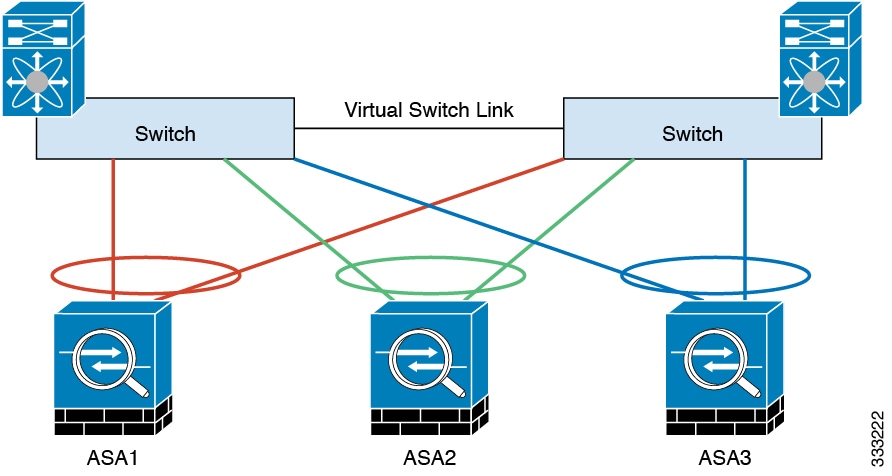
The following diagram shows how to use an EtherChannel as a cluster control link in a Virtual Switching System (VSS) or Virtual Port Channel (vPC) environment. All links in the EtherChannel are active. When the switch is part of a VSS or vPC, then you can connect ASA interfaces within the same EtherChannel to separate switches in the VSS or vPC. The switch interfaces are members of the same EtherChannel port-channel interface, because the separate switches act like a single switch. Note that this EtherChannel is device-local, not a Spanned EtherChannel.
Cluster Control Link Reliability
To ensure cluster control link functionality, be sure the round-trip time (RTT) between units is less than 20 ms. This maximum latency enhances compatibility with cluster members installed at different geographical sites. To check your latency, perform a ping on the cluster control link between units.
The cluster control link must be reliable, with no out-of-order or dropped packets; for example, for inter-site deployment, you should use a dedicated link.
Cluster Control Link Failure
If the cluster control link line protocol goes down for a unit, then clustering is disabled; data interfaces are shut down. After you fix the cluster control link, you must manually rejoin the cluster by re-enabling clustering; see Rejoining the Cluster.
Note![]() When an ASA becomes inactive, all data interfaces are shut down; only the management-only interface can send and receive traffic. The management interface remains up using the IP address the unit received from the cluster IP pool. However if you reload, and the unit is still inactive in the cluster, the management interface is not accessible (because it then uses the Main IP address, which is the same as the master unit). You must use the console port for any further configuration.
When an ASA becomes inactive, all data interfaces are shut down; only the management-only interface can send and receive traffic. The management interface remains up using the IP address the unit received from the cluster IP pool. However if you reload, and the unit is still inactive in the cluster, the management interface is not accessible (because it then uses the Main IP address, which is the same as the master unit). You must use the console port for any further configuration.
High Availability Within the ASA Cluster
Unit Health Monitoring
The master unit monitors every slave unit by sending keepalive messages over the cluster control link periodically (the period is configurable). Each slave unit monitors the master unit using the same mechanism.
Interface Monitoring
Each unit monitors the link status of all hardware interfaces in use (up or down), and reports status changes to the master unit.
- Spanned EtherChannel—Uses cluster Link Aggregation Control Protocol (cLACP). Each unit monitors the link status and the cLACP protocol messages to determine if the port is still active in the EtherChannel. The status is reported to the master unit.
- Individual interfaces (Routed mode only)—Each unit self-monitors its interfaces and reports interface status to the master unit.
Unit or Interface Failure
When health monitoring is enabled, a unit is removed from the cluster if it fails or if its interfaces fail. If an interface fails on a particular unit, but the same interface is active on other units, then the unit is removed from the cluster. The amount of time before the ASA removes a member from the cluster depends on the type of interface and whether the unit is an established member or is joining the cluster. For EtherChannels (spanned or not), if the interface is down on an established member, then the ASA removes the member after 9 seconds. If the unit is joining the cluster as a new member, the ASA waits 45 seconds before rejecting the new unit. For non-EtherChannels, the unit is removed after 500 ms, regardless of the member state.
When a unit in the cluster fails, the connections hosted by that unit are seamlessly transferred to other units; state information for traffic flows is shared over the control cluster link.
If the master unit fails, then another member of the cluster with the highest priority (lowest number) becomes the master.
The ASA automatically tries to rejoin the cluster; see Rejoining the Cluster.
Note![]() When an ASA becomes inactive and fails to automatically rejoin the cluster, all data interfaces are shut down; only the management-only interface can send and receive traffic. The management interface remains up using the IP address the unit received from the cluster IP pool. However if you reload, and the unit is still inactive in the cluster, the management interface is not accessible (because it then uses the Main IP address, which is the same as the master unit). You must use the console port for any further configuration.
When an ASA becomes inactive and fails to automatically rejoin the cluster, all data interfaces are shut down; only the management-only interface can send and receive traffic. The management interface remains up using the IP address the unit received from the cluster IP pool. However if you reload, and the unit is still inactive in the cluster, the management interface is not accessible (because it then uses the Main IP address, which is the same as the master unit). You must use the console port for any further configuration.
Rejoining the Cluster
After a cluster member is removed from the cluster, how it can rejoin the cluster depends on why it was removed:
- Failed cluster control link—After you resolve the problem with the cluster control link, you must manually rejoin the cluster by re-enabling clustering at the console port by entering cluster name, and then enable (see Configuring Basic Bootstrap Settings and Enabling Clustering).
- Failed data interface—The ASA automatically tries to rejoin at 5 minutes, then at 10 minutes, and finally at 20 minutes. If the join is not successful after 20 minutes, then the ASA disables clustering. After you resolve the problem with the data interface, you have to manually enable clustering at the console port by entering cluster name, and then enable (see Configuring Basic Bootstrap Settings and Enabling Clustering).
- Failed unit—If the unit was removed from the cluster because of a unit health check failure, then rejoining the cluster depends on the source of the failure. For example, a temporary power failure means the unit will rejoin the cluster when it starts up again as long as the cluster control link is up and clustering is still enabled with the enable command.
Data Path Connection State Replication
Every connection has one owner and at least one backup owner in the cluster. The backup owner does not take over the connection in the event of a failure; instead, it stores TCP/UDP state information, so that the connection can be seamlessly transferred to a new owner in case of a failure.
If the owner becomes unavailable, the first unit to receive packets from the connection (based on load balancing) contacts the backup owner for the relevant state information so it can become the new owner.
Some traffic requires state information above the TCP or UDP layer. See Table 9-1 for clustering support or lack of support for this kind of traffic.
|
|
|
|
|---|---|---|
Configuration Replication
All units in the cluster share a single configuration. Except for the initial bootstrap configuration, you can only make configuration changes on the master unit, and changes are automatically replicated to all other units in the cluster.
ASA Cluster Management
Management Network
We recommend connecting all units to a single management network. This network is separate from the cluster control link.
Management Interface
For the management interface, we recommend using one of the dedicated management interfaces. You can configure the management interfaces as Individual interfaces (for both routed and transparent modes) or as a Spanned EtherChannel interface.
We recommend using Individual interfaces for management, even if you use Spanned EtherChannels for your data interfaces. Individual interfaces let you connect directly to each unit if necessary, while a Spanned EtherChannel interface only allows remote connection to the current master unit.
Note![]() If you use Spanned EtherChannel interface mode, and configure the management interface as an Individual interface, you cannot enable dynamic routing for the management interface. You must use a static route.
If you use Spanned EtherChannel interface mode, and configure the management interface as an Individual interface, you cannot enable dynamic routing for the management interface. You must use a static route.
For an Individual interface, the Main cluster IP address is a fixed address for the cluster that always belongs to the current master unit. For each interface, you also configure a range of addresses so that each unit, including the current master, can use a Local address from the range. The Main cluster IP address provides consistent management access to an address; when a master unit changes, the Main cluster IP address moves to the new master unit, so management of the cluster continues seamlessly. The Local IP address is used for routing, and is also useful for troubleshooting.
For example, you can manage the cluster by connecting to the Main cluster IP address, which is always attached to the current master unit. To manage an individual member, you can connect to the Local IP address.
For outbound management traffic such as TFTP or syslog, each unit, including the master unit, uses the Local IP address to connect to the server.
For a Spanned EtherChannel interface, you can only configure one IP address, and that IP address is always attached to the master unit. You cannot connect directly to a slave unit using the EtherChannel interface; we recommend configuring the management interface as an Individual interface so that you can connect to each unit. Note that you can use a device-local EtherChannel for management.
Master Unit Management Vs. Slave Unit Management
Aside from the bootstrap configuration, all management and monitoring can take place on the master unit. From the master unit, you can check runtime statistics, resource usage, or other monitoring information of all units. You can also issue a command to all units in the cluster, and replicate the console messages from slave units to the master unit.
You can monitor slave units directly if desired. Although also available from the master unit, you can perform file management on slave units (including backing up the configuration and updating images). The following functions are not available from the master unit:
RSA Key Replication
When you create an RSA key on the master unit, the key is replicated to all slave units. If you have an SSH session to the Main cluster IP address, you will be disconnected if the master unit fails. The new master unit uses the same key for SSH connections, so that you do not need to update the cached SSH host key when you reconnect to the new master unit.
ASDM Connection Certificate IP Address Mismatch
By default, a self-signed certificate is used for the ASDM connection based on the Local IP address. If you connect to the Main cluster IP address using ASDM, then a warning message about a mismatched IP address appears because the certificate uses the Local IP address, and not the Main cluster IP address. You can ignore the message and establish the ASDM connection. However, to avoid this type of warning, you can enroll a certificate that contains the Main cluster IP address and all the Local IP addresses from the IP address pool. You can then use this certificate for each cluster member. For more information, see Chapter42, “Digital Certificates”
Load Balancing Methods
See also the Cluster Interfaces.
Spanned EtherChannel (Recommended)
You can group one or more interfaces per unit into an EtherChannel that spans all units in the cluster. The EtherChannel aggregates the traffic across all the available active interfaces in the channel.
Spanned EtherChannel Benefits
The EtherChannel method of load-balancing is recommended over other methods for the following benefits:
- Faster failure discovery.
- Faster convergence time. Individual interfaces rely on routing protocols to load-balance traffic, and routing protocols often have slow convergence during a link failure.
- Ease of configuration.
For more information about EtherChannels in general (not just for clustering), see EtherChannels.
Guidelines for Maximum Throughput
To achieve maximum throughput, we recommend the following:
- Use a load balancing hash algorithm that is “symmetric,” meaning that packets from both directions will have the same hash, and will be sent to the same ASA in the Spanned EtherChannel. We recommend using the source and destination IP address (the default) or the source and destination port as the hashing algorithm.
- Use the same type of line cards when connecting the ASAs to the switch so that hashing algorithms applied to all packets are the same.
Load Balancing
The EtherChannel link is selected using a proprietary hash algorithm, based on source or destination IP addresses and TCP and UDP port numbers.
Note![]() On the ASA, do not change the load-balancing algorithm from the default (see Customizing the EtherChannel). On the switch, we recommend that you use one of the following algorithms: source-dest-ip or source-dest-ip-port (see the Cisco Nexus OS or Cisco IOS port-channel load-balance command). Do not use a vlan keyword in the load-balance algorithm because it can cause unevenly distributed traffic to the ASAs in a cluster.
On the ASA, do not change the load-balancing algorithm from the default (see Customizing the EtherChannel). On the switch, we recommend that you use one of the following algorithms: source-dest-ip or source-dest-ip-port (see the Cisco Nexus OS or Cisco IOS port-channel load-balance command). Do not use a vlan keyword in the load-balance algorithm because it can cause unevenly distributed traffic to the ASAs in a cluster.
The number of links in the EtherChannel affects load balancing. See Load Balancing for more information.
Symmetric load balancing is not always possible. If you configure NAT, then forward and return packets will have different IP addresses and/or ports. Return traffic will be sent to a different unit based on the hash, and the cluster will have to redirect most returning traffic to the correct unit. See NAT for more information.
EtherChannel Redundancy
The EtherChannel has built-in redundancy. It monitors the line protocol status of all links. If one link fails, traffic is re-balanced between remaining links. If all links in the EtherChannel fail on a particular unit, but other units are still active, then the unit is removed from the cluster.
Connecting to a VSS or vPC
You can include multiple interfaces per ASA in the Spanned EtherChannel. Multiple interfaces per ASA are especially useful for connecting to both switches in a VSS or vPC.
Depending on your switches, you can configure up to 32 active links in the spanned EtherChannel. This feature requires both switches in the vPC to support EtherChannels with 16 active links each (for example the Cisco Nexus 7000 with F2-Series 10 Gigabit Ethernet Module).
For switches that support 8 active links in the EtherChannel, you can configure up to 16 active links in the spanned EtherChannel when connecting to two switches in a VSS/vPC.
If you want to use more than 8 active links in a spanned EtherChannel, you cannot also have standby links; the support for 9 to 32 active links requires you to disable cLACP dynamic port priority that allows the use of standby links. You can still use 8 active links and 8 standby links if desired, for example, when connecting to a single switch.
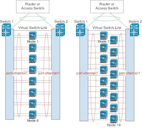
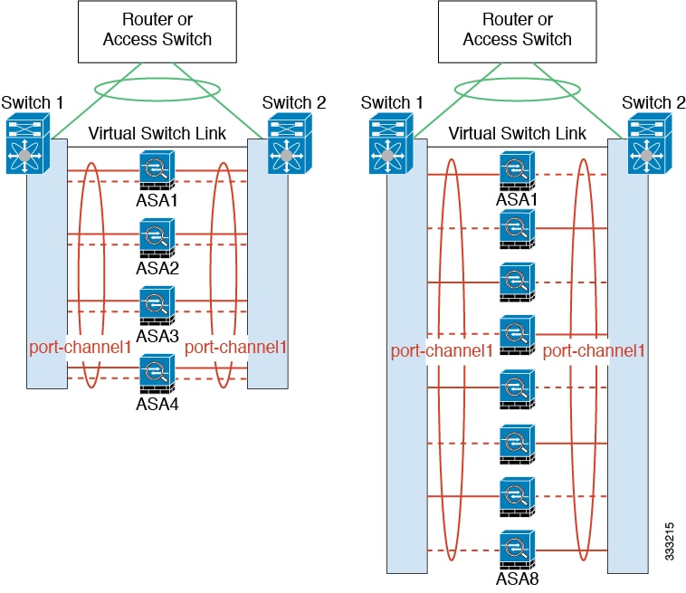
The following figure shows a 32 active link spanned EtherChannel in an 8-ASA cluster and a 16-ASA cluster.
The following figure shows a 16 active link spanned EtherChannel in a 4-ASA cluster and an 8-ASA cluster.
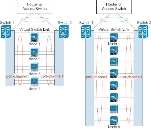
The following figure shows a traditional 8 active/8 standby link spanned EtherChannel in a 4-ASA cluster and an 8-ASA cluster. The active links are shown as solid lines, while the inactive links are dotted. cLACP load-balancing can automatically choose the best 8 links to be active in the EtherChannel. As shown, cLACP helps achieve load balancing at the link level.
Policy-Based Routing (Routed Firewall Mode Only)
When using Individual interfaces, each ASA interface maintains its own IP address and MAC address. One method of load balancing is Policy-Based Routing (PBR).
We recommend this method if you are already using PBR, and want to take advantage of your existing infrastructure. This method might offer additional tuning options vs. Spanned EtherChannel as well.
PBR makes routing decisions based on a route map and ACL. You must manually divide traffic between all ASAs in a cluster. Because PBR is static, it may not achieve the optimum load balancing result at all times. To achieve the best performance, we recommend that you configure the PBR policy so that forward and return packets of a connection are directed to the same physical ASA. For example, if you have a Cisco router, redundancy can be achieved by using Cisco IOS PBR with Object Tracking. Cisco IOS Object Tracking monitors each ASA using ICMP ping. PBR can then enable or disable route maps based on reachability of a particular ASA. See the following URLs for more details:
http://www.cisco.com/en/US/products/ps6599/products_white_paper09186a00800a4409.shtml
http://www.cisco.com/en/US/docs/ios/12_3t/12_3t4/feature/guide/gtpbrtrk.html#wp1057830
Note![]() If you use this method of load-balancing, you can use a device-local EtherChannel as an Individual interface.
If you use this method of load-balancing, you can use a device-local EtherChannel as an Individual interface.
Equal-Cost Multi-Path Routing (Routed Firewall Mode Only)
When using Individual interfaces, each ASA interface maintains its own IP address and MAC address. One method of load balancing is Equal-Cost Multi-Path (ECMP) routing.
We recommend this method if you are already using ECMP, and want to take advantage of your existing infrastructure. This method might offer additional tuning options vs. Spanned EtherChannel as well.
ECMP routing can forward packets over multiple “best paths” that tie for top place in the routing metric. Like EtherChannel, a hash of source and destination IP addresses and/or source and destination ports can be used to send a packet to one of the next hops. If you use static routes for ECMP routing, then an ASA failure can cause problems; the route continues to be used, and traffic to the failed ASA will be lost. If you use static routes, be sure to use a static route monitoring feature such as Object Tracking. We recommend using dynamic routing protocols to add and remove routes, in which case, you must configure each ASA to participate in dynamic routing.
Note![]() If you use this method of load-balancing, you can use a device-local EtherChannel as an Individual interface.
If you use this method of load-balancing, you can use a device-local EtherChannel as an Individual interface.
Inter-Site Clustering
Inter-Site Clustering Guidelines
See the following guidelines for inter-site clustering:
|
|
|
|
|---|---|---|
|
|
|
|
- The cluster control link latency must be less than 20 ms round-trip time (RTT).
- The cluster control link must be reliable, with no out-of-order or dropped packets; for example, you should use a dedicated link.
- Do not configure connection rebalancing (see Rebalancing New TCP Connections Across the Cluster); you do not want connections rebalanced to cluster members at a different site.
- The cluster implementation does not differentiate between members at multiple sites; therefore, connection roles for a given connection may span across sites (see Connection Roles). This is expected behavior.
- For transparent mode, you must ensure that both inside routers share the same MAC address, and also that both outside routers share the same MAC address. When a cluster member at site 1 forwards a connection to a member at site 2, the destination MAC address is preserved. The packet will only reach the router at site 2 if the MAC address is the same as the router at site 1.
- For transparent mode, do not extend the data VLANs between switches at each site; a loop will occur. Data traffic must be routed between the two sites.
Sizing the Data Center Interconnect
You should reserve bandwidth on the data center interconnect (DCI) for cluster control link traffic equivalent to the following calculation:

If the number of members differs at each site, use the larger number for your calculation. The minimum bandwidth for the DCI should not be less than the size of the cluster control link for one member.
–![]() 5 Gbps cluster control link per member
5 Gbps cluster control link per member
Reserved DCI bandwidth = 5 Gbps (2/2 x 5 Gbps).
–![]() 5 Gbps cluster control link per member
5 Gbps cluster control link per member
Reserved DCI bandwidth = 10 Gbps (4/2 x 5 Gbps).
–![]() 3 members at site 1, 2 members at site 2, and 1 member at site 3
3 members at site 1, 2 members at site 2, and 1 member at site 3
–![]() 10 Gbps cluster control link per member
10 Gbps cluster control link per member
Reserved DCI bandwidth = 15 Gbps (3/2 x 10 Gbps).
–![]() 10 Gbps cluster control link per member
10 Gbps cluster control link per member
Reserved DCI bandwidth = 10 Gbps (1/2 x 10 Gbps = 5 Gbps; but the minimum bandwidth should not be less than the size of the cluster control link (10 Gbps)).
Inter-Site Examples
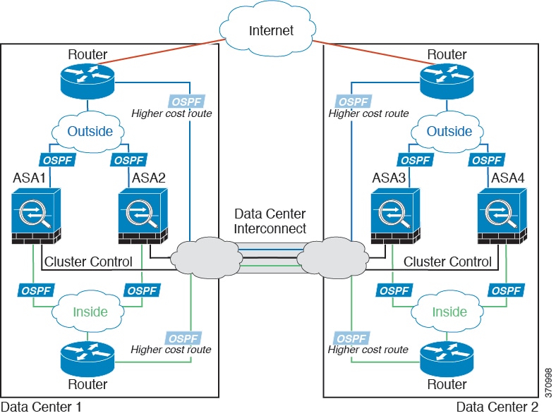
Individual Interface Inter-Site Example
The following example shows 2 ASA cluster members at each of 2 data centers. The cluster members are connected by the cluster control link over the DCI. The inside and outside routers at each data center use OSPF and PBR or ECMP to load balance the traffic between cluster members. By assigning a higher cost route across the DCI, traffic stays within each data center unless all ASA cluster members at a given site go down. In the event of a failure of all cluster members at one site, traffic goes from each router over the DCI to the ASA cluster members at the other site.
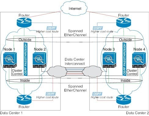
Spanned EtherChannel Transparent Mode Inter-Site Example
The following example shows 2 ASA cluster members at each of 2 data centers. The cluster members are connected by the cluster control link over the DCI. The cluster members at each site connect to the local switches using spanned EtherChannels for the inside and outside. The ASA EtherChannel is spanned across all ASAs in the cluster. The inside and outside routers at each data center use OSPF, which is passed through the transparent ASAs. Unlike MACs, router IPs are unique on all routers. By assigning a higher cost route across the DCI, traffic stays within each data center unless all ASA cluster members at a given site go down. The lower cost route through the ASAs must traverse the same bridge group at each site for the cluster to maintain asymmetric connections. the event of a failure of all cluster members at one site, traffic goes from each router over the DCI to the ASA cluster members at the other site.
The implementation of the switches at each site can include:
- Inter-site VSS/vPC—In this scenario, you install one switch at Data Center 1, and the other at Data Center 2. One option is for the ASA cluster units at each Data Center to only connect to the local switch, while the VSS/vPC traffic goes across the DCI. In this case, connections are for the most part kept local to each datacenter. You can optionally connect each ASA unit to both switches across the DCI if the DCI can handle the extra traffic. In this case, traffic is distributed across the data centers, so it is essential for the DCI to be very robust.
- Local VSS/vPC at each site—For better switch redundancy, you can install 2 separate VSS/vPC pairs at each site. In this case, although the ASAs still have a spanned EtherChannel with Data Center 1 ASAs connected only to both local switches, and Data Center 2 ASAs connected to those local switches, the spanned EtherChannel is essentially “split.” Each local VSS/vPC sees the spanned EtherChannel as a site-local EtherChannel.
How the ASA Cluster Manages Connections
Connection Roles
There are 3 different ASA roles defined for each connection:
- Owner—The unit that initially receives the connection. The owner maintains the TCP state and processes packets. A connection has only one owner.
- Director—The unit that handles owner lookup requests from forwarders and also maintains the connection state to serve as a backup if the owner fails. When the owner receives a new connection, it chooses a director based on a hash of the source/destination IP address and TCP ports, and sends a message to the director to register the new connection. If packets arrive at any unit other than the owner, the unit queries the director about which unit is the owner so it can forward the packets. A connection has only one director.
- Forwarder—A unit that forwards packets to the owner. If a forwarder receives a packet for a connection it does not own, it queries the director for the owner, and then establishes a flow to the owner for any other packets it receives for this connection. The director can also be a forwarder. Note that if a forwarder receives the SYN-ACK packet, it can derive the owner directly from a SYN cookie in the packet, so it does not need to query the director. (If you disable TCP sequence randomization, the SYN cookie is not used; a query to the director is required.) For short-lived flows such as DNS and ICMP, instead of querying, the forwarder immediately sends the packet to the director, which then sends them to the owner. A connection can have multiple forwarders; the most efficient throughput is achieved by a good load-balancing method where there are no forwarders and all packets of a connection are received by the owner.
New Connection Ownership
When a new connection is directed to a member of the cluster via load balancing, that unit owns both directions of the connection. If any connection packets arrive at a different unit, they are forwarded to the owner unit over the cluster control link. For best performance, proper external load balancing is required for both directions of a flow to arrive at the same unit, and for flows to be distributed evenly between units. If a reverse flow arrives at a different unit, it is redirected back to the original unit. For more information, see Load Balancing Methods.
Sample Data Flow
The following example shows the establishment of a new connection.
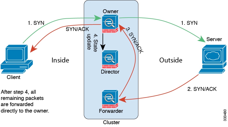
1.![]() The SYN packet originates from the client and is delivered to an ASA (based on the load balancing method), which becomes the owner. The owner creates a flow, encodes owner information into a SYN cookie, and forwards the packet to the server.
The SYN packet originates from the client and is delivered to an ASA (based on the load balancing method), which becomes the owner. The owner creates a flow, encodes owner information into a SYN cookie, and forwards the packet to the server.
2.![]() The SYN-ACK packet originates from the server and is delivered to a different ASA (based on the load balancing method). This ASA is the forwarder.
The SYN-ACK packet originates from the server and is delivered to a different ASA (based on the load balancing method). This ASA is the forwarder.
3.![]() Because the forwarder does not own the connection, it decodes owner information from the SYN cookie, creates a forwarding flow to the owner, and forwards the SYN-ACK to the owner.
Because the forwarder does not own the connection, it decodes owner information from the SYN cookie, creates a forwarding flow to the owner, and forwards the SYN-ACK to the owner.
4.![]() The owner sends a state update to the director, and forwards the SYN-ACK to the client.
The owner sends a state update to the director, and forwards the SYN-ACK to the client.
5.![]() The director receives the state update from the owner, creates a flow to the owner, and records the TCP state information as well as the owner. The director acts as the backup owner for the connection.
The director receives the state update from the owner, creates a flow to the owner, and records the TCP state information as well as the owner. The director acts as the backup owner for the connection.
6.![]() Any subsequent packets delivered to the forwarder will be forwarded to the owner.
Any subsequent packets delivered to the forwarder will be forwarded to the owner.
7.![]() If packets are delivered to any additional units, it will query the director for the owner and establish a flow.
If packets are delivered to any additional units, it will query the director for the owner and establish a flow.
8.![]() Any state change for the flow results in a state update from the owner to the director.
Any state change for the flow results in a state update from the owner to the director.
Rebalancing New TCP Connections Across the Cluster
If the load balancing capabilities of the upstream or downstream routers result in unbalanced flow distribution, you can configure overloaded units to redirect new TCP flows to other units. No existing flows will be moved to other units.
ASA Features and Clustering
Unsupported Features
These features cannot be configured with clustering enabled, and the commands will be rejected.
Centralized Features
The following features are only supported on the master unit, and are not scaled for the cluster. For example, you have a cluster of eight units (5585-X with SSP-60). The Other VPN license allows a maximum of 10,000 site-to-site IPsec tunnels for one ASA 5585-X with SSP-60. For the entire cluster of eight units, you can only use 10,000 tunnels; the feature does not scale.
Note![]() Traffic for centralized features is forwarded from member units to the master unit over the cluster control link; see Sizing the Cluster Control Link to ensure adequate bandwidth for the cluster control link.
Traffic for centralized features is forwarded from member units to the master unit over the cluster control link; see Sizing the Cluster Control Link to ensure adequate bandwidth for the cluster control link.
If you use the rebalancing feature (see Rebalancing New TCP Connections Across the Cluster), traffic for centralized features may be rebalanced to non-master units before the traffic is classified as a centralized feature; if this occurs, the traffic is then sent back to the master unit.
For centralized features, if the master unit fails, all connections are dropped, and you have to re-establish the connections on the new master unit.
- Dynamic routing (Spanned EtherChannel mode only)
- Multicast routing (Individual interface mode only)
- Static route monitoring
- IGMP multicast control plane protocol processing (data plane forwarding is distributed across the cluster)
- PIM multicast control plane protocol processing (data plane forwarding is distributed across the cluster)
- Authentication and Authorization for network access. Accounting is decentralized.
- Filtering Services
Features Applied to Individual Units
These features are applied to each ASA unit, instead of the cluster as a whole or to the master unit.
- QoS—The QoS policy is synced across the cluster as part of configuration replication. However, the policy is enforced on each unit independently. For example, if you configure policing on output, then the conform rate and conform burst values are enforced on traffic exiting a particular ASA. In a cluster with 8 units and with traffic evenly distributed, the conform rate actually becomes 8 times the rate for the cluster.
- Threat detection—Threat detection works on each unit independently; for example, the top statistics is unit-specific. Port scanning detection, for example, does not work because scanning traffic will be load-balanced between all units, and one unit will not see all traffic.
- Resource management—Resource management in multiple context mode is enforced separately on each unit based on local usage.
- ASA FirePOWER module—There is no configuration sync or state sharing between ASA FirePOWER modules. You are responsible for maintaining consistent policies on the ASA FirePOWER modules in the cluster using FireSIGHT Management Center. Do not use different ASA-interface-based zone definitions for devices in the cluster.
- ASA IPS module—There is no configuration sync or state sharing between IPS modules. Some IPS signatures require IPS to keep the state across multiple connections. For example, the port scanning signature is used when the IPS module detects that someone is opening many connections to one server but with different ports. In clustering, those connections will be balanced between multiple ASA devices, each of which has its own IPS module. Because these IPS modules do not share state information, the cluster may not be able to detect port scanning as a result.
Dynamic Routing
Note![]() BGP is not supported with clustering.
BGP is not supported with clustering.
Dynamic Routing in Spanned EtherChannel Mode
In Spanned EtherChannel mode, the routing process only runs on the master unit, and routes are learned through the master unit and replicated to slaves. If a routing packet arrives at a slave, it is redirected to the master unit.
Figure 9-1 Dynamic Routing in Spanned EtherChannel Mode
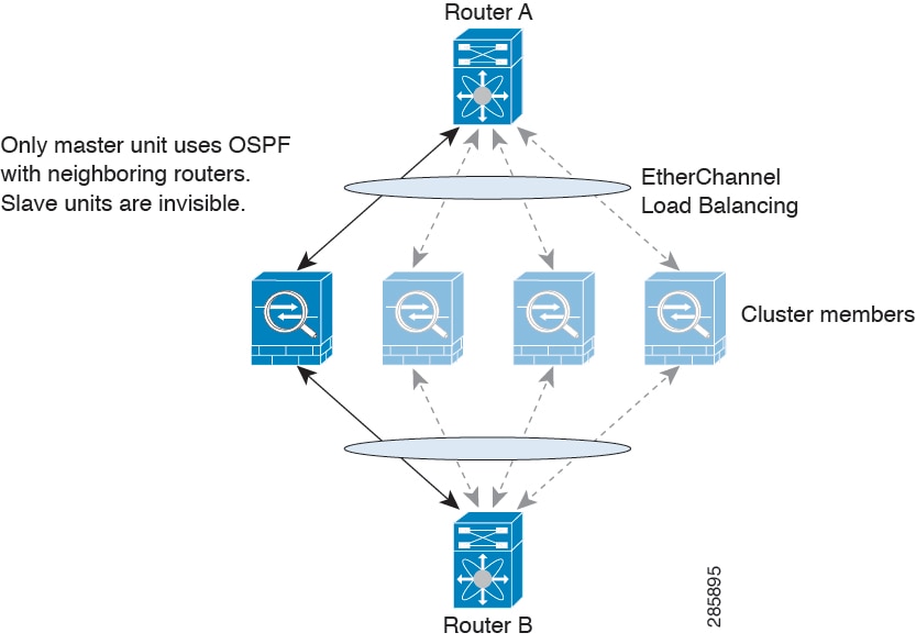
After the slave members learn the routes from the master unit, each unit makes forwarding decisions independently.
The OSPF LSA database is not synchronized from the master unit to slave units. If there is a master unit switchover, the neighboring router will detect a restart; the switchover is not transparent. The OSPF process picks an IP address as its router ID. Although not required, you can assign a static router ID to ensure a consistent router ID is used across the cluster.
Dynamic Routing in Individual Interface Mode
In Individual interface mode, each unit runs the routing protocol as a standalone router, and routes are learned by each unit independently.
Figure 9-2 Dynamic Routing in Individual Interface Mode
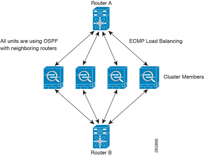
In the above diagram, Router A learns that there are 4 equal-cost paths to Router B, each through an ASA. ECMP is used to load balance traffic between the 4 paths. Each ASA picks a different router ID when talking to external routers.
You must configure a cluster pool for the router ID so that each unit has a separate router ID.
Multicast Routing
Multicast Routing in Spanned EtherChannel Mode
In Spanned EtherChannel mode, the master unit handles all multicast routing packets and data packets until fast-path forwarding is established. After the connection is established, each slave can forward multicast data packets.
Multicast Routing in Individual Interface Mode
In Individual interface mode, units do not act independently with multicast. All data and routing packets are processed and forwarded by the master unit, thus avoiding packet replication.
NAT
NAT can impact the overall throughput of the cluster. Inbound and outbound NAT packets can be sent to different ASAs in the cluster because the load balancing algorithm relies on IP addresses and ports, and NAT causes inbound and outbound packets to have different IP addresses and/or ports. When a packet arrives at an ASA that is not the connection owner, it is forwarded over the cluster control link to the owner, causing large amounts of traffic on the cluster control link.
If you still want to use NAT in clustering, then consider the following guidelines:
- No Proxy ARP—For Individual interfaces, a proxy ARP reply is never sent for mapped addresses. This prevents the adjacent router from maintaining a peer relationship with an ASA that may no longer be in the cluster. The upstream router needs a static route or PBR with Object Tracking for the mapped addresses that points to the Main cluster IP address. This is not an issue for a Spanned EtherChannel, because there is only one IP address associated with the cluster interface.
- No interface PAT on an Individual interface—Interface PAT is not supported for Individual interfaces.
- NAT pool address distribution for dynamic PAT—The master unit evenly pre-distributes addresses across the cluster. If a member receives a connection and they have no addresses left, the connection is dropped, even if other members still have addresses available. Make sure to include at least as many NAT addresses as there are units in the cluster to ensure that each unit receives an address. Use the show nat pool cluster command to see the address allocations.
- No round-robin—Round-robin for a PAT pool is not supported with clustering.
- Dynamic NAT xlates managed by the master unit—The master unit maintains and replicates the xlate table to slave units. When a slave unit receives a connection that requires dynamic NAT, and the xlate is not in the table, it requests the xlate from the master unit. The slave unit owns the connection.
- Per-session PAT feature—Although not exclusive to clustering, the per-session PAT feature improves the scalability of PAT and, for clustering, allows each slave unit to own PAT connections; by contrast, multi-session PAT connections have to be forwarded to and owned by the master unit. By default, all TCP traffic and UDP DNS traffic use a per-session PAT xlate. For traffic that requires multi-session PAT, such as H.323, SIP, or Skinny, you can disable per-session PAT. For more information about per-session PAT, see the firewall configuration guide.
- No static PAT for the following inspections—
AAA for Network Access
AAA for network access consists of three components: authentication, authorization, and accounting. Authentication and accounting are implemented as centralized features on the clustering master with replication of the data structures to the cluster slaves. If a master is elected, the new master will have all the information it needs to continue uninterrupted operation of the established authenticated users and their associated authorizations. Idle and absolute timeouts for user authentications are preserved when a master unit change occurs.
Accounting is implemented as a distributed feature in a cluster. Accounting is done on a per-flow basis, so the cluster unit owning a flow will send accounting start and stop messages to the AAA server when accounting is configured for a flow.
Syslog and NetFlow
- Syslog—Each unit in the cluster generates its own syslog messages. You can configure logging so that each unit uses either the same or a different device ID in the syslog message header field. For example, the hostname configuration is replicated and shared by all units in the cluster. If you configure logging to use the hostname as the device ID, syslog messages generated by all units look as if they come from a single unit. If you configure logging to use the local-unit name that is assigned in the cluster bootstrap configuration as the device ID, syslog messages look as if they come from different units. See Including the Device ID in Non-EMBLEM Format Syslog Messages.
- NetFlow—Each unit in the cluster generates its own NetFlow stream. The NetFlow collector can only treat each ASA as a separate NetFlow exporter.
SNMP
An SNMP agent polls each individual ASA by its Local IP address. You cannot poll consolidated data for the cluster.
You should always use the Local address, and not the Main cluster IP address for SNMP polling. If the SNMP agent polls the Main cluster IP address, if a new master is elected, the poll to the new master unit will fail.
VPN
Site-to-site VPN is a centralized feature; only the master unit supports VPN connections.
Note![]() Remote access VPN is not supported with clustering.
Remote access VPN is not supported with clustering.
VPN functionality is limited to the master unit and does not take advantage of the cluster high availability capabilities. If the master unit fails, all existing VPN connections are lost, and VPN users will see a disruption in service. When a new master is elected, you must reestablish the VPN connections.
When you connect a VPN tunnel to a Spanned EtherChannel address, connections are automatically forwarded to the master unit. For connections to an Individual interface when using PBR or ECMP, you must always connect to the Main cluster IP address, not a Local address.
VPN-related keys and certificates are replicated to all units.
FTP
- If FTP data channel and control channel flows are owned by different cluster members, the data channel owner will periodically send idle timeout updates to the control channel owner and update the idle timeout value. However, if the control flow owner is reloaded, and the control flow is re-hosted, the parent/child flow relationship will not longer be maintained; the control flow idle timeout will not be updated.
- If you use AAA for FTP access, then the control channel flow is centralized on the master unit.
Cisco TrustSec
Only the master unit learns security group tag (SGT) information. The master unit then populates the SGT to slaves, and slaves can make a match decision for SGT based on the security policy.
Licensing Requirements for ASA Clustering
Prerequisites for ASA Clustering
- Be sure to complete the switch configuration before you configure clustering on the ASAs.
- Table 9-2 lists supported external hardware and software to interoperate with ASA clustering.
|
|
|
|
|---|---|---|
–![]() Some switches do not support dynamic port priority with LACP (active and standby links). You can disable dynamic port priority to provide better compatibility with spanned EtherChannels.
Some switches do not support dynamic port priority with LACP (active and standby links). You can disable dynamic port priority to provide better compatibility with spanned EtherChannels.
–![]() Network elements on the cluster control link path should not verify the L4 checksum. Redirected traffic over the cluster control link does not have a correct L4 checksum. Switches that verify the L4 checksum could cause traffic to be dropped.
Network elements on the cluster control link path should not verify the L4 checksum. Redirected traffic over the cluster control link does not have a correct L4 checksum. Switches that verify the L4 checksum could cause traffic to be dropped.
–![]() Port-channel bundling downtime should not exceed the configured keepalive interval.
Port-channel bundling downtime should not exceed the configured keepalive interval.
–![]() See “Getting Started,” for more information about connecting to the ASA and setting the management IP address.
See “Getting Started,” for more information about connecting to the ASA and setting the management IP address.
–![]() Except for the IP address used by the master unit (typically the first unit you add to the cluster), these management IP addresses are for temporary use only.
Except for the IP address used by the master unit (typically the first unit you add to the cluster), these management IP addresses are for temporary use only.
–![]() After a slave joins the cluster, its management interface configuration is replaced by the one replicated from the master unit.
After a slave joins the cluster, its management interface configuration is replaced by the one replicated from the master unit.
- To use jumbo frames on the cluster control link (recommended), you must enable Jumbo Frame Reservation before you enable clustering. See Enabling Jumbo Frame Support.
- See also ASA Hardware and Software Requirements.
We recommend using a terminal server to access all cluster member unit console ports. For initial setup, and ongoing management (for example, when a unit goes down), a terminal server is useful for remote management.
Guidelines and Limitations
Supported in single and multiple context modes. The mode must match on each member unit.
Supported in routed and transparent firewall modes. For single mode, the firewall mode must match on all units.
Failover is not supported with clustering.
Supports IPv6. However, the cluster control link is only supported using IPv4.
For the ASA 5585-X with SSP-10 and SSP-20, which include two Ten Gigabit Ethernet interfaces, we recommend using one interface for the cluster control link, and the other for data (you can use subinterfaces for data). Although this setup does not accommodate redundancy for the cluster control link, it does satisfy the need to size the cluster control link to match the size of the data interfaces. See Sizing the Cluster Control Link for more information.
- On the switch(es) for the cluster control link interfaces, you can optionally enable Spanning Tree PortFast on the switch ports connected to the ASA to speed up the join process for new units.
- When you see slow bundling of a Spanned EtherChannel on the switch, you can enable LACP rate fast for an Individual interface on the switch.
- On the switch, we recommend that you use one of the following EtherChannel load-balancing algorithms: source-dest-ip or source-dest-ip-port (see the Cisco Nexus OS and Cisco IOS port-channel load-balance command). Do not use a vlan keyword in the load-balance algorithm because it can cause unevenly distributed traffic to the ASAs in a cluster. Do not change the load-balancing algorithm from the default on the ASA (in the port-channel load-balance command).
- If you change the load-balancing algorithm of the EtherChannel on the switch, the EtherChannel interface on the switch temporarily stops forwarding traffic, and the Spanning Tree Protocol restarts. There will be a delay before traffic starts flowing again.
- You should disable the LACP Graceful Convergence feature on all cluster-facing EtherChannel interfaces for Cisco Nexus switches.
- The ASA does not support connecting an EtherChannel to a switch stack. If the ASA EtherChannel is connected cross stack, and if the master switch is powered down, then the EtherChannel connected to the remaining switch will not come up.
- For detailed EtherChannel guidelines, limitations, and prerequisites, see Configuring an EtherChannel.
- See also the EtherChannel Guidelines.
- Spanned vs. Device-Local EtherChannel Configuration—Be sure to configure the switch appropriately for Spanned EtherChannels vs. Device-local EtherChannels.
–![]() Spanned EtherChannels—For ASA Spanned EtherChannels, which span across all members of the cluster, the interfaces are combined into a single EtherChannel on the switch. Make sure each interface is in the same channel group on the switch.
Spanned EtherChannels—For ASA Spanned EtherChannels, which span across all members of the cluster, the interfaces are combined into a single EtherChannel on the switch. Make sure each interface is in the same channel group on the switch.
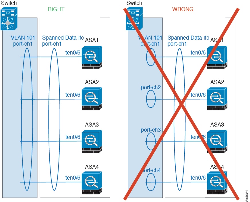
–![]() Device-local EtherChannels—For ASA Device-local EtherChannels including any EtherChannels configured for the cluster control link, be sure to configure discrete EtherChannels on the switch; do not combine multiple ASA EtherChannels into one EtherChannel on the switch.
Device-local EtherChannels—For ASA Device-local EtherChannels including any EtherChannels configured for the cluster control link, be sure to configure discrete EtherChannels on the switch; do not combine multiple ASA EtherChannels into one EtherChannel on the switch.
- See ASA Hardware and Software Requirements.
- For unsupported features with clustering, see Unsupported Features.
- When significant topology changes occur (such as adding or removing an EtherChannel interface, enabling or disabling an interface on the ASA or the switch, adding an additional switch to form a VSS or vPC) you should disable the health check feature. When the topology change is complete, and the configuration change is synced to all units, you can re-enable the health check feature.
- When adding a unit to an existing cluster, or when reloading a unit, there will be a temporary, limited packet/connection drop; this is expected behavior. In some cases, the dropped packets can hang your connection; for example, dropping a FIN/ACK packet for an FTP connection will make the FTP client hang. In this case, you need to reestablish the FTP connection.
- If you use a Windows 2003 server connected to a Spanned EtherChannel, when the syslog server port is down and the server does not throttle ICMP error messages, then large numbers of ICMP messages are sent back to the ASA cluster. These messages can result in some units of the ASA cluster experiencing high CPU, which can affect performance. We recommend that you throttle ICMP error messages.
Default Settings
- When using Spanned EtherChannels, the cLACP system ID is auto-generated and the system priority is 1 by default.
- The cluster health check feature is enabled by default with the holdtime of 3 seconds.
- Connection rebalancing is disabled by default. If you enable connection rebalancing, the default time between load information exchanges is 5 seconds.
Configuring ASA Clustering
Note![]() To enable or disable clustering, you must use a console connection (for CLI) or an ASDM connection.
To enable or disable clustering, you must use a console connection (for CLI) or an ASDM connection.
- Task Flow for ASA Cluster Configuration
- Cabling the Cluster Units and Configuring Upstream and Downstream Equipment
- Configuring the Cluster Interface Mode on Each Unit
- Configuring Interfaces on the Master Unit
- Configuring the Master Unit Bootstrap Settings
- Configuring Slave Unit Bootstrap Settings
Task Flow for ASA Cluster Configuration
To configure clustering, perform the following steps:
Step 1![]() Complete all pre-configuration on the switches and ASAs according to the Prerequisites for ASA Clustering.
Complete all pre-configuration on the switches and ASAs according to the Prerequisites for ASA Clustering.
Step 2![]() Cable your equipment. Before configuring clustering, cable the cluster control link network, management network, and data networks. See Cabling the Cluster Units and Configuring Upstream and Downstream Equipment.
Cable your equipment. Before configuring clustering, cable the cluster control link network, management network, and data networks. See Cabling the Cluster Units and Configuring Upstream and Downstream Equipment.
Step 3![]() Configure the interface mode. You can only configure one type of interface for clustering: Spanned EtherChannels or Individual interfaces. See Configuring the Cluster Interface Mode on Each Unit.
Configure the interface mode. You can only configure one type of interface for clustering: Spanned EtherChannels or Individual interfaces. See Configuring the Cluster Interface Mode on Each Unit.
Step 4![]() Configure interfaces for clustering on the master unit. You cannot enable clustering if the interfaces are not cluster-ready. See Configuring Interfaces on the Master Unit.
Configure interfaces for clustering on the master unit. You cannot enable clustering if the interfaces are not cluster-ready. See Configuring Interfaces on the Master Unit.
Step 5![]() Configure the bootstrap settings and enable clustering on the master unit. See Configuring the Master Unit Bootstrap Settings.
Configure the bootstrap settings and enable clustering on the master unit. See Configuring the Master Unit Bootstrap Settings.
Step 6![]() Configure the bootstrap settings for each slave unit. See Configuring Slave Unit Bootstrap Settings.
Configure the bootstrap settings for each slave unit. See Configuring Slave Unit Bootstrap Settings.
Step 7![]() Configure the security policy on the master unit. See the chapters in this guide to configure supported features on the master unit. The configuration is replicated to the slave units. For a list of supported and unsupported features, see ASA Features and Clustering.
Configure the security policy on the master unit. See the chapters in this guide to configure supported features on the master unit. The configuration is replicated to the slave units. For a list of supported and unsupported features, see ASA Features and Clustering.
Cabling the Cluster Units and Configuring Upstream and Downstream Equipment
Before configuring clustering, cable the cluster control link network, management network, and data networks.
Note![]() At a minimum, an active cluster control link network is required before you configure the units to join the cluster.
At a minimum, an active cluster control link network is required before you configure the units to join the cluster.
You should also configure the upstream and downstream equipment. For example, if you use EtherChannels, then you should configure the upstream and downstream equipment for the EtherChannels.
Examples
Note![]() This example uses EtherChannels for load-balancing. If you are using PBR or ECMP, your switch configuration will differ.
This example uses EtherChannels for load-balancing. If you are using PBR or ECMP, your switch configuration will differ.
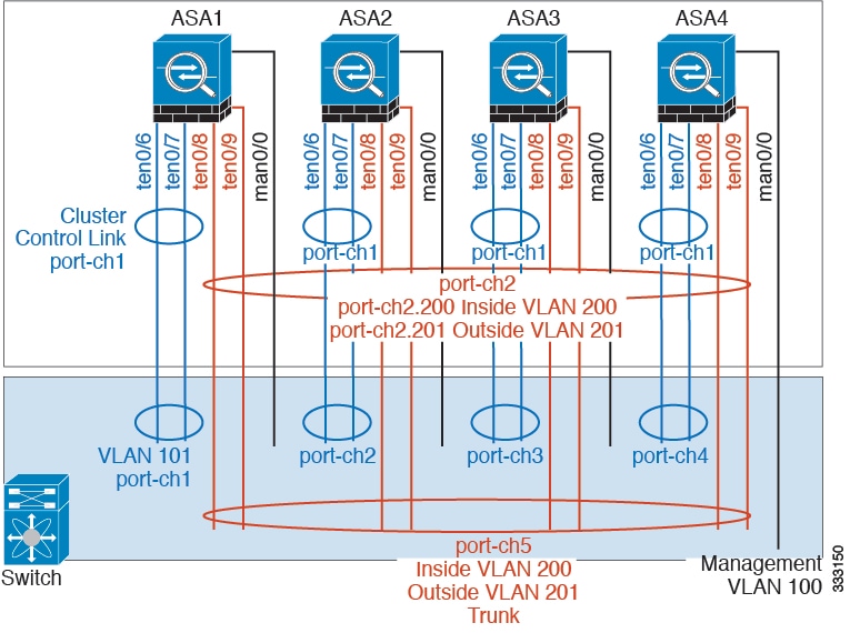
For example on each of 4 ASA 5585-Xs, you want to use:
- 2 Ten Gigabit Ethernet interfaces in a device-local EtherChannel for the cluster control link.
- 2 Ten Gigabit Ethernet interfaces in a Spanned EtherChannel for the inside and outside network; each interface is a VLAN subinterface of the EtherChannel. Using subinterfaces lets both inside and outside interfaces take advantage of the benefits of an EtherChannel.
- 1 Management interface.
You have one switch for both the inside and outside networks.
What to Do Next
Configure the cluster interface mode on each unit. See Configuring the Cluster Interface Mode on Each Unit.
Configuring the Cluster Interface Mode on Each Unit
You can only configure one type of interface for clustering: Spanned EtherChannels or Individual interfaces; you cannot mix interface types in a cluster. For exceptions for the management interface and other guidelines, see Interface Type Mode.
Prerequisites
Detailed Steps
What to Do Next
Configure interfaces. See Configuring Interfaces on the Master Unit.
Configuring Interfaces on the Master Unit
You must modify any interface that is currently configured with an IP address to be cluster-ready before you enable clustering. For other interfaces, you can configure them before or after you enable clustering; we recommend pre-configuring all of your interfaces so that the complete configuration is synced to new cluster members.
This section describes how to configure interfaces to be compatible with clustering. You can configure data interfaces as either Spanned EtherChannels or as Individual interfaces. Each method uses a different load-balancing mechanism. You cannot configure both types in the same configuration, with the exception of the management interface, which can be an Individual interface even in Spanned EtherChannel mode. For more information, see Cluster Interfaces.
Configuring Individual Interfaces (Recommended for the Management Interface)
Individual interfaces are normal routed interfaces, each with their own IP address taken from a pool of IP addresses. The Main cluster IP address is a fixed address for the cluster that always belongs to the current master unit.
In Spanned EtherChannel mode, we recommend configuring the management interface as an Individual interface. Individual management interfaces let you connect directly to each unit if necessary, while a Spanned EtherChannel interface only allows connection to the current master unit. See Management Interface for more information.
Prerequisites
- Except for the management-only interface, you must be in Individual interface mode; see Configuring the Cluster Interface Mode on Each Unit.
- For multiple context mode, perform this procedure in each context. If you are not already in the context configuration mode, enter the changeto context name command.
- Individual interfaces require you to configure load balancing on neighbor devices. External load balancing is not required for the management interface. For information about load balancing, see Load Balancing Methods.
- (Optional) Configure the interface as a device-local EtherChannel interface, a redundant interface, and/or configure subinterfaces.
–![]() For an EtherChannel, see Configuring an EtherChannel. This EtherChannel is local to the unit, and is not a Spanned EtherChannel.
For an EtherChannel, see Configuring an EtherChannel. This EtherChannel is local to the unit, and is not a Spanned EtherChannel.
–![]() For a redundant interface, see Configuring a Redundant Interface. Management-only interfaces cannot be redundant interfaces.
For a redundant interface, see Configuring a Redundant Interface. Management-only interfaces cannot be redundant interfaces.
–![]() For subinterfaces, see Configuring VLAN Subinterfaces and 802.1Q Trunking.
For subinterfaces, see Configuring VLAN Subinterfaces and 802.1Q Trunking.
Detailed Steps
|
|
|
|
|---|---|---|
| ip local pool poolname first-address — last-address [ mask mask ] ipv6 local pool poolname ipv6-address/prefix-length number_of_addresses ciscoasa(config)# ip local pool ins 192.168.1.2-192.168.1.9 ciscoasa(config-if)# ipv6 local pool insipv6 2001:DB8::1002/32 8 |
Configures a pool of Local IP addresses (IPv4 and/or IPv6), one of which will be assigned to each cluster unit for the interface. Include at least as many addresses as there are units in the cluster. If you plan to expand the cluster, include additional addresses. The Main cluster IP address that belongs to the current master unit is not a part of this pool; be sure to reserve an IP address on the same network for the Main cluster IP address. You cannot determine the exact Local address assigned to each unit in advance; to see the address used on each unit, enter the show ip [ v6 ] local pool poolname command. Each cluster member is assigned a member ID when it joins the cluster. The ID determines the Local IP used from the pool. |
|
|
|
||
|
|
Sets an interface to management-only mode so that it does not pass through traffic. By default, Management type interfaces are configured as management-only. In transparent mode, this command is always enabled for a Management type interface. This setting is required if the cluster interface mode is Spanned. |
|
|
|
The name is a text string up to 48 characters, and is not case-sensitive. You can change the name by reentering this command with a new value. |
|
| ip address ip_address [ mask ] cluster-pool poolname ipv6 address ipv6-address/prefix-length cluster-pool poolname ciscoasa(config-if)# ip address 192.168.1.1 255.255.255.0 cluster-pool ins ciscoasa(config-if)# ipv6 address 2001:DB8::1002/32 cluster-pool insipv6 |
Sets the Main cluster IP address and identifies the cluster pool. This IP address must be on the same network as the cluster pool addresses, but not be part of the pool. You can configure an IPv4 and/or an IPv6 address. DHCP, PPPoE, and IPv6 autoconfiguration are not supported; you must manually configure the IP addresses. |
|
|
|
Sets the security level, where number is an integer between 0 (lowest) and 100 (highest). See Security Levels. |
|
|
|
Examples
The following example configures the Management 0/0 and Management 0/1 interfaces as a device-local EtherChannel, and then configures the EtherChannel as an Individual interface:
ip local pool mgmt 10.1.1.2-10.1.1.9
ipv6 local pool mgmtipv6 2001:DB8:45:1002/64 8
What to Do Next
- For spanned interface mode, configure your data interfaces. See Configuring Spanned EtherChannels.
- For Individual interface mode, join the cluster. See Configuring the Master Unit Bootstrap Settings.
Configuring Spanned EtherChannels
A Spanned EtherChannel spans all ASAs in the cluster, and provides load balancing as part of the EtherChannel operation.
Prerequisites
- You must be in Spanned EtherChannel interface mode; see Configuring the Cluster Interface Mode on Each Unit.
- For multiple context mode, start this procedure in the system execution space. If you are not already in the System configuration mode, enter the changeto system command.
- For transparent mode, configure the bridge group according to the Configuring Bridge Groups.
Guidelines
- Do not specify the maximum and minimum links in the EtherChannel—We recommend that you do not specify the maximum and minimum links in the EtherChannel (The lacp max-bundle and port-channel min-bundle commands) on either the ASA or the switch. If you need to use them, note the following:
–![]() The maximum links set on the ASA is the total number of active ports for the whole cluster. Be sure the maximum links value configured on the switch is not larger than the ASA value.
The maximum links set on the ASA is the total number of active ports for the whole cluster. Be sure the maximum links value configured on the switch is not larger than the ASA value.
–![]() The minimum links set on the ASA is the minimum active ports to bring up a port-channel interface per unit. On the switch, the minimum links is the minimum links across the cluster, so this value will not match the ASA value.
The minimum links set on the ASA is the minimum active ports to bring up a port-channel interface per unit. On the switch, the minimum links is the minimum links across the cluster, so this value will not match the ASA value.
- Do not change the load-balancing algorithm from the default (see the port-channel load-balance command). On the switch, we recommend that you use one of the following algorithms: source-dest-ip or source-dest-ip-port (see the Cisco Nexus OS and Cisco IOS port-channel load-balance command). Do not use a vlan keyword in the load-balance algorithm because it can cause unevenly distributed traffic to the ASAs in a cluster.
- The lacp port-priority and lacp system-priority commands are not used for a Spanned EtherChannel.
- When using Spanned EtherChannels, the port-channel interface will not come up until clustering is fully enabled (see Configuring the Master Unit Bootstrap Settings). This requirement prevents traffic from being forwarded to a unit that is not an active unit in the cluster.
- For detailed EtherChannel guidelines, limitations, and prerequisites, see Configuring an EtherChannel.
- See also the EtherChannel Guidelines.
Detailed Steps
|
|
|
|
|---|---|---|
|
|
Specifies the interface you want to add to the channel group, where the physical_interface ID includes the type, slot, and port number as type slot / port. This first interface in the channel group determines the type and speed for all other interfaces in the group. |
|
channel-group channel_id mode active [ vss-id { 1 | 2 }] |
Assigns this interface to an EtherChannel with the channel_id between 1 and 48. If the port-channel interface for this channel ID does not yet exist in the configuration, one will be added automatically: interface port-channel channel_id Only active mode is supported for Spanned EtherChannels. If you are connecting the ASA to two switches in a VSS or vPC, then configure the vss-id keyword to identify to which switch this interface is connected (1 or 2). You must also use the port-channel span-cluster vss-load-balance command for the port-channel interface in Step 6. See also the Connecting to a VSS or vPC for more information. |
|
|
|
||
(Optional) Add additional interfaces to the EtherChannel by repeating Step 1 through Step 3. ciscoasa(config)# interface gigabitethernet 0/1 |
Multiple interfaces in the EtherChannel per unit are useful for connecting to switches in a VSS or vPC. Keep in mind that by default, a spanned EtherChannel can have only 8 active interfaces out of 16 maximum across all members in the cluster; the remaining 8 interfaces are on standby in case of link failure. To use more than 8 active interfaces (but no standby interfaces), disable dynamic port priority using the clacp static-port-priority command (see Configuring Advanced Clustering Settings). When you disable dynamic port priority, you can use up to 32 active links across the cluster. For example, for a cluster of 16 ASAs, you can use a maximum of 2 interfaces on each ASA, for a total of 32 interfaces in the spanned EtherChannel. |
|
interface port-channel channel_id |
Specifies the port-channel interface. This interface was created automatically when you added an interface to the channel group. |
|
port-channel span-cluster [ vss-load-balance ] |
Sets this EtherChannel as a Spanned EtherChannel. If you are connecting the ASA to two switches in a VSS or vPC, then you should enable VSS load balancing by using the vss-load-balance keyword. This feature ensures that the physical link connections between the ASAs to the VSS (or vPC) pair are balanced. You must configure the vss-id keyword in the channel-group command for each member interface before enabling load balancing (see Step 2). |
|
| You can set the Ethernet properties for the port-channel interface to override the properties set on the Individual interfaces. |
This method provides a shortcut to set these parameters because these parameters must match for all interfaces in the channel group. See Enabling the Physical Interface and Configuring Ethernet Parameters for Ethernet commands. |
|
| If you are creating VLAN subinterfaces on this EtherChannel, do so now. The rest of this procedure applies to the subinterfaces. |
||
| Allocate the interface to a context. See Configuring a Security Context. interface port-channel channel_id ciscoasa(config)# context admin ciscoasa(config)# allocate-interface port-channel1 |
For multiple context mode, the rest of the interface configuration occurs within each context. |
|
|
|
The name is a text string up to 48 characters, and is not case-sensitive. You can change the name by reentering this command with a new value. |
|
| Perform one of the following, depending on the firewall mode: |
||
| ip address ip_address [ mask ] ipv6 address ipv6-prefix/prefix-length |
Sets the IPv4 and/or IPv6 address. DHCP, PPPoE, and IPv6 autoconfig are not supported. |
|
|
|
Assigns the interface to a bridge group, where number is an integer between 1 and 100. You can assign up to four interfaces to a bridge group. You cannot assign the same interface to more than one bridge group. Note that the BVI configuration includes the IP address. |
|
|
|
Sets the security level, where number is an integer between 0 (lowest) and 100 (highest). See Security Levels. |
|
|
|
You must configure a MAC address for a Spanned EtherChannel so that the MAC address does not change when the current master unit leaves the cluster; with a manually-configured MAC address, the MAC address stays with the current master unit. In multiple context mode, if you share an interface between contexts, auto-generation of MAC addresses is enabled by default, so that you only need to set the MAC address manually for a shared interface if you disable auto-generation. Note that you must manually configure the MAC address for non-shared interfaces. The mac_address is in H.H.H format, where H is a 16-bit hexadecimal digit. For example, the MAC address 00-0C-F1-42-4C-DE is entered as 000C.F142.4CDE. The first two bytes of a manual MAC address cannot be A2 if you also want to use auto-generated MAC addresses. |
|
that What to Do Next
Configure the master unit bootstrap settings. See Configuring the Master Unit Bootstrap Settings.
Configuring the Master Unit Bootstrap Settings
Each unit in the cluster requires a bootstrap configuration to join the cluster. Typically, the first unit you configure to join the cluster will be the master unit. After you enable clustering, after an election period, the cluster elects a master unit. With only one unit in the cluster initially, that unit will become the master unit. Subsequent units that you add to the cluster will be slave units.
Prerequisites
- You must use the console port to enable or disable clustering. You cannot use Telnet or SSH.
- Back up your configurations in case you later want to leave the cluster, and need to restore your configuration.
- For multiple context mode, complete these procedures in the system execution space. To change from the context to the system execution space, enter the changeto system command.
- We recommend enabling jumbo frame reservation for use with the cluster control link. See Enabling Jumbo Frame Support.
- With the exception of the cluster control link, any interfaces in your configuration must be configured with a cluster IP pool or as a Spanned EtherChannel before you enable clustering, depending on your interface mode. If you have pre-existing interface configuration, you can either clear the interface configuration (clear configure interface), or convert your interfaces to cluster interfaces according to the Configuring Interfaces on the Master Unit before you enable clustering.
- When you add a unit to a running cluster, you may see temporary, limited packet/connection drops; this is expected behavior.
Enabling the Cluster Control Link Interface
You need to enable the cluster control link interface before you join the cluster. You will later identify this interface as the cluster control link when you enable clustering.
We recommend that you combine multiple cluster control link interfaces into an EtherChannel if you have enough interfaces. The EtherChannel is local to the ASA, and is not a Spanned EtherChannel.
The cluster control link interface configuration is not replicated from the master unit to slave units; however, you must use the same configuration on each unit. Because this configuration is not replicated, you must configure the cluster control link interfaces separately on each unit.
Prerequisites
Determine the size of the cluster control link by referring to the Sizing the Cluster Control Link.
Restrictions
Detailed Steps—Single Interface
|
|
|
|
|---|---|---|
|
|
||
|
|
Enables the interface. You only need to enable the interface; do not configure a name for the interface, or any other parameters. |
Detailed Steps—EtherChannel Interface
What to Do Next
Configure the master unit bootstrap settings. See Configuring Basic Bootstrap Settings and Enabling Clustering.
Configuring Basic Bootstrap Settings and Enabling Clustering
Perform the following steps to configure basic bootstrap settings and to enable clustering.
Detailed Steps
|
|
|
|
|---|---|---|
|
|
Specifies the maximum transmission unit for the cluster control link interface, between 64 and 65,535 bytes. The default MTU is 1500 bytes. Note We suggest setting the MTU to 1600 bytes or greater, which requires you to enable jumbo frame reservation before continuing with this procedure. See Enabling Jumbo Frame Support. Jumbo frame reservation requires a reload of the ASA. This command is a global configuration command, but is also part of the bootstrap configuration that is not replicated between units. |
|
|
|
Names the cluster and enters cluster configuration mode. The name must be an ASCII string from 1 to 38 characters. You can only configure one cluster group per unit. All members of the cluster must use the same name. |
|
|
|
Names this member of the cluster with a unique ASCII string from 1 to 38 characters. Each unit must have a unique name. A unit with a duplicated name will be not be allowed in the cluster. |
|
cluster-interface interface_id ip ip_address mask ciscoasa(cfg-cluster)# cluster-interface port-channel2 ip 192.168.1.1 255.255.255.0 INFO: Non-cluster interface config is cleared on Port-Channel2 |
Specifies the cluster control link interface, preferably an EtherChannel. Subinterfaces and Management interfaces are not allowed. See Configuring Interfaces on the Master Unit. Specify an IPv4 address for the IP address; IPv6 is not supported for this interface. This interface cannot have a nameif configured. For each unit, specify a different IP address on the same network. |
|
|
|
Sets the priority of this unit for master unit elections, between 1 and 100, where 1 is the highest priority. See Master Unit Election for more information. |
|
|
|
Sets an authentication key for control traffic on the cluster control link. The shared secret is an ASCII string from 1 to 63 characters. The shared secret is used to generate the key. This command does not affect datapath traffic, including connection state update and forwarded packets, which are always sent in the clear. |
|
| clacp system-mac { mac_address | auto } [ system-priority number ] |
When using Spanned EtherChannels, the ASA uses cLACP to negotiate the EtherChannel with the neighbor switch. ASAs in a cluster collaborate in cLACP negotiation so that they appear as a single (virtual) device to the switch. One parameter in cLACP negotiation is a system ID, which is in the format of a MAC address. All ASAs in the cluster use the same system ID: auto-generated by the master unit (the default) and replicated to all slaves; or manually specified in this command in the form H. H. H, where H is a 16-bit hexadecimal digit. (For example, the MAC address 00-0A-00-00-AA-AA is entered as 000A.0000.AAAA.) You might want to manually configure the MAC address for troubleshooting purposes, for example, so that you can use an easily identified MAC address. Typically, you would use the auto-generated MAC address. The system priority, between 1 and 65535, is used to decide which unit is in charge of making a bundling decision. By default, the ASA uses priority 1, which is the highest priority. The priority needs to be higher than the priority on the switch. This command is not part of the bootstrap configuration, and is replicated from the master unit to the slave units. However, you cannot change this value after you enable clustering. |
|
|
INFO: Clustering is not compatible with following commands: Would you like to remove these commands? [Y]es/[N]o:Y INFO: Removing incompatible commands from running configuration... Cryptochecksum (changed): f16b7fc2 a742727e e40bc0b0 cd169999 |
Enables clustering. When you enter the enable command, the ASA scans the running configuration for incompatible commands for features that are not supported with clustering, including commands that may be present in the default configuration. You are prompted to delete the incompatible commands. If you respond No, then clustering is not enabled. Use the noconfirm keyword to bypass the confirmation and delete incompatible commands automatically. For the first unit enabled, a master unit election occurs. Because the first unit should be the only member of the cluster so far, it will become the master unit. Do not perform any configuration changes during this period. To disable clustering, enter the no enable command. Note If you disable clustering, all data interfaces are shut down, and only the management-only interface is active. If you want to remove the unit from the cluster entirely (and thus want to have active data interfaces), see that Leaving the Cluster. |
What to Do Next
- Configure advanced settings. See Configuring Advanced Clustering Settings.
- Add slave units. See Configuring Slave Unit Bootstrap Settings.
Configuring Advanced Clustering Settings
Perform the following steps to customize your clustering configuration.
Detailed Steps
|
|
|
|
|---|---|---|
health-check [ holdtime timeout ] [ vss-enabled ] |
Customizes the cluster health check feature, which includes unit health monitoring and interface health monitoring. The holdime determines the amount of time between unit keepalive status messages, between.8 and 45 seconds; The default is 3 seconds. Note that the holdtime value only affects the unit health check; for interface health, the ASA uses the interface status (up or down). To determine unit health, the ASA cluster units send keepalive messages on the cluster control link to other units. If a unit does not receive any keepalive messages from a peer unit within the holdtime period, the peer unit is considered unresponsive or dead. If you configure the cluster control link as an EtherChannel (recommended), and it is connected to a VSS or vPC pair, then you might need to enable the vss-enabled option. For some switches, when one unit in the VSS/vPC is shutting down or booting up, EtherChannel member interfaces connected to that switch may appear to be Up to the ASA, but they are not passing traffic on the switch side. The ASA can be erroneously removed from the cluster if you set the ASA holdtime timeout to a low value (such as.8 seconds), and the ASA sends keepalive messages on one of these EtherChannel interfaces. When you enable vss-enabled, the ASA floods the keepalive messages on all EtherChannel interfaces in the cluster control link to ensure that at least one of the switches can receive them. The interface health check monitors for link failures. If an interface fails on a particular unit, but the same interface is active on other units, then the unit is removed from the cluster. For details, see Interface Monitoring. Health check is enabled by default. You can disable it using the no form of this command. Note When any topology changes occur (such as adding or removing a data interface, enabling or disabling an interface on the ASA or the switch, or adding an additional switch to form a VSS or vPC) you should disable the health check feature. When the topology change is complete, and the configuration change is synced to all units, you can re-enable the health check feature. |
|
conn-rebalance [ frequency seconds ] |
Enables connection rebalancing for TCP traffic. This command is disabled by default. If enabled, ASAs exchange load information periodically, and offload new connections from more loaded devices to less loaded devices. The frequency, between 1 and 360 seconds, specifies how often the load information is exchanged. The default is 5 seconds. Note Do not configure connection rebalancing for inter-site topologies; you do not want connections rebalanced to cluster members at a different site. |
|
|
|
Enables console replication from slave units to the master unit. This feature is disabled by default. The ASA prints out some messages directly to the console for certain critical events. If you enable console replication, slave units send the console messages to the master unit so that you only need to monitor one console port for the cluster. |
|
|
|
Disables dynamic port priority in LACP. Some switches do not support dynamic port priority, so this command improves switch compatibility. Moreover, it enables support of more than 8 active spanned EtherChannel members, up to 32 members. Without this command, only 8 active members and 8 standby members are supported. If you enable this command, then you cannot use any standby members; all members are active. |
What to Do Next
Add slave units. See Configuring Slave Unit Bootstrap Settings.
Examples
The following example configures a management interface, configures a device-local EtherChannel for the cluster control link, and then enables clustering for the ASA called “unit1,” which will become the master unit because it is added to the cluster first:
ip local pool mgmt 10.1.1.2-10.1.1.9
ipv6 local pool mgmtipv6 2001:DB8::1002/32 8
interface tengigabitethernet 0/6
interface tengigabitethernet 0/7
Configuring Slave Unit Bootstrap Settings
Perform the following procedures to configure the slave units.
Prerequisites
- You must use the console port to enable or disable clustering. You cannot use Telnet or SSH.
- Back up your configurations in case you later want to leave the cluster, and need to restore your configuration.
- For multiple context mode, complete this procedure in the system execution space. To change from the context to the system execution space, enter the changeto system command.
- We recommend enabling jumbo frame reservation for use with the cluster control link. See Enabling Jumbo Frame Support.
- If you have any interfaces in your configuration that have not been configured for clustering (for example, the default configuration Management 0/0 interface), you can join the cluster as a slave unit (with no possibility of becoming the master in a current election).
- When you add a unit to a running cluster, you may see temporary, limited packet/connection drops; this is expected behavior.
Enabling the Cluster Control Link Interface
Configure the same cluster control link interface as you configured for the master unit. See Enabling the Cluster Control Link Interface.
Detailed Steps—Single Interface
|
|
|
|
|---|---|---|
|
|
||
|
|
Enables the interface. You only need to enable the interface; do not configure a name for the interface, or any other parameters. |
Detailed Steps—EtherChannel Interface
What to Do Next
Configure the slave unit bootstrap settings. See Configuring Bootstrap Settings and Joining the Cluster.
Configuring Bootstrap Settings and Joining the Cluster
Perform the following steps to configure bootstrap settings and join the cluster as a slave unit.
Detailed Steps
|
|
|
|
|---|---|---|
|
|
Specifies the same MTU that you configured for the master unit. Note We suggest setting the MTU to 1600 bytes or greater, which requires you to enable jumbo frame reservation before continuing with this procedure. See Enabling Jumbo Frame Support. Jumbo frame reservation requires a reload of the ASA. |
|
|
|
Identifies the same cluster name that you configured for the master unit. |
|
|
|
Names this member of the cluster with a unique ASCII string from 1 to 38 characters. Each unit must have a unique name. A unit with a duplicated name will be not be allowed in the cluster. |
|
cluster-interface interface_id ip ip_address mask ciscoasa(cfg-cluster)# cluster-interface port-channel2 ip 192.168.1.2 255.255.255.0 INFO: Non-cluster interface config is cleared on Port-Channel2 |
Specifies the same cluster control link interface that you configured for the master unit. Specify an IPv4 address for the IP address; IPv6 is not supported for this interface. This interface cannot have a nameif configured. For each unit, specify a different IP address on the same network. |
|
|
|
Sets the priority of this unit for master unit elections, between 1 and 100, where 1 is the highest priority. See Master Unit Election for more information. |
|
|
|
Sets the same authentication key that you set for the master unit. |
|
|
|
Enables clustering. You can avoid any configuration incompatibilities (primarily the existence of any interfaces not yet configured for clustering) by using the enable as-slave command. This command ensures the slave joins the cluster with no possibility of becoming the master in any current election. Its configuration is overwritten with the one synced from the master unit. To disable clustering, enter the no enable command. Note If you disable clustering, all data interfaces are shut down, and only the management interface is active. If you want to remove the unit from the cluster entirely (and thus want to have active data interfaces), see that Leaving the Cluster. |
What to Do Next
Configure the security policy on the master unit. See the chapters in this guide to configure supported features on the master unit. The configuration is replicated to the slave units. For a list of supported and unsupported features, see ASA Features and Clustering.
Examples
The following example includes the configuration for a slave unit, unit2:
interface tengigabitethernet 0/6
interface tengigabitethernet 0/7
Managing ASA Cluster Members
- Becoming an Inactive Member
- Inactivating a Member
- that Leaving the Cluster
- Changing the Master Unit
- Executing a Command Cluster-Wide
Becoming an Inactive Member
To become an inactive member of the cluster, disable clustering on the unit while leaving the clustering configuration intact.
Note![]() When an ASA becomes inactive (either manually or through a health check failure), all data interfaces are shut down; only the management-only interface can send and receive traffic. To resume traffic flow, re-enable clustering; or you can remove the unit altogether from the cluster. See that Leaving the Cluster. The management interface remains up using the IP address the unit received from the cluster IP pool. However if you reload, and the unit is still inactive in the cluster, the management interface is not accessible (because it then uses the Main IP address, which is the same as the master unit). You must use the console port for any further configuration.
When an ASA becomes inactive (either manually or through a health check failure), all data interfaces are shut down; only the management-only interface can send and receive traffic. To resume traffic flow, re-enable clustering; or you can remove the unit altogether from the cluster. See that Leaving the Cluster. The management interface remains up using the IP address the unit received from the cluster IP pool. However if you reload, and the unit is still inactive in the cluster, the management interface is not accessible (because it then uses the Main IP address, which is the same as the master unit). You must use the console port for any further configuration.
Prerequisites
Detailed Steps
Inactivating a Member
To inactivate a member from any unit, perform the following steps.
Note![]() When an ASA becomes inactive, all data interfaces are shut down; only the management-only interface can send and receive traffic. To resume traffic flow, re-enable clustering; or you can remove the unit altogether from the cluster. See that Leaving the Cluster. The management interface remains up using the IP address the unit received from the cluster IP pool. However if you reload, and the unit is still inactive in the cluster, the management interface is not accessible (because it then uses the Main IP address, which is the same as the master unit). You must use the console port for any further configuration.
When an ASA becomes inactive, all data interfaces are shut down; only the management-only interface can send and receive traffic. To resume traffic flow, re-enable clustering; or you can remove the unit altogether from the cluster. See that Leaving the Cluster. The management interface remains up using the IP address the unit received from the cluster IP pool. However if you reload, and the unit is still inactive in the cluster, the management interface is not accessible (because it then uses the Main IP address, which is the same as the master unit). You must use the console port for any further configuration.
Prerequisites
For multiple context mode, perform this procedure in the system execution space. If you are not already in the System configuration mode, enter the changeto system command.
Detailed Steps
that Leaving the Cluster
If you want to leave the cluster altogether, you need to remove the entire cluster bootstrap configuration. Because the current configuration on each member is the same (synced from the master unit), leaving the cluster also means either restoring a pre-clustering configuration from backup, or clearing your configuration and starting over to avoid IP address conflicts.
Prerequisites
You must use the console port; when you remove the cluster configuration, all interfaces are shut down, including the management interface and cluster control link. Moreover, you cannot enable or disable clustering from a remote CLI connection.
Detailed Steps
|
|
|
|
|---|---|---|
|
|
Disables clustering. You cannot make configuration changes while clustering is enabled on a slave unit. |
|
|
|
Clears the cluster configuration. The ASA shuts down all interfaces including the management interface and cluster control link. |
|
|
|
Disables cluster interface mode. The mode is not stored in the configuration and must be reset manually. |
|
If you have a backup configuration: copy backup_cfg running-config ciscoasa(config)# copy backup_cluster.cfg running-config Source filename [backup_cluster.cfg]? |
Copies the backup configuration to the running configuration. |
|
|
|
||
| If you do not have a backup configuration, reconfigure management access according to Chapter4, “Getting Started” Be sure to change the interface IP addresses, and restore the correct hostname, for example. |
||
Changing the Master Unit

Prerequisites
For multiple context mode, perform this procedure in the system execution space. If you are not already in the System configuration mode, enter the changeto system command.
Detailed Steps
Executing a Command Cluster-Wide
To send a command to all members in the cluster, or to a specific member, perform the following steps. Sending a show command to all members collects all output and displays it on the console of the current unit. Other commands, such as capture and copy, can also take advantage of cluster-wide execution.
Detailed Steps
Examples
To copy the same capture file from all units in the cluster at the same time to a TFTP server, enter the following command on the master unit:
Multiple PCAP files, one from each unit, are copied to the TFTP server. The destination capture file name is automatically attached with the unit name, such as capture1_asa1.pcap, capture1_asa2.pcap, and so on. In this example, asa1 and asa2 are cluster unit names.
The following sample output for the cluster exec show port-channel summary command shows EtherChannel information for each member in the cluster:
Monitoring the ASA Cluster
Monitoring Commands
To monitor the cluster, enter one of the following commands:
Example 9-2 show cluster info trace
Example 9-3 show cluster access-list
To display the aggregated count of in-use connections for all units, enter:
Related Commands
|
|
|
|---|---|
The show conn command shows whether a flow is a director, backup, or forwarder flow. For details about the different roles for a connection, see Connection Roles. Use the cluster exec show conn command on any unit to view all connections. This command can show how traffic for a single flow arrives at different ASAs in the cluster. The throughput of the cluster is dependent on the efficiency and configuration of load balancing. This command provides an easy way to view how traffic for a connection is flowing through the cluster, and can help you understand how a load balancer might affect the performance of a flow. |
|
To support cluster-wide troubleshooting, you can enable capture of cluster-specific traffic on the master unit using the cluster exec capture command, which is then automatically enabled on all of the slave units in the cluster. See Capturing Packets. |
|
Each unit in the cluster generates syslog messages independently. You can use the logging device-id command to generate syslog messages with identical or different device IDs to make messages appear to come from the same or different units in the cluster. See Including the Device ID in Non-EMBLEM Format Syslog Messages. |
|
Includes information about whether a port-channel is spanned. |
To troubleshoot the connection flow, first see connections on all units by entering the cluster exec show conn command on any unit. Look for flows that have the following flags: director (Y), backup (y), and forwarder (z). The following example shows an SSH connection from 172.18.124.187:22 to 192.168.103.131:44727 on all three ASAs; ASA 1 has the z flag showing it is a forwarder for the connection, ASA3 has the Y flag showing it is the director for the connection, and ASA2 has no special flags showing it is the owner. In the outbound direction, the packets for this connection enter the inside interface on ASA2 and exit the outside interface. In the inbound direction, the packets for this connection enter the outside interface on ASA 1 and ASA3, are forwarded over the cluster control link to ASA2, and then exit the inside interface on ASA2.
The following is sample output for the show conn detail command:
Configuration Examples for ASA Clustering
- Sample ASA and Switch Configuration
- Firewall on a Stick
- Traffic Segregation
- Spanned EtherChannel with Backup Links (Traditional 8 Active/8 Standby)
Sample ASA and Switch Configuration
The following sample configurations connect the following interfaces between the ASA and the switch:
|
|
|
|---|---|
ASA Configuration
ASA1 Master Bootstrap Configuration
ASA2 Slave Bootstrap Configuration
Master Interface Configuration
Cisco IOS Switch Configuration
Firewall on a Stick

Data traffic from different security domains are associated with different VLANs, for example, VLAN 10 for the inside network and VLAN 20 for the outside network. Each ASA has a single physical port connected to the external switch or router. Trunking is enabled so that all packets on the physical link are 802.1q encapsulated. The ASA is the firewall between VLAN 10 and VLAN 20.
When using Spanned EtherChannels, all data links are grouped into one EtherChannel on the switch side. If an ASA becomes unavailable, the switch will rebalance traffic between the remaining units.
ASA1 Master Bootstrap Configuration
interface tengigabitethernet 0/8
ASA2 Slave Bootstrap Configuration
interface tengigabitethernet 0/8
ASA3 Slave Bootstrap Configuration
interface tengigabitethernet 0/8
Master Interface Configuration
ip local pool mgmt 10.1.1.2-10.1.1.9
ipv6 local pool mgmtipv6 2001:DB8::1002/64 8
interface tengigabitethernet 0/9
Traffic Segregation
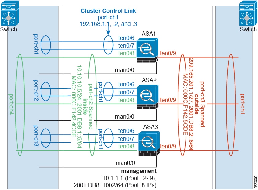
You may prefer physical separation of traffic between the inside and outside network.
As shown in the diagram above, there is one Spanned EtherChannel on the left side that connects to the inside switch, and the other on the right side to outside switch. You can also create VLAN subinterfaces on each EtherChannel if desired.
ASA1 Master Bootstrap Configuration
interface tengigabitethernet 0/6
interface tengigabitethernet 0/7
ASA2 Slave Bootstrap Configuration
interface tengigabitethernet 0/6
interface tengigabitethernet 0/7
ASA3 Slave Bootstrap Configuration
interface tengigabitethernet 0/6
interface tengigabitethernet 0/7
Master Interface Configuration
ip local pool mgmt 10.1.1.2-10.1.1.9
ipv6 local pool mgmtipv6 2001:DB8::1002/64 8
interface tengigabitethernet 0/8
interface tengigabitethernet 0/9
Spanned EtherChannel with Backup Links (Traditional 8 Active/8 Standby)
The maximum number of active ports in a traditional EtherChannel is limited to 8 from the switch side. If you have an 8-ASA cluster, and you allocate 2 ports per unit to the EtherChannel, for a total of 16 ports total, then 8 of them have to be in standby mode. The ASA uses LACP to negotiate which links should be active or standby. If you enable multi-switch EtherChannel using VSS or vPC, you can achieve inter-switch redundancy. On the ASA, all physical ports are ordered first by the slot number then by the port number. In the following figure, the lower ordered port is the “primary” port (for example, GigabitEthernet 0/0), and the other one is the “secondary” port (for example, GigabitEthernet 0/1). You must guarantee symmetry in the hardware connection: all primary links must terminate on one switch, and all secondary links must terminate on another switch if VSS/vPC is used. The following diagram shows what happens when the total number of links grows as more units join the cluster:
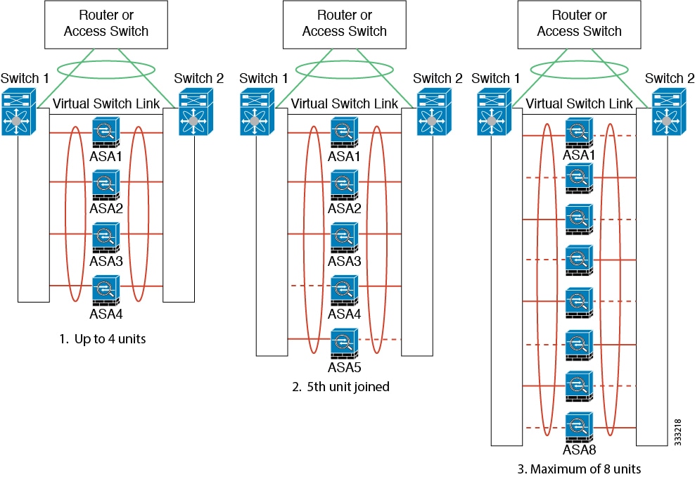
The principle is to first maximize the number of active ports in the channel, and secondly keep the number of active primary ports and the number of active secondary ports in balance. Note that when a 5th unit joins the cluster, traffic is not balanced evenly between all units.
Link or device failure is handled with the same principle. You may end up with a less-than-perfect load balancing situation. The following figure shows a 4-unit cluster with a single link failure on one of the units.
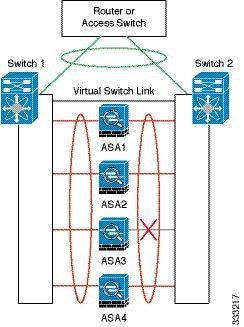
There could be multiple EtherChannels configured in the network. The following diagram shows an EtherChannel on the inside and one on the outside. An ASA is removed from the cluster if both primary and secondary links in one EtherChannel fail. This prevents the ASA from receiving traffic from the outside network when it has already lost connectivity to the inside network.
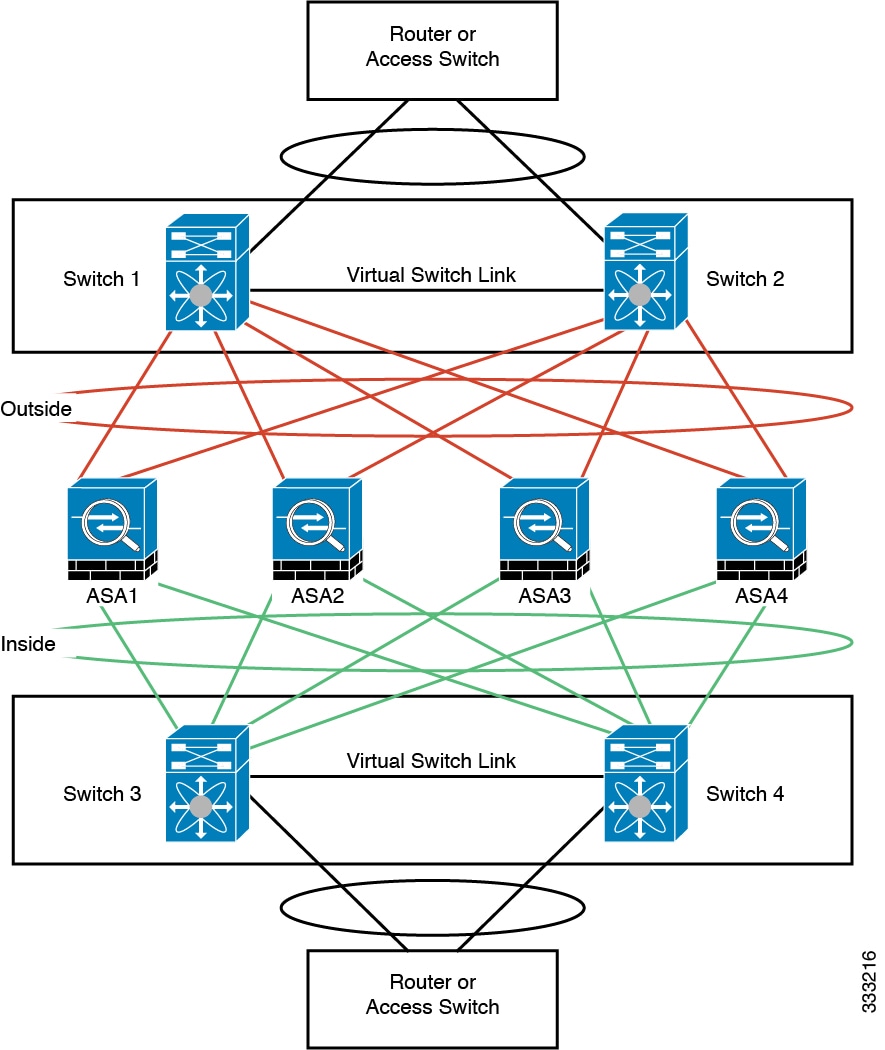
ASA1 Master Bootstrap Configuration
interface tengigabitethernet 0/6
interface tengigabitethernet 0/7
interface tengigabitethernet 0/8
interface tengigabitethernet 0/9
ASA2 Slave Bootstrap Configuration
interface tengigabitethernet 0/6
interface tengigabitethernet 0/7
interface tengigabitethernet 0/8
interface tengigabitethernet 0/9
ASA3 Slave Bootstrap Configuration
interface tengigabitethernet 0/6
interface tengigabitethernet 0/7
interface tengigabitethernet 0/8
interface tengigabitethernet 0/9
ASA4 Slave Bootstrap Configuration
interface tengigabitethernet 0/6
interface tengigabitethernet 0/7
interface tengigabitethernet 0/8
interface tengigabitethernet 0/9
Master Interface Configuration
ip local pool mgmt 10.1.1.2-10.1.1.9
interface tengigabitethernet 1/6
interface tengigabitethernet 1/7
interface tengigabitethernet 1/8
interface tengigabitethernet 1/9
Feature History for ASA Clustering
Table 9-3 lists each feature change and the platform release in which it was implemented.
 Feedback