- Preface
- Product Overview
- Installing Cisco Fabric Manager
- Fabric Manager Server
- Authentication in Fabric Manager
- Fabric Manager Client
- Device Manager
- Using Cisco Fabric Services
- Configuring Ethernet Interfaces
- Configuring Virtual Interfaces
- Configuring Fibre Channel Interfaces
- Configuring N-Port Virtualization
- Configuring Domain Parameters
- Configuring VSAN Trunking
- Configuring and Managing VSANs
- Configuring and Managing Zones
- Distributing Device Alias Services
- Configuring Fibre Channel Routing Services and Protocols
- Managing FLOGI, Name Server, FDMI, and RSCN Databases
- Configuring SPAN
- Discovering SCSI Targets
- Configuring SAN PortChannels
- Advanced Features and Concepts
- Configuring FC-SP and DHCHAP
- Configuring Port Security
- Configuring Fabric Binding
- Configuring Fabric Configuration Servers
- Configuring Port Tracking
- Network Monitoring
- Performance Manager
- Nexus 5000 Management Software FAQ
- Troubleshooting Your Fabric
- Index
Configuring and Managing Zones
Zoning enables you to set up access control between storage devices or user groups. If you have administrator privileges in your fabric, you can create zones to increase network security and to prevent data loss or corruption. Zoning is enforced by examining the source-destination ID field.
Advanced zoning capabilities specified in the FC-GS-4 and FC-SW-3 standards are supported. You can use either the existing basic zoning capabilities or the advanced, standards-compliant zoning capabilities.
This chapter includes the following sections:

Note ![]() Table 15-1 on page 15-4 lists the differences between zones and VSANs.
Table 15-1 on page 15-4 lists the differences between zones and VSANs.
Information About Zoning
Zoning is described in the following topics:
•![]() Active and Full Zone Set Configuration Guidelines
Active and Full Zone Set Configuration Guidelines
Zoning Features
Zoning includes the following features:
•![]() A zone consists of multiple zone members.
A zone consists of multiple zone members.
–![]() Members in a zone can access each other; members in different zones cannot access each other.
Members in a zone can access each other; members in different zones cannot access each other.
–![]() If zoning is not activated, all devices are members of the default zone.
If zoning is not activated, all devices are members of the default zone.
–![]() If zoning is activated, any device that is not in an active zone (a zone that is part of an active zone set) is a member of the default zone.
If zoning is activated, any device that is not in an active zone (a zone that is part of an active zone set) is a member of the default zone.
–![]() Zones can vary in size.
Zones can vary in size.
–![]() Devices can belong to more than one zone.
Devices can belong to more than one zone.
–![]() A physical fabric can have a maximum of 16,000 members. This includes all VSANs in the fabric.
A physical fabric can have a maximum of 16,000 members. This includes all VSANs in the fabric.
•![]() A zone set consists of one or more zones.
A zone set consists of one or more zones.
–![]() A zone set can be activated or deactivated as a single entity across all switches in the fabric.
A zone set can be activated or deactivated as a single entity across all switches in the fabric.
–![]() Only one zone set can be activated at any time.
Only one zone set can be activated at any time.
–![]() A zone can be a member of more than one zone set.
A zone can be a member of more than one zone set.
–![]() A zone switch can have a maximum of 500 zone sets.
A zone switch can have a maximum of 500 zone sets.
•![]() Zoning can be administered from any switch in the fabric.
Zoning can be administered from any switch in the fabric.
–![]() When you activate a zone (from any switch), all switches in the fabric receive the active zone set. Additionally, full zone sets are distributed to all switches in the fabric, if this feature is enabled in the source switch.
When you activate a zone (from any switch), all switches in the fabric receive the active zone set. Additionally, full zone sets are distributed to all switches in the fabric, if this feature is enabled in the source switch.
–![]() If a new switch is added to an existing fabric, zone sets are acquired by the new switch.
If a new switch is added to an existing fabric, zone sets are acquired by the new switch.
•![]() Zone changes can be configured nondisruptively.
Zone changes can be configured nondisruptively.
–![]() New zones and zone sets can be activated without interrupting traffic on unaffected ports or devices.
New zones and zone sets can be activated without interrupting traffic on unaffected ports or devices.
•![]() Zone membership can be specified using the following identifiers:
Zone membership can be specified using the following identifiers:
–![]() Port world wide name (pWWN)—Specifies the pWWN of an N port attached to the switch as a member of the zone.
Port world wide name (pWWN)—Specifies the pWWN of an N port attached to the switch as a member of the zone.
–![]() Fabric pWWN—Specifies the WWN of the fabric port (switch port's WWN). This membership is also referred to as port-based zoning.
Fabric pWWN—Specifies the WWN of the fabric port (switch port's WWN). This membership is also referred to as port-based zoning.
–![]() FC ID—Specifies the FC ID of an N port attached to the switch as a member of the zone.
FC ID—Specifies the FC ID of an N port attached to the switch as a member of the zone.
–![]() Interface and switch WWN (sWWN)—Specifies the interface of a switch identified by the sWWN. This membership is also referred to as interface-based zoning.
Interface and switch WWN (sWWN)—Specifies the interface of a switch identified by the sWWN. This membership is also referred to as interface-based zoning.
–![]() Interface and domain ID—Specifies the interface of a switch identified by the domain ID.
Interface and domain ID—Specifies the interface of a switch identified by the domain ID.
–![]() Domain ID and port number—Specifies the domain ID of a Cisco switch domain and additionally specifies a port belonging to a non-Cisco switch.
Domain ID and port number—Specifies the domain ID of a Cisco switch domain and additionally specifies a port belonging to a non-Cisco switch.
Note ![]() For N ports attached to the switch over a virtual Fibre Channel interface, you can specify zone membership using the pWWN of the N port, the FC ID of the N port, or the fabric pWWN of the virtual Fibre Channel interface.
For N ports attached to the switch over a virtual Fibre Channel interface, you can specify zone membership using the pWWN of the N port, the FC ID of the N port, or the fabric pWWN of the virtual Fibre Channel interface.
•![]() Default zone membership includes all ports or WWNs that do not have a specific membership association. Access between default zone members is controlled by the default zone policy.
Default zone membership includes all ports or WWNs that do not have a specific membership association. Access between default zone members is controlled by the default zone policy.
•![]() You can configure up to 8000 zones per VSAN and a maximum of 8000 zones for all VSANs on the switch.
You can configure up to 8000 zones per VSAN and a maximum of 8000 zones for all VSANs on the switch.
Note ![]() Interface-based zoning only works with Cisco SAN switches. Interface-based zoning does not work for VSANs configured in interop mode.
Interface-based zoning only works with Cisco SAN switches. Interface-based zoning does not work for VSANs configured in interop mode.
Zoning Example
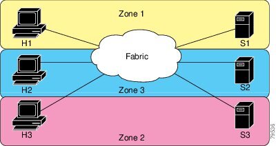
Figure 16-1 shows a zone set with two zones, zone 1 and zone 2, in a fabric. Zone 1 provides access from all three hosts (H1, H2, H3) to the data residing on storage systems S1 and S2. Zone 2 restricts the data on S3 to access only by H3. H3 resides in both zones.
Figure 16-1 Fabric with Two Zones

You can use other ways to partition this fabric into zones. Figure 16-2 shows another possibility. Assume that there is a need to isolate storage system S2 for the purpose of testing new software. To achieve this, zone 3 is configured, which contains only host H2 and storage S2. You can restrict access to only H2 and S2 in zone 3, and to H1 and S1 in zone 1.
Figure 16-2 Fabric with Three Zones
Zone Implementation
Cisco Nexus 5000 Series switches automatically support the following basic zone features (no additional configuration is required):
•![]() Zones are contained in a VSAN.
Zones are contained in a VSAN.
•![]() Hard zoning cannot be disabled.
Hard zoning cannot be disabled.
•![]() Name server queries are soft-zoned.
Name server queries are soft-zoned.
•![]() Only active zone sets are distributed.
Only active zone sets are distributed.
•![]() Unzoned devices cannot access each other.
Unzoned devices cannot access each other.
•![]() A zone or zone set with the same name can exist in each VSAN.
A zone or zone set with the same name can exist in each VSAN.
•![]() Each VSAN has a full database and an active database.
Each VSAN has a full database and an active database.
•![]() Active zone sets cannot be changed, without activating a full zone database.
Active zone sets cannot be changed, without activating a full zone database.
•![]() Active zone sets are preserved across switch reboots.
Active zone sets are preserved across switch reboots.
•![]() Changes to the full database must be explicitly saved.
Changes to the full database must be explicitly saved.
•![]() Zone reactivation (a zone set is active and you activate another zone set) does not disrupt existing traffic.
Zone reactivation (a zone set is active and you activate another zone set) does not disrupt existing traffic.
If required, you can additionally configure the following zone features:
•![]() Propagate full zone sets to all switches on a per VSAN basis.
Propagate full zone sets to all switches on a per VSAN basis.
•![]() Change the default policy for unzoned members.
Change the default policy for unzoned members.
•![]() Interoperate with other vendors by configuring a VSAN in the interop mode. You can also configure one VSAN in the interop mode and another VSAN in the basic mode in the same switch without disrupting each other.
Interoperate with other vendors by configuring a VSAN in the interop mode. You can also configure one VSAN in the interop mode and another VSAN in the basic mode in the same switch without disrupting each other.
•![]() Bring E ports out of isolation.
Bring E ports out of isolation.
Active and Full Zone Set Configuration Guidelines
Before configuring a zone set, consider the following guidelines:
•![]() Each VSAN can have multiple zone sets but only one zone set can be active at any given time.
Each VSAN can have multiple zone sets but only one zone set can be active at any given time.
•![]() When you create a zone set, that zone set becomes a part of the full zone set.
When you create a zone set, that zone set becomes a part of the full zone set.
•![]() When you activate a zone set, a copy of the zone set from the full zone set is used to enforce zoning, and is called the active zone set. An active zone set cannot be modified. A zone that is part of an active zone set is called an active zone.
When you activate a zone set, a copy of the zone set from the full zone set is used to enforce zoning, and is called the active zone set. An active zone set cannot be modified. A zone that is part of an active zone set is called an active zone.
•![]() The administrator can modify the full zone set even if a zone set with the same name is active. However, the modification will be enforced only upon reactivation.
The administrator can modify the full zone set even if a zone set with the same name is active. However, the modification will be enforced only upon reactivation.
•![]() When the activation is done, the active zone set is automatically stored in persistent configuration. This enables the switch to preserve the active zone set information across switch resets.
When the activation is done, the active zone set is automatically stored in persistent configuration. This enables the switch to preserve the active zone set information across switch resets.
•![]() All other switches in the fabric receive the active zone set so they can enforce zoning in their respective switches.
All other switches in the fabric receive the active zone set so they can enforce zoning in their respective switches.
•![]() Hard and soft zoning are implemented using the active zone set. Modifications take effect during zone set activation.
Hard and soft zoning are implemented using the active zone set. Modifications take effect during zone set activation.
•![]() An FC ID or Nx port that is not part of the active zone set belongs to the default zone and the default zone information is not distributed to other switches.
An FC ID or Nx port that is not part of the active zone set belongs to the default zone and the default zone information is not distributed to other switches.
Note ![]() If one zone set is active and you activate another zone set, the currently active zone set is automatically deactivated. You do not need to explicitly deactivate the currently active zone set before activating a new zone set.
If one zone set is active and you activate another zone set, the currently active zone set is automatically deactivated. You do not need to explicitly deactivate the currently active zone set before activating a new zone set.
Figure 16-3 shows a zone being added to an activated zone set.
Figure 16-3 Active and Full Zone Sets

Configuring Zones
This section describes how to configure zones and includes the following topics:
•![]() About the Zone Configuration Tool
About the Zone Configuration Tool
•![]() Configuring Zones Using the Zone Configuration Tool
Configuring Zones Using the Zone Configuration Tool
•![]() Configuring the Default Zone Policy
Configuring the Default Zone Policy
About the Zone Configuration Tool
The Zone Configuration tool allows you to zone across multiple switches and all zoning features are available through the Edit Local Full Zone Database dialog box (see Figure 16-4).
Figure 16-4 Edit Local Full Zone Database Dialog Box
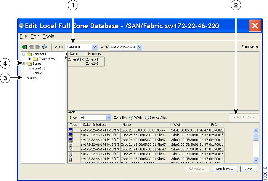
Note ![]() The Device Alias radio button is visible only if device alias is in enhanced mode. For more information, see the "Configuring Device Alias Modes" section on page 17-4.
The Device Alias radio button is visible only if device alias is in enhanced mode. For more information, see the "Configuring Device Alias Modes" section on page 17-4.

Tip ![]() Expand Switches from the Physical Attributes pane to retrieve the switch world-wide name (sWWN). If you do not provide a sWWN, the software automatically uses the local sWWN.
Expand Switches from the Physical Attributes pane to retrieve the switch world-wide name (sWWN). If you do not provide a sWWN, the software automatically uses the local sWWN.
Configuring Zones Using the Zone Configuration Tool
To create a zone and move it into a zone set using Fabric Manager, perform this task:
Step 1 ![]() Click the Zone icon in the toolbar (See Figure 16-5).
Click the Zone icon in the toolbar (See Figure 16-5).
Figure 16-5 Zone Icon

You see the Select VSAN dialog box.
Step 2 ![]() Choose the VSAN where you want to create a zone and click OK.
Choose the VSAN where you want to create a zone and click OK.
You see the Edit Local Full Zone Database dialog box as shown in Figure 16-6.
Figure 16-6 Edit Local Full Zone Database Dialog Box

If you want to view zone membership information, right-click in the All Zone Membership(s) column, and then choose Show Details for the current row or all rows from the pop-up menu.
Step 3 ![]() Click Zones in the left pane and click the Insert icon to create a zone.
Click Zones in the left pane and click the Insert icon to create a zone.
You see the Create Zone dialog box as shown in Figure 16-7.
Figure 16-7 Create Zone Dialog Box

Step 4 ![]() Enter a zone name.
Enter a zone name.
Step 5 ![]() Check one of the following check boxes:
Check one of the following check boxes:
a. ![]() Read Only—The zone permits read and denies write.
Read Only—The zone permits read and denies write.
b. ![]() Permit QoS traffic with Priority—You set the priority from the drop-down list.
Permit QoS traffic with Priority—You set the priority from the drop-down list.
c. ![]() Restrict Broadcast frames to Zone Members
Restrict Broadcast frames to Zone Members
Step 6 ![]() Click OK to create the zone.
Click OK to create the zone.
If you want to move this zone into an existing zone set, skip to Step 8.
Step 7 ![]() Click Zoneset in the left pane and click the Insert icon to create a zone set.
Click Zoneset in the left pane and click the Insert icon to create a zone set.
You see the Zoneset Name dialog box as shown in Figure 16-8.
Figure 16-8 Zoneset Name Dialog Box

Step 8 ![]() Enter a zone set name and click OK.
Enter a zone set name and click OK.
Note ![]() One of these symbols ($, -, ^, _) or all alphanumeric characters are supported. In interop mode 2 and 3, this symbol (_) or all alphanumeric characters are supported.
One of these symbols ($, -, ^, _) or all alphanumeric characters are supported. In interop mode 2 and 3, this symbol (_) or all alphanumeric characters are supported.
Step 9 ![]() Choose the zone set where you want to add a zone and click the Insert icon, or you can drag and drop Zone3 over Zoneset1.
Choose the zone set where you want to add a zone and click the Insert icon, or you can drag and drop Zone3 over Zoneset1.
You see the Select Zone dialog box as shown in Figure 16-9.
Figure 16-9 Select Zone Dialog Box

Step 10 ![]() Click Add to add the zone.
Click Add to add the zone.
Adding Zone Members
After you create a zone, you can add members to the zone. You can add members using multiple port identification types.
To add a member to a zone using Fabric Manager, perform this task:
Step 1 ![]() Choose Zone > Edit Local Full Zone Database.
Choose Zone > Edit Local Full Zone Database.
You see the Select VSAN dialog box.
Step 2 ![]() Choose a VSAN and click OK.
Choose a VSAN and click OK.
You see the Edit Local Full Zone Database dialog box (see Figure 16-10) for the selected VSAN.
Figure 16-10 Edit Local Full Zone Database Dialog Box

Step 3 ![]() Select the members you want to add from the Fabric pane and click Add to Zone or click the zone where you want to add members and click the Insert icon.
Select the members you want to add from the Fabric pane and click Add to Zone or click the zone where you want to add members and click the Insert icon.
You see the Add Member to Zone dialog box as shown in Figure 16-11.
Figure 16-11 Add Member to Zone Dialog Box

Note ![]() The Device Alias radio button is visible only if device alias is in enhanced mode. For more information, see the "Configuring Device Alias Modes" section on page 17-4.
The Device Alias radio button is visible only if device alias is in enhanced mode. For more information, see the "Configuring Device Alias Modes" section on page 17-4.
Step 4 ![]() Click the browse button and choose a port name or check the LUN check box and click the browse button to configure LUNs.
Click the browse button and choose a port name or check the LUN check box and click the browse button to configure LUNs.
Step 5 ![]() Click Add to add the member to the zone.
Click Add to add the member to the zone.
Note ![]() When configuring a zone member, you can specify that a single LUN has multiple IDs depending on the operating system. You can select from six different operating systems.
When configuring a zone member, you can specify that a single LUN has multiple IDs depending on the operating system. You can select from six different operating systems.
Configuring the Default Zone Policy
To permit or deny traffic in the default zone using Fabric Manager, perform this task:
Step 1 ![]() Choose Zone > Edit Local Full Zone Database.
Choose Zone > Edit Local Full Zone Database.
You see the Select VSAN dialog box.
Step 2 ![]() Choose a VSAN and click OK.
Choose a VSAN and click OK.
You see the Edit Local Full Zone Database dialog box for the selected VSAN.
Step 3 ![]() Choose Edit > Edit Default Zone Attributes to configure the default zone QoS priority attributes.
Choose Edit > Edit Default Zone Attributes to configure the default zone QoS priority attributes.
You see the Modify Default Zone Properties dialog box as shown in Figure 16-12.
Figure 16-12 Modify Default Zone Properties Dialog Box

Step 4 ![]() Set the Policy drop-down list to permit to permit traffic in the default zone, or set it to deny to block traffic in the default zone.
Set the Policy drop-down list to permit to permit traffic in the default zone, or set it to deny to block traffic in the default zone.
Step 5 ![]() Click OK to save these changes.
Click OK to save these changes.
Zone Sets
This section describes zone sets and includes the following topics:
•![]() Displaying Zone Membership Information
Displaying Zone Membership Information
•![]() Converting Zone Members to pWWN-Based Members
Converting Zone Members to pWWN-Based Members
About Zone Set Creation
In Figure 16-13, two separate sets are created, each with its own membership hierarchy and zone members.
Figure 16-13 Hierarchy of Zone Sets, Zones, and Zone Members
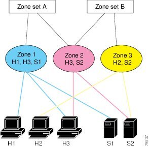
Zones provide a method for specifying access control, while zone sets are a grouping of zones to enforce access control in the fabric. Either zone set A or zone set B can be activated (but not together).
Tip ![]() Zone sets are configured with the names of the member zones and the VSAN (if the zone set is in a configured VSAN).
Zone sets are configured with the names of the member zones and the VSAN (if the zone set is in a configured VSAN).
Activating a Zone Set
Changes to a zone set do not take effect in a full zone set until you activate it.
To activate an existing zone set using Fabric Manager, perform this task:
Step 1 ![]() Choose Zone > Edit Local Full Zone Database.
Choose Zone > Edit Local Full Zone Database.
You see the Select VSAN dialog box.
Step 2 ![]() Choose a VSAN and click OK.
Choose a VSAN and click OK.
You see the Edit Local Full Zone Database dialog box for the selected VSAN.
Step 3 ![]() Click Activate to activate the zone set.
Click Activate to activate the zone set.
You see the preactivation check dialog box as shown in Figure 16-14.
Figure 16-14 Pre-Activation Check Dialog Box

Step 4 ![]() Click Yes to review the differences.
Click Yes to review the differences.
You see the Local vs. Active Differences dialog box as shown in Figure 16-15.
Figure 16-15 Local vs. Active Differences Dialog Box

Step 5 ![]() Click Close to close the dialog box.
Click Close to close the dialog box.
You see the Save Configuration dialog box as shown in Figure 16-16.
Figure 16-16 Save Configuration Dialog Box

Step 6 ![]() Check the Save Running to Startup Configuration check box to save all changes to the startup configuration.
Check the Save Running to Startup Configuration check box to save all changes to the startup configuration.
Step 7 ![]() Click Continue Activation to activate the zone set, or click Cancel to close the dialog box and discard any unsaved changes.
Click Continue Activation to activate the zone set, or click Cancel to close the dialog box and discard any unsaved changes.
You see the Zone Log dialog box, which shows if the zone set activation was successful (see Figure 16-17).
Figure 16-17 Zone Log Dialog Box

To deactivate an existing zone set, perform this task:
Step 1 ![]() Right-click the zone set you want to deactivate, and then choose Deactivate from the pop-up menu.
Right-click the zone set you want to deactivate, and then choose Deactivate from the pop-up menu.
Step 2 ![]() Click OK in the confirmation dialog box to deactivate the zone set.
Click OK in the confirmation dialog box to deactivate the zone set.
Displaying Zone Membership Information
To display zone membership information for members assigned to zones in Fabric Manager, perform this task:
Step 1 ![]() Choose Zone > Edit Local Full Zone Database.
Choose Zone > Edit Local Full Zone Database.
You see the Select VSAN dialog box.
Step 2 ![]() Choose a VSAN and click OK.
Choose a VSAN and click OK.
You see the Edit Local Full Zone Database dialog box for the selected VSAN.
Step 3 ![]() Click Zones in the left pane. The right pane lists the members for each zone.
Click Zones in the left pane. The right pane lists the members for each zone.
Note ![]() The default zone members are explicitly listed only when the default zone policy is configured as permit. When the default zone policy is configured as deny, the members of this zone are not shown. See the "Verifying Zone Information" section.
The default zone members are explicitly listed only when the default zone policy is configured as permit. When the default zone policy is configured as deny, the members of this zone are not shown. See the "Verifying Zone Information" section.
About the Default Zone
Each member of a fabric (in effect a device attached to an Nx port) can belong to any zone. If a member is not part of any active zone, it is considered to be part of the default zone. Therefore, if no zone set is active in the fabric, all devices are considered to be in the default zone. Even though a member can belong to multiple zones, a member that is part of the default zone cannot be part of any other zone. The switch determines whether a port is a member of the default zone when the attached port comes up.
Note ![]() Unlike configured zones, default zone information is not distributed to the other switches in the fabric.
Unlike configured zones, default zone information is not distributed to the other switches in the fabric.
Traffic can either be permitted or denied among members of the default zone. This information is not distributed to all switches; it must be configured in each switch.
Note ![]() When the switch is initialized for the first time, no zones are configured and all members are considered to be part of the default zone. Members are not permitted to communicate with each other.
When the switch is initialized for the first time, no zones are configured and all members are considered to be part of the default zone. Members are not permitted to communicate with each other.
Configure the default zone policy on each switch in the fabric. If you change the default zone policy on one switch in a fabric, be sure to change it on all the other switches in the fabric.
Note ![]() The default settings for default zone configurations can be changed.
The default settings for default zone configurations can be changed.
The default zone members are explicitly listed when the default policy is configured as permit or when a zone set is active. When the default policy is configured as deny, the members of this zone are not explicitly enumerated when you view the active zone set.
You can change the default zone policy for any VSAN by choosing VSANxx > Default Zone from the Logical Domains pane and clicking the Policies tab. It is recommended that you establish connectivity among devices by assigning them to a nondefault zone.
Configuring the Default Zone
To permit or deny traffic to members in the default zone using Fabric Manager, perform this task:
Step 1 ![]() Expand a VSAN, and then choose Default Zone in the Fabric Manager Logical Domains pane.
Expand a VSAN, and then choose Default Zone in the Fabric Manager Logical Domains pane.
Step 2 ![]() Click the Policies tab in the Information pane.
Click the Policies tab in the Information pane.
You see the zone policies information in the Information pane (see Figure 16-18).
Figure 16-18 Default Zone Policies

The active zone set is shown in italic type. After you make changes to the active zone set and before you activate the changes, the zone set is shown in boldface italic type.
Step 3 ![]() In the Default Zone Behavior field, choose either permit or deny from the drop-down list.
In the Default Zone Behavior field, choose either permit or deny from the drop-down list.
About FC Alias Creation
You can assign an alias name and configure an alias member using the following values:
•![]() pWWN—The WWN of the N port is in hex format (for example, 10:00:00:23:45:67:89:ab).
pWWN—The WWN of the N port is in hex format (for example, 10:00:00:23:45:67:89:ab).
•![]() fWWN—The WWN of the fabric port name is in hex format (for example, 10:00:00:23:45:67:89:ab).
fWWN—The WWN of the fabric port name is in hex format (for example, 10:00:00:23:45:67:89:ab).
•![]() FC ID—The N port ID is in 0xhhhhhh format (for example, 0xce00d1).
FC ID—The N port ID is in 0xhhhhhh format (for example, 0xce00d1).
•![]() Domain ID—The domain ID is an integer from 1 to 239. A mandatory port number of a non-Cisco switch is required to complete this membership configuration.
Domain ID—The domain ID is an integer from 1 to 239. A mandatory port number of a non-Cisco switch is required to complete this membership configuration.
•![]() Interface—Interface-based zoning is similar to port-based zoning because the switch interface is used to configure the zone. You can specify a switch interface as a zone member for both local and remote switches. To specify a remote switch, enter the remote switch WWN (sWWN) or the domain ID in the particular VSAN.
Interface—Interface-based zoning is similar to port-based zoning because the switch interface is used to configure the zone. You can specify a switch interface as a zone member for both local and remote switches. To specify a remote switch, enter the remote switch WWN (sWWN) or the domain ID in the particular VSAN.
Tip ![]() The switch supports a maximum of 2048 aliases per VSAN.
The switch supports a maximum of 2048 aliases per VSAN.
Creating FC Aliases
To create an FC alias using Fabric Manager, perform this task:
Step 1 ![]() Choose Zone > Edit Local Full Zone Database.
Choose Zone > Edit Local Full Zone Database.
You see the Select VSAN dialog box.
Step 2 ![]() Choose a VSAN and click OK.
Choose a VSAN and click OK.
You see the Edit Local Full Zone Database dialog box for the selected VSAN.
Step 3 ![]() Click FC-Aliases in the lower left pane (see Figure 16-19). The right pane lists the existing aliases.
Click FC-Aliases in the lower left pane (see Figure 16-19). The right pane lists the existing aliases.
Figure 16-19 Creating an FC Alias

Step 4 ![]() Click the Insert icon to create an alias.
Click the Insert icon to create an alias.
You see the Create Alias dialog box as shown in Figure 16-20.
Figure 16-20 Create Alias Dialog Box

Step 5 ![]() Set the Alias Name and the pWWN.
Set the Alias Name and the pWWN.
Step 6 ![]() Click OK to create the alias.
Click OK to create the alias.
Adding Members to Aliases
To add a member to an alias using Fabric Manager, perform this task:
Step 1 ![]() Choose Zone > Edit Local Full Zone Database.
Choose Zone > Edit Local Full Zone Database.
You see the Select VSAN dialog box.
Step 2 ![]() Choose a VSAN and click OK.
Choose a VSAN and click OK.
You see the Edit Local Full Zone Database dialog box for the selected VSAN as shown in Figure 16-21.
Figure 16-21 Edit Local Full Zone Database Dialog Box

Step 3 ![]() Click the alias (in the FC-Aliases folder) where you want to add members.
Click the alias (in the FC-Aliases folder) where you want to add members.
Step 4 ![]() Select the member(s) you want to add from the Fabric pane (see Figure 16-21) and click Add to Alias.
Select the member(s) you want to add from the Fabric pane (see Figure 16-21) and click Add to Alias.
Fabric Manager provides an alternative method for adding members to the alias. Instead of step 4, perform steps 5 through 7.
Step 5 ![]() Click the alias where you want to add members and click the Insert icon.
Click the alias where you want to add members and click the Insert icon.
You see the Add Member to Alias dialog box as shown in Figure 16-22.
Figure 16-22 Add Member to Alias Dialog Box

Note ![]() The Device Alias radio button is visible only if device alias is in enhanced mode. For more information, see Configuring Device Alias Modes, page 17-4.
The Device Alias radio button is visible only if device alias is in enhanced mode. For more information, see Configuring Device Alias Modes, page 17-4.
Step 6 ![]() Click the browse button and choose a port name or check the LUN check box and click the browse button to configure LUNS.
Click the browse button and choose a port name or check the LUN check box and click the browse button to configure LUNS.
Step 7 ![]() Click Add to add the member to the alias.
Click Add to add the member to the alias.
Converting Zone Members to pWWN-Based Members
You can convert zone and alias members from switch port or FC ID based membership to pWWN-based membership. You can use this feature to convert to pWWN so that your zone configuration does not change if a switch is changed in your fabric.
To convert switch port and FC ID members to pWWN members using Fabric Manager, perform this task:
Step 1 ![]() Choose Zone > Edit Local Full Zone Database.
Choose Zone > Edit Local Full Zone Database.
You see the Select VSAN dialog box.
Step 2 ![]() Choose a VSAN and click OK.
Choose a VSAN and click OK.
You see the Edit Local Full Zone Database dialog box for the selected VSAN.
Step 3 ![]() Click the zone you want to convert.
Click the zone you want to convert.
Step 4 ![]() Choose Tools > Convert Switch Port/FCID members to By pWWN.
Choose Tools > Convert Switch Port/FCID members to By pWWN.
You see the conversion dialog box, listing all members that will be converted.
Step 5 ![]() Verify the changes and click Continue Conversion.
Verify the changes and click Continue Conversion.
Step 6 ![]() Click Yes in the confirmation dialog box to convert that member to pWWN-based membership.
Click Yes in the confirmation dialog box to convert that member to pWWN-based membership.
Tip ![]() You do not have to copy the running configuration to the startup configuration to store the active zone set. However, you need to copy the running configuration to the startup configuration to explicitly store full zone sets.
You do not have to copy the running configuration to the startup configuration to store the active zone set. However, you need to copy the running configuration to the startup configuration to explicitly store full zone sets.
Note ![]() The pWWN of the virtual target does not appear in the zoning end devices database in Fabric Manager. If you want to zone the virtual device with a pWWN, you must enter it in the Add Member to Zone dialog box when creating a zone. However, if the device alias is in enhanced mode, the virtual device names appear in the device alias database in the Fabric Manager zoning window. In this case, users can choose to select either the device alias name or enter the pWWN in the Add Member to Zone dialog box. For more information, see the "Adding Zone Members" section.
The pWWN of the virtual target does not appear in the zoning end devices database in Fabric Manager. If you want to zone the virtual device with a pWWN, you must enter it in the Add Member to Zone dialog box when creating a zone. However, if the device alias is in enhanced mode, the virtual device names appear in the device alias database in the Fabric Manager zoning window. In this case, users can choose to select either the device alias name or enter the pWWN in the Add Member to Zone dialog box. For more information, see the "Adding Zone Members" section.
Note ![]() Be sure you understand how device alias modes work before enabling them. See Chapter 17, "Distributing Device Alias Services" for details and requirements about device alias modes.
Be sure you understand how device alias modes work before enabling them. See Chapter 17, "Distributing Device Alias Services" for details and requirements about device alias modes.
Zone Enforcement
Zoning can be enforced in two ways: soft and hard. Each end device (N port) discovers other devices in the fabric by querying the name server. When a device logs in to the name server, the name server returns the list of other devices that can be accessed by the querying device. If an N port does not know about the FC IDs of other devices outside its zone, it cannot access those devices.
In soft zoning, zoning restrictions are applied only during interaction between the name server and the end device. If an end device somehow knows the FC ID of a device outside its zone, it can access that device.
Hard zoning is enforced by the hardware on each frame sent by an N port. As frames enter the switch, source-destination IDs are compared with permitted combinations to allow the frame at wire speed. Hard zoning is applied to all forms of zoning.
Note ![]() Hard zoning enforces zoning restrictions on every frame, and prevents unauthorized access.
Hard zoning enforces zoning restrictions on every frame, and prevents unauthorized access.
Cisco Nexus 5000 Series switches support both hard and soft zoning.
Zone Set Distribution
You can distribute full zone sets using one of two methods: one-time distribution or full zone set distribution. Table 16-1 lists the differences between the methods.
This section describes zone set distribution and includes the following topics:
•![]() Enabling Full Zone Set Distribution
Enabling Full Zone Set Distribution
•![]() Enabling a One-Time Distribution
Enabling a One-Time Distribution
•![]() About Recovering from Link Isolation
About Recovering from Link Isolation
•![]() Importing and Exporting Zone Sets
Importing and Exporting Zone Sets
Enabling Full Zone Set Distribution
All switches in the Cisco Nexus 5000 Series distribute active zone sets when new E port links come up or when a new zone set is activated in a VSAN. The zone set distribution takes effect while sending merge requests to the adjacent switch or while activating a zone set.
To enable full zone set and active zone set distribution to all switches on a per VSAN basis using Fabric Manager, perform this task:
Step 1 ![]() Expand a VSAN and choose a zone set in the Logical Domains pane.
Expand a VSAN and choose a zone set in the Logical Domains pane.
You see the zone set configuration in the Information pane. The Active Zones tab is the default.
Step 2 ![]() Click the Policies tab.
Click the Policies tab.
You see the configured policies for the zone as shown in Figure 16-23.
Figure 16-23 Configured Policies for the Zone

Step 3 ![]() In the Propagation column, choose Full Zoneset from the drop-down list.
In the Propagation column, choose Full Zoneset from the drop-down list.
Step 4 ![]() Click Apply Changes to propagate the full zone set.
Click Apply Changes to propagate the full zone set.
Enabling a One-Time Distribution
You can perform a one-time distribution of inactive, unmodified zone sets throughout the fabric.
To propagate a one-time distribution of the full zone set using Fabric Manager, perform this task:
Step 1 ![]() Choose Zone > Edit Local Full Zone Database.
Choose Zone > Edit Local Full Zone Database.
You see the Edit Local Full Zone Database dialog box.
Step 2 ![]() Click the appropriate zone from the list in the left pane.
Click the appropriate zone from the list in the left pane.
Step 3 ![]() Click Distribute to distribute the full zone set across the fabric.
Click Distribute to distribute the full zone set across the fabric.
This procedure only distributes the full zone set information, it does not save the information to the startup configuration. To save the full zone set, you must explicitly save the running configuration to the startup configuration.
Note ![]() The one-time distribution of the full zone set is supported in interop 2 and interop 3 modes, and not in interop 1 mode.
The one-time distribution of the full zone set is supported in interop 2 and interop 3 modes, and not in interop 1 mode.
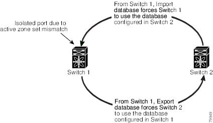
About Recovering from Link Isolation
When two switches in a fabric are merged using a TE or E port, these TE and E ports may become isolated when the active zone set databases are different between the two switches or fabrics. When a TE port or an E port become isolated, you can recover that port from its isolated state using one of three options:
•![]() Import the neighboring switch's active zone set database and replace the current active zone set (see Figure 16-24).
Import the neighboring switch's active zone set database and replace the current active zone set (see Figure 16-24).
•![]() Export the current database to the neighboring switch.
Export the current database to the neighboring switch.
•![]() Manually resolve the conflict by editing the full zone set, activating the corrected zone set, and then bringing up the link.
Manually resolve the conflict by editing the full zone set, activating the corrected zone set, and then bringing up the link.
Figure 16-24 Importing and Exporting the Database
Importing and Exporting Zone Sets
To import or export the zone set information from or to an adjacent switch using Fabric Manager, perform this task:
Step 1 ![]() Choose Zone > Edit Local Full Zone Database.
Choose Zone > Edit Local Full Zone Database.
You see the Edit Local Full Zone Database dialog box.
Step 2 ![]() Choose Tools > Zone Merge Fail Recovery.
Choose Tools > Zone Merge Fail Recovery.
You see the Zone Merge Failure Recovery dialog box as shown in Figure 16-25.
Figure 16-25 Zone Merge Failure Recovery Dialog Box

Step 3 ![]() Click the Import Active Zoneset or the Export Active Zoneset radio button.
Click the Import Active Zoneset or the Export Active Zoneset radio button.
Step 4 ![]() Choose the switch from which to import or export the zone set information from the drop-down list.
Choose the switch from which to import or export the zone set information from the drop-down list.
Step 5 ![]() Choose the VSAN from which to import or export the zone set information from the drop-down list.
Choose the VSAN from which to import or export the zone set information from the drop-down list.
Step 6 ![]() Choose the interface to use for the import process.
Choose the interface to use for the import process.
Step 7 ![]() Click OK to import or export the active zone set.
Click OK to import or export the active zone set.
Note ![]() Enter the import and export from a single switch. Importing from one switch and exporting from another switch can lead to isolation again.
Enter the import and export from a single switch. Importing from one switch and exporting from another switch can lead to isolation again.
Zone Set Duplication
You can make a copy and then edit it without altering the existing active zone set. You can copy an active zone set from the bootflash: directory, volatile: directory, or slot0 to one of the following areas:
•![]() To the full zone set
To the full zone set
•![]() To a remote location (using FTP, SCP, SFTP, or TFTP)
To a remote location (using FTP, SCP, SFTP, or TFTP)
The active zone set is not part of the full zone set. You cannot make changes to an existing zone set and activate it if the full zone set is lost or is not propagated.

This section includes the following topics:
•![]() About Backing Up and Restoring Zones
About Backing Up and Restoring Zones
•![]() Backing Up and Restoring Zones
Backing Up and Restoring Zones
•![]() Renaming Zones, Zone Sets, and Aliases
Renaming Zones, Zone Sets, and Aliases
•![]() Cloning Zones, Zone Sets, FC Aliases, and Zone Attribute Groups
Cloning Zones, Zone Sets, FC Aliases, and Zone Attribute Groups
•![]() Clearing the Zone Server Database
Clearing the Zone Server Database
Copying Zone Sets
On Cisco Nexus 5000 Series switches, you cannot edit an active zone set. However, you can copy an active zone set to create a new zone set that you can edit.
To make a copy of a zone set using Fabric Manager, perform this task:
Step 1 ![]() Choose Zone > Copy Full Zone Database.
Choose Zone > Copy Full Zone Database.
You see the Copy Full Zone Database dialog box as shown in Figure 16-26.
Figure 16-26 Copy Full Zone Database Dialog Box

Step 2 ![]() Click the Active or the Full radio button, depending on which type of database you want to copy.
Click the Active or the Full radio button, depending on which type of database you want to copy.
Step 3 ![]() Choose the source VSAN from the drop-down list.
Choose the source VSAN from the drop-down list.
Step 4 ![]() If you selected Copy Full, choose the source switch and the destination VSAN from those drop-down lists.
If you selected Copy Full, choose the source switch and the destination VSAN from those drop-down lists.
Step 5 ![]() Choose the destination switch from the drop-down list.
Choose the destination switch from the drop-down list.
Step 6 ![]() Click Copy to copy the database.
Click Copy to copy the database.
About Backing Up and Restoring Zones
You can back up the zone configuration to a workstation using TFTP. This zone backup file can then be used to restore the zone configuration on a switch. Restoring the zone configuration overwrites any existing zone configuration on a switch.
Backing Up and Restoring Zones
To back up or restore the full zone configuration using Fabric Manager, perform this task:
Step 1 ![]() Choose Zone > Edit Local Full Zone Database.
Choose Zone > Edit Local Full Zone Database.
You see the Select VSAN dialog box.
Step 2 ![]() Choose a VSAN and click OK.
Choose a VSAN and click OK.
You see the Edit Local Full Zone Database dialog box for the selected VSAN.
Step 3 ![]() Choose File > Backup to back up the existing zone configuration to a workstation using TFTP, or choose File > Restore to restore a saved zone configuration.
Choose File > Backup to back up the existing zone configuration to a workstation using TFTP, or choose File > Restore to restore a saved zone configuration.
You see the Restore Zone Configuration dialog box as shown in Figure 16-27.
Figure 16-27 Restore Zone Configuration Dialog Box

You can edit this configuration before restoring it to the switch.
Step 4 ![]() Click Continue Restore, or click Close to close the dialog box without restoring.
Click Continue Restore, or click Close to close the dialog box without restoring.
Renaming Zones, Zone Sets, and Aliases
To rename a zone, zone set, or alias using Fabric Manager, perform this task:
Step 1 ![]() Choose Zone > Edit Local Full Zone Database.
Choose Zone > Edit Local Full Zone Database.
You see the Select VSAN dialog box.
Step 2 ![]() Choose a VSAN and click OK.
Choose a VSAN and click OK.
You see the Edit Local Full Zone Database dialog box for the selected VSAN as shown in Figure 16-28.
Figure 16-28 Edit Local Full Zone Database Dialog Box

Step 3 ![]() Click a zone or zone set in the left pane.
Click a zone or zone set in the left pane.
Step 4 ![]() Choose Edit > Rename.
Choose Edit > Rename.
An edit box appears around the zone or zone set name.
Step 5 ![]() Enter a new name.
Enter a new name.
Step 6 ![]() Click Activate or Distribute.
Click Activate or Distribute.
Cloning Zones, Zone Sets, FC Aliases, and Zone Attribute Groups
To clone a zone, zone set, fcalias, or zone-attribute-group, perform this task:
Step 1 ![]() Choose Zone > Edit Local Full Zone Database.
Choose Zone > Edit Local Full Zone Database.
You see the Select VSAN dialog box.
Step 2 ![]() Choose a VSAN and click OK.
Choose a VSAN and click OK.
You see the Edit Local Full Zone Database dialog box for the selected VSAN.
Step 3 ![]() Choose Edit > Clone.
Choose Edit > Clone.
You see the Clone Zoneset dialog box as shown in Figure 16-29. The default name is the word Clone followed by the original name.
Figure 16-29 Clone Zoneset Dialog Box

Step 4 ![]() Change the name for the cloned entry.
Change the name for the cloned entry.
Step 5 ![]() Click OK to save the new clone.
Click OK to save the new clone.
The cloned database now appears along with the original database.
Migrating a Non-MDS Database
To use the Zone Migration Wizard to migrate a non-MDS database using Fabric Manager, perform this task:
Step 1 ![]() Choose Zone > Migrate Non-MDS Database.
Choose Zone > Migrate Non-MDS Database.
You see the Zone Migration Wizard.
Step 2 ![]() Follow the prompts in the wizard to migrate the database.
Follow the prompts in the wizard to migrate the database.
Clearing the Zone Server Database
You can clear all configured information in the zone server database for the specified VSAN.
To clear the zone server database, see the Cisco Cisco Nexus 5000 Series CLI Configuration Guide.
Note ![]() Clearing a zone set only erases the full zone database, not the active zone database.
Clearing a zone set only erases the full zone database, not the active zone database.
Note ![]() After clearing the zone server database, you must explicitly copy the running configuration to the startup configuration to save the configuration.
After clearing the zone server database, you must explicitly copy the running configuration to the startup configuration to save the configuration.
Verifying Zone Information
To view zone information and statistics using Fabric Manager, perform this task:
Step 1 ![]() Expand a VSAN and click a zone set in the Logical Domains pane.
Expand a VSAN and click a zone set in the Logical Domains pane.
You see the zone configuration in the Information pane.
Step 2 ![]() Click the Read Only Violations, Statistics tab or the LUN Zoning Statistics tab to view statistics for the selected zone.
Click the Read Only Violations, Statistics tab or the LUN Zoning Statistics tab to view statistics for the selected zone.
Enhanced Zoning
The zoning feature complies with the FC-GS-4 and FC-SW-3 standards. Both standards support the basic zoning functionalities explained in the previous section and the enhanced zoning functionalities described in this section.
This section includes the following topics:
•![]() Changing from Basic Zoning to Enhanced Zoning
Changing from Basic Zoning to Enhanced Zoning
•![]() Changing from Enhanced Zoning to Basic Zoning
Changing from Enhanced Zoning to Basic Zoning
•![]() Configuring Zone Merge Control Policies
Configuring Zone Merge Control Policies
About Enhanced Zoning
Table 16-2 lists the advantages of the enhanced zoning feature in all switches in the Cisco Nexus 5000 Series.
Changing from Basic Zoning to Enhanced Zoning
To change to the enhanced zoning mode from the basic mode, perform this task:
Step 1 ![]() Verify that all switches in the fabric are capable of working in the enhanced mode.
Verify that all switches in the fabric are capable of working in the enhanced mode.
If one or more switches are not capable of working in enhanced mode, then your request to move to enhanced mode is rejected.
Step 2 ![]() Set the operation mode to enhanced zoning mode.
Set the operation mode to enhanced zoning mode.
You will automatically start a session, acquire a fabric wide lock, distribute the active and full zoning database using the enhanced zoning data structures, distribute zoning policies and then release the lock. All switches in the fabric then move to the enhanced zoning mode.
Tip ![]() After moving from basic zoning to enhanced zoning, we recommend that you save the running configuration.
After moving from basic zoning to enhanced zoning, we recommend that you save the running configuration.
Changing from Enhanced Zoning to Basic Zoning
Cisco SAN switches allow you to change from enhanced zoning to basic zoning to enable you to downgrade and upgrade to other Cisco NX-OS releases.
To change to the basic zoning mode from the enhanced mode, perform this task:
Step 1 ![]() Verify that the active and full zone set do not contain any configuration that is specific to the enhanced zoning mode.
Verify that the active and full zone set do not contain any configuration that is specific to the enhanced zoning mode.
If such configurations exist, delete them before proceeding with this procedure. If you do not delete the existing configuration, the switch software automatically removes them.
Step 2 ![]() Set the operation mode to basic zoning mode.
Set the operation mode to basic zoning mode.
You will automatically start a session, acquire a fabric-wide lock, distribute the zoning information using the basic zoning data structure, apply the configuration changes and release the lock from all switches in the fabric. All switches in the fabric then move to basic zoning mode.
Enabling Enhanced Zoning
By default, the enhanced zoning feature is disabled in all switches in the Cisco Nexus 5000 Series.
To enable enhanced zoning in a VSAN using Fabric Manager, perform this task:
Step 1 ![]() In the Logical Domains pane, expand a VSAN, and then choose a zone set.
In the Logical Domains pane, expand a VSAN, and then choose a zone set.
You see the zone set configuration in the Information pane.
Step 2 ![]() Click the Enhanced tab.
Click the Enhanced tab.
You see the current enhanced zoning configuration.
Step 3 ![]() In the Action drop-down list, choose enhanced to enable enhanced zoning in this VSAN.
In the Action drop-down list, choose enhanced to enable enhanced zoning in this VSAN.
Step 4 ![]() Click Apply Changes to save these changes.
Click Apply Changes to save these changes.
Merging the Database
The merge method depends on the fabric-wide merge control setting:
•![]() Restrict—If the two databases are not identical, the ISLs between the switches are isolated.
Restrict—If the two databases are not identical, the ISLs between the switches are isolated.
•![]() Allow—The two databases are merged using the merge rules specified in Table 16-3.
Allow—The two databases are merged using the merge rules specified in Table 16-3.
|
|
|
|
|
|---|---|---|---|
The databases contain zone sets with the same name1 but different zones, aliases, and attributes groups. |
Successful. |
The union of the local and adjacent databases. |
|
The databases contains a zone, zone alias, or zone attribute group object with same name1 but different members. |
Failed. |
ISLs are isolated. |
|
Empty. |
Contains data. |
Successful. |
The adjacent database information populates the local database. |
Contains data. |
Empty. |
Successful. |
The local database information populates the adjacent database. |
1 In the enhanced zoning mode, the active zone set does not have a name in interop mode 1. The zone set names are only present for full zone sets. |
The merge process operates as follows:
1. ![]() The software compares the protocol versions. If the protocol versions differ, then the ISL is isolated.
The software compares the protocol versions. If the protocol versions differ, then the ISL is isolated.
2. ![]() If the protocol versions are the same, then the zone policies are compared. If the zone policies differ, then the ISL is isolated.
If the protocol versions are the same, then the zone policies are compared. If the zone policies differ, then the ISL is isolated.
3. ![]() If the zone merge options are the same, then the comparison is implemented based on the merge control setting.
If the zone merge options are the same, then the comparison is implemented based on the merge control setting.
a. ![]() If the setting is restrict, the active zone set and the full zone set should be identical. Otherwise, the link is isolated.
If the setting is restrict, the active zone set and the full zone set should be identical. Otherwise, the link is isolated.
b. ![]() If the setting is allow, then the merge rules are used to perform the merge.
If the setting is allow, then the merge rules are used to perform the merge.
Analyzing a Zone Merge
To perform a zone merge analysis using Fabric Manager, perform this task:
Step 1 ![]() Choose Zone > Merge Analysis.
Choose Zone > Merge Analysis.
You see the Zone Merge Analysis dialog box as shown in Figure 16-30.
Figure 16-30 Zone Merge Analysis Dialog Box

Step 2 ![]() Choose the first switch to be analyzed from the Check Switch 1 drop-down list.
Choose the first switch to be analyzed from the Check Switch 1 drop-down list.
Step 3 ![]() Choose the second switch to be analyzed from the And Switch 2 drop-down list.
Choose the second switch to be analyzed from the And Switch 2 drop-down list.
Step 4 ![]() Enter the VSAN ID where the zone set merge failure occurred in the For Active Zoneset Merge Problems in VSAN Id field.
Enter the VSAN ID where the zone set merge failure occurred in the For Active Zoneset Merge Problems in VSAN Id field.
Step 5 ![]() Click Analyze to analyze the zone merge.
Click Analyze to analyze the zone merge.
Step 6 ![]() Click Clear to clear the analysis data in the Zone Merge Analysis dialog box.
Click Clear to clear the analysis data in the Zone Merge Analysis dialog box.
Configuring Zone Merge Control Policies
To configure merge control policies, see the Cisco Cisco Nexus 5000 Series CLI Configuration Guide.
Compacting the Zone Database
You can delete excess zones and compact the zone database for the VSAN.
Note ![]() A merge failure occurs when a switch supports more than 2000 zones per VSAN but its neighbor does not. Also, zone set activation can fail if the switch has more than 2000 zones per VSAN and not all switches in the fabric support more than 2000 zones per VSAN.
A merge failure occurs when a switch supports more than 2000 zones per VSAN but its neighbor does not. Also, zone set activation can fail if the switch has more than 2000 zones per VSAN and not all switches in the fabric support more than 2000 zones per VSAN.
To compact the zone database for downgrading, see the Cisco Cisco Nexus 5000 Series CLI Configuration Guide.
Default Settings
Table 16-4 lists the default settings for basic zone parameters.
|
|
|
|---|---|
Default zone policy |
Denied to all members. |
Full zone set distribute |
The full zone set(s) is not distributed. |
Enhanced zoning |
Disabled. |
 Feedback