-
Dial Technologies Configuration Guide, Cisco IOS Release 15.2S
- Part 1: Dial Interfaces, Controllers, and Lines
-
Part 2 - Modem Configuration and Management
-
Overview of Modem Interfaces
-
Configuring and Managing Integrated Modems
-
1- and 2-Port V.90 Modem WICs for Cisco 2600 and Cisco 3600 Series Multiservice Platforms
-
Call Tracker show Commands Extensions
-
Cisco NM-8AM-V2 and NM-16AM-V2 Analog Modem Network Modules with V.92
-
MICA and NextPort Modem Tech-Support Command Additions
-
PIAFS Wireless Data Protocol Version 2.1 for Cisco MICA Modems
-
V.92 and V.44 Support for Digital Modems
-
V.92 Modem on Hold for Cisco AS5300 and Cisco AS5800 Universal Access Servers
-
V.92 Modem on Hold for Cisco AS5350, Cisco AS5400, and Cisco AS5850 Universal Gateways and Cisco AS5800 Universal Access Servers
-
V.92 Quick Connect for Cisco AS5300 and Cisco AS5800 Universal Access Servers
-
V.92 Quick Connect for Cisco AS5350, Cisco AS5400, and Cisco AS5850 Universal Gateways and Cisco AS5800 Universal Access Servers
-
V.92 Reporting Using RADIUS Attribute v.92-info
-
Configuring and Managing Cisco Access Servers and Dial Shelves
-
Configuring and Managing External Modems
-
Modem Signal and Line States
-
Creating and Using Modem Chat Scripts
-
Cisco Modem User Interface
-
Modem Script and System Script Support in Large-Scale Dial-Out
-
- Part 3 - ISDN Configuration
- Part 4 - Signaling Configuration
-
Part 5 - Dial-on-Demand Routing Configuration
-
Preparing to Configure DDR
-
Configuring Legacy DDR Spokes
-
Configuring Legacy DDR Hubs
-
Configuring Peer-to-Peer DDR with Dialer Profiles
-
Dialer Map VRF-Aware for an MPLS VPN
-
Dialer Persistent
-
PPPoE Client DDR Idle-Timer
-
Redial Enhancements
-
Rotating Through Dial Strings
-
Configuring Dialer CEF
-
CEF Support for Dialer Profiles on Cisco 7500 Routers
-
Configuring Snapshot Routing
-
- Part 6: Dial-Backup Configuration
- Part 7: Dial-Related Addressing Services
- Part 8: Virtual Templates and Profiles
-
Part 9: PPP Configuration
-
Configuring Asynchronous SLIP and PPP
-
Optimized PPP Negotiation
-
Customer Profile Idle Timer Enhancements for Interesting Traffic
-
Multiclass Multilink PPP
-
Configuring Media-Independent PPP and Multilink PPP
-
PPP/MLP MRRU Negotiation Configuration
-
Troubleshooting Enhancements for Multilink PPP over ATM Link Fragmentation and Interleaving
-
Multichassis Multilink PPP
-
- Part 10: Callback and Bandwidth Allocation Configuration
- Part 11: Dial Access Specialized Features
- Appendix
 Feedback
Table Of Contents
Configuring Peer-to-Peer DDR with Dialer Profiles
How to Configure Dialer Profiles
Configuring a Dialer Interface
Fancy Queueing and Traffic Shaping on Dialer Profile Interfaces
Configuring the Physical Interfaces
Configuring Dialer Profiles for Routed Protocols
Configuring Dialer Profiles for AppleTalk
Configuring Dialer Profiles for Banyan VINES
Configuring Dialer Profiles for DECnet
Configuring Dialer Profiles for IP
Configuring Dialer Profiles for Novell IPX
Configuring Dialer Profiles for Transparent Bridging
Defining the Protocols to Bridge
Specifying the Bridging Protocol
Controlling Access for Bridging
Configuring an Interface for Bridging
Monitoring and Maintaining Dialer Profile Connections
Configuration Examples Dialer Profiles
Dialer Profile with Inbound Traffic Filter Example
Dialer Profile for Central Site with Multiple Remote Sites Example
Dialer Profile for ISDN BRI Backing Up Two Leased Lines Example
Dynamic Multiple Encapsulations over ISDN Example
Verifying the Dynamic Multiple Encapsulations Feature
Configuring Peer-to-Peer DDR with Dialer Profiles
This chapter describes how to configure the Cisco IOS software for the Dialer Profiles feature implementation of dial-on-demand routing (DDR). It includes the following main sections:
•
How to Configure Dialer Profiles
•
•
For information about preparations for configuring dialer profiles, see the chapter "Preparing to Configure DDR" in this publication.
The Dialer Profiles feature is contrasted with legacy DDR. For information about legacy DDR, see the other chapters in the "Dial-on-Demand Routing" part of this publication.
For information about dial backup using dialer profiles, see the chapter "Configuring Dial Backup with Dialer Profiles" in this publication.
To identify the hardware platform or software image information associated with a feature, use the Feature Navigator on Cisco.com to search for information about the feature or refer to the software release notes for a specific release. For more information, see the "Identifying Supported Platforms" section in the "Using Cisco IOS Software" chapter.
For a complete description of the commands in this chapter, refer to the Cisco IOS Dial Technologies Command Reference. To locate documentation of other commands that appear in this chapter, use the command reference master index or search online.
Dialer Profiles Overview
Dialer profiles allow the configuration of physical interfaces to be separated from the logical configuration required for a call, and they also allow the logical and physical configurations to be bound together dynamically on a per-call basis.
A dialer profile consists of the following elements:
•
•
•
Note
New Dialer Profile Model
In earlier releases of the Cisco IOS software, dialer profiles in the same dialer pool needed encapsulation-specific configuration information entered under both the dialer profile interface and the ISDN interface. If any conflict arose between the logical and the physical interfaces, the dialer profile failed to work.
In the new dialer profile model introduced by the Dynamic Multiple Encapsulations feature in Cisco IOS Release 12.1, the configuration on the ISDN interface is ignored and only the configuration on the profile interface is used, unless PPP name binding is used. Before a successful bind by CLID occurs, no encapsulation type and configuration are assumed or taken from the physical interfaces.
When PPP is used and a caller identification (CLID) bind fails, a dialer profile still can be matched by PPP name authentication. In the new dialer profile model, multiple attempts are made to find a matching profile.
The dialer profile software binds an incoming call on a physical dialer interface according to the following events, and in the order listed:
1.
2.
3.
4.
If none of the above events are successful, the call is not answered. The call is also disconnected during any of the first three events when, after the bind occurs and the physical interface is configured for PPP encapsulation and CHAP or PAP authentication, the CHAP or PAP name presented does not match what is configured in a dialer remote-name command on the dialer profile that was bound to the call.
PPP encapsulation on an ISDN link is different from other encapsulation types because it runs on the B channel rather than the dialer profile interface. There are two possible configuration sources in a profile bind: the D and the dialer profile interfaces. Hence, a configuration conflict between the sources is possible. If a successful bind is accomplished by name authentication, the configuration used to bring PPP up is the one on the D interface. This is the name used to locate a dialer profile for the bind. The configuration on an ISDN interface goes under the D rather than a B channel, although B channels inherit the configuration from their D interface.
However, the configuration on this found dialer profile could be different from the one on the D interface. For example, the ppp multilink command is configured on the D interface, but not on the dialer profile interface. The actual per-user configuration is the one on the dialer profile interface. In this case, per-user configuration is not achieved unless link control protocol (LCP) and authentication are renegotiated. Because PPP client software often does not accept renegotiation, this workaround is not acceptable. Therefore, the D interface configuration takes precedence over the dialer profile interface configuration. This is the only case where the configuration of the dialer profile is overruled.
Dialer Interface
A dialer interface configuration includes all settings needed to reach a specific destination subnetwork (and any networks reached through it). Multiple dial strings can be specified for the same dialer interface, each dial string being associated with a different dialer map class.
Dialer Map Class
The dialer map class defines all the characteristics for any call to the specified dial string. For example, the map class for one destination might specify a 56-kbps ISDN speed; the map class for a different destination might specify a 64-kbps ISDN speed.
Dialer Pool
Each dialer interface uses a dialer pool, a pool of physical interfaces ordered on the basis of the priority assigned to each physical interface. A physical interface can belong to multiple dialer pools, contention being resolved by priority. ISDN BRI and PRI interfaces can set a limit on the minimum and maximum number of B channels reserved by any dialer pools. A channel reserved by a dialer pool remains idle until traffic is directed to the pool.
When dialer profiles are used to configure DDR, a physical interface has no configuration settings except encapsulation and the dialer pools with which the interface belongs.
Note
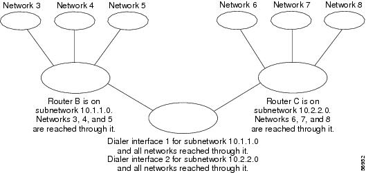
Figure 1 shows a typical application of dialer profiles. Router A has dialer interface 1 for DDR with subnetwork 10.1.1.0, and dialer interface 2 for DDR with subnetwork 10.2.2.0. The IP address for dialer interface 1 is its address as a node in network 10.1.1.0; at the same time, that IP address serves as the IP address of the physical interfaces used by the dialer interface 1. Similarly, the IP address for dialer interface 2 is its address as a node in network 10.2.2.0.
Figure 1 Typical Dialer Profiles Application
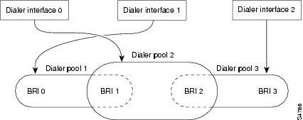
A dialer interface uses only one dialer pool. A physical interface, however, can be a member of one or many dialer pools, and a dialer pool can have several physical interfaces as members.
Figure 2 illustrates the relations among the concepts of dialer interface, dialer pool, and physical interfaces. Dialer interface 0 uses dialer pool 2. Physical interface BRI 1 belongs to dialer pool 2 and has a specific priority in the pool. Physical interface BRI 2 also belongs to dialer pool 2. Because contention is resolved on the basis of priority levels of the physical interfaces in the pool, BRI 1 and BRI 2 must be assigned different priorities in the pool. Perhaps BRI 1 is assigned priority 50 and BRI 2 is assigned priority 100 in dialer pool 2 (a priority of 100 is higher than a priority of 50). BRI 2 has a higher priority in the pool, and its calls will be placed first.
Figure 2 Relations Among Dialer Interfaces, Dialer Pools, and Physical Interfaces
How to Configure Dialer Profiles
To configure dialer profiles, perform the task in the following section:
•
The following tasks can be configured whether you use legacy DDR or dialer profiles. Perform these tasks as needed for your network:
•
•
See the "Verifying the Dynamic Multiple Encapsulations Feature" section later in this chapter for tips on verifying that the feature is running in your network. See the "Configuration Examples Dialer Profiles" section at the end of this chapter for comprehensive configuration examples.
Configuring a Dialer Profile
To configure a dialer profile, perform the tasks in the following sections as required:
•
•
•
•
Configuring a Dialer Interface
Any number of dialer interfaces can be created for a router. Each dialer interface is the complete configuration for a destination subnetwork and any networks reached through it. The router on the destination subnetwork sends traffic on to the appropriate shadowed networks.
To configure a dialer interface, use the following commands beginning in global configuration mode:
Fancy Queueing and Traffic Shaping on Dialer Profile Interfaces
In earlier releases of the Cisco IOS software, fancy queueing and traffic shaping were configured under the physical interfaces, therefore the same queueing or traffic shaping scheme needed to be applied to all users that were sharing the same ISDN link.
Beginning in Cisco IOS Release 12.1, you need only configure the queueing and traffic shaping schemes you desire on the dialer profile interface and the interface will take precedence over those configured on the ISDN B-channel interface. All the per-user encapsulation configuration has been moved to the dialer profile interfaces, separating it from hardware interfaces to make it dynamic and also to make per-user queueing and traffic shaping configuration possible.
Note
See the chapter "Policing and Shaping Overview" in the Cisco IOS Quality of Service Solutions Configuration Guide for more information about FRTS.
Configuring a Map Class
Map-class configuration is optional but allows you to specify different characteristics for different types of calls on a per-call-destination basis. For example, you can specify higher priority and a lower wait-for-carrier time for an ISDN-calls map class than for a modem-calls map class. You can also specify a different speed for some ISDN calls than for other ISDN calls.
A specific map class is tied to a specific call destination by the use of the map-class name in the dialer-string command with the class keyword.
To specify a map class and define its characteristics, use the following commands beginning in global configuration mode:
Note
Configuring the Physical Interfaces
To configure a physical interface, use the following commands beginning in global configuration mode:
Repeat this procedure for additional physical interfaces that you want to use with dialer profiles.
Configuring Dialer Profiles for Routed Protocols
Both legacy DDR and dialer profiles support the following routed protocols: AppleTalk, Banyan VINES, DECnet, IP, Novell Internet Protocol Exchange (IPX), and Xerox Network System (XNS). To configure dialer profiles for a routed protocol, perform the tasks in the relevant section:
•
•
•
•
•
•
Configuring Dialer Profiles for AppleTalk
To configure dialer profiles for AppleTalk, you specify AppleTalk access lists and then configure the dialer interface for dialer profiles, defining the dialer list to be used. Use the dialer-list protocol command to define permit or deny conditions for the entire protocol; for a finer granularity, use the dialer-list protocol command with the list keyword. See the section "Configuring a Dialer Interface" earlier in this chapter for more information about defining dialer lists.
Configuring Dialer Profiles for Banyan VINES
To configure DDR for Banyan VINES, use one of the following commands in global configuration mode:
After you specify VINES standard or extended access lists, configure the dialer interface for dialer profiles, defining the dialer list to be used. Use the dialer-list protocol command to define permit or deny conditions for the entire protocol; for a finer granularity, use the dialer-list protocol command with the list keyword. See the section "Configuring a Dialer Interface" earlier in this chapter for more information about defining dialer lists.
Note
Configuring Dialer Profiles for DECnet
To configure dial-on-demand routing (DDR) for DECnet, use one of the following commands in global configuration mode:
After you specify DECnet standard or extended access lists, configure the dialer interface for dialer profiles, defining the dialer list to be used. Use the dialer-list protocol command to define permit or deny conditions for the entire protocol; for a finer granularity, use the dialer-list protocol command with the list keyword. See the section "Configuring a Dialer Interface" earlier in this chapter for more information about defining dialer lists.
You classify DECnet control packets, including hello packets and routing updates, using one or more of the following commands: dialer-list protocol decnet_router-L1 permit, dialer-list protocol decnet_router-L2 permit, and dialer-list protocol decnet_node permit.
Configuring Dialer Profiles for IP
To configure DDR for IP, use one of the following commands in global configuration mode:
You can now also use simplified IP access lists that use the any keyword instead of the numeric forms of source and destination addresses and masks. Other forms of IP access lists are also available. For more information, see the chapter "IP Services Commands" in the Cisco IOS IP Command Reference.
To use dynamic routing where multiple remote sites communicate with each other through a central site, you might need to disable the IP split horizon feature. Split horizon applies to Routing Information Protocol (RIP), Interior Gateway Routing Protocol (IGRP), and Enhanced IGRP. Depending on which routing protocol is configured, see the chapter "Configuring RIP," "Configuring IGRP," or "Configuring Enhanced IGRP" in this publication. Refer to the chapter "Configuring IP Routing Protocols" in the Cisco IOS IP Configuration Guide for more information.
Configuring Dialer Profiles for Novell IPX
On DDR links for Novell IPX, the link may come up often even when all client sessions are idle because the server sends watchdog or keepalive packets to all the clients approximately every 5 minutes. You can configure a local router or access server to idle out the DDR link and respond to the watchdog packets on behalf of the clients.
To modify the dialer profiles dialer interface configuration for Novell IPX, use the following commands in interface configuration mode:
Configuring XNS over DDR
To configure XNS for DDR, use one of the following commands in global configuration mode:
After you specify an XNS access list, configure the dialer interface for dialer profiles, defining the dialer list to be used. Use the dialer-list protocol command to define permit or deny conditions for the entire protocol; for a finer granularity, use the dialer-list protocol command with the list keyword. See the section "Configuring a Dialer Interface" earlier in this chapter for more information about defining dialer lists.
Configuring Dialer Profiles for Transparent Bridging
The Cisco IOS software supports transparent bridging over both legacy DDR and dialer profiles, and it provides you some flexibility in controlling access and configuring the interface.
To configure dialer profiles for bridging, perform the tasks in the following sections:
•
•
•
•
Defining the Protocols to Bridge
IP packets are routed by default unless they are explicitly bridged; all others are bridged by default unless they are explicitly routed. To bridge IP packets, use the following command in global configuration mode:
If you choose not to bridge another protocol, use the relevant command to enable routing of that protocol. For more information about tasks and commands, refer to the relevant chapter in the appropriate network protocol configuration guide, such as the Cisco IOS AppleTalk and Novell IPX Configuration Guide.
Specifying the Bridging Protocol
You must specify the type of spanning-tree bridging protocol to use and also identify a bridge group. To specify the spanning-tree protocol and a bridge group number, use the following command in global configuration mode:
Router(config)# bridge bridge-group protocol {ieee | dec}
Defines the type of spanning-tree protocol and identifies a bridge group.
The bridge-group number is used when you configure the interface and assign it to a bridge group. Packets are bridged only among members of the same bridge group.
Controlling Access for Bridging
You can control access by defining any transparent bridge packet as interesting, or you can use the finer granularity of controlling access by Ethernet type codes. To control access for DDR bridging, perform one of the following tasks:
•
•
Note
Permitting All Bridge Packets
To identify all transparent bridge packets as interesting, use the following command in global configuration mode:
Router(config)# dialer-list dialer-group protocol bridge permit
Defines a dialer list that treats all transparent bridge packets as interesting.
Controlling Bridging Access by Ethernet Type Codes
To control access by Ethernet type codes, use the following commands in global configuration mode:
For a table of some common Ethernet type codes, see the "Ethernet Type Codes" appendix in the Cisco IOS Bridging and IBM Networking Command Reference.
Configuring an Interface for Bridging
You can perform serial interfaces or ISDN interfaces for DDR bridging. To configure an interface for DDR bridging, complete all the tasks in the following sections:
•
•
•
Specifying the Interface
To specify the interface and enter interface configuration mode, use the following command in global configuration mode:
Router(config)# interface type number
Specifies the serial or ISDN interface and enters interface configuration mode.
Configuring the Destination
You can configure the destination by specifying either of the following:
•
•
To configure the destination for bridging over a specified interface, use the following command in interface configuration mode:
Note
Assigning the Interface to a Bridge Group
Packets are bridged only among interfaces that belong to the same bridge group. To assign an interface to a bridge group, use the following command in interface configuration mode:
Router(config-if)# bridge-group bridge-group
Assigns the specified interface to a bridge group.
Monitoring and Maintaining Dialer Profile Connections
To monitor DDR dialer profile connections, use any of the following commands in privileged EXEC mode:
Configuration Examples Dialer Profiles
The following sections provide three comprehensive configuration examples:
•
•
•
•
Dialer Profile with Inbound Traffic Filter Example
The following example shows a Cisco 5200 series router that has enabled the dialer idle-timeout command with the inbound keyword. This command allows only inbound traffic that conforms to the dialer list to establish a connection and reset the dialer idle timer.
interface Serial0:23no ip addressno ip directed-broadcastencapsulation pppdialer pool-member 1 max-link 2isdn switch-type primary-5essno cdp enableppp authentication chap!interface Dialer0ip address 10.1.1.2 255.255.255.0no ip directed-broadcastencapsulation pppdialer remote-name 2610-2dialer idle-timeout 30 inbounddialer string 2481301dialer pool 1dialer-group 1no cdp enableppp authentication chapppp multilink!access-list 101 permit icmp any anyaccess-list 101 deny ip any anydialer-list 1 protocol ip list 101Dialer Profile for Central Site with Multiple Remote Sites Example
The following example shows a central site that can place or receive calls from three remote sites over four ISDN BRI lines. Each remote site is on a different IP subnet and has different bandwidth requirements; therefore, three dialer interfaces and three dialer pools are defined.
! This is a dialer profile for reaching remote subnetwork 10.1.1.1.interface Dialer1ip address 10.1.1.1 255.255.255.0encapsulation pppdialer remote-name Smalluserdialer string 4540dialer pool 3dialer-group 1! This is a dialer profile for reaching remote subnetwork 10.2.2.2.interface Dialer2ip address 10.2.2.2 255.255.255.0encapsulation pppdialer remote-name Mediumuserdialer string 5264540 class Engdialer load-threshold 50 eitherdialer pool 1dialer-group 2! This is a dialer profile for reaching remote subnetwork 10.3.3.3.interface Dialer3ip address 10.3.3.3 255.255.255.0encapsulation pppdialer remote-name Poweruserdialer string 4156884540 class Engdialer hold-queue 10dialer load-threshold 80dialer pool 2dialer-group 2! This map class ensures that these calls use an ISDN speed of 56 kbps.map-class dialer Engisdn speed 56interface BRI0encapsulation PPP! BRI 0 has a higher priority than BRI 1 in dialer pool 1.dialer pool-member 1 priority 100ppp authentication chapinterface BRI1encapsulation pppdialer pool-member 1 priority 50dialer pool-member 2 priority 50! BRI 1 has a reserved channel in dialer pool 3; the channel remains inactive! until BRI 1 uses it to place calls.dialer pool-member 3 min-link 1ppp authentication chapinterface BRI2encapsulation ppp! BRI 2 has a higher priority than BRI 1 in dialer pool 2.dialer pool-member 2 priority 100ppp authentication chapinterface BRI3encapsulation ppp! BRI 3 has the highest priority in dialer pool 2.dialer pool-member 2 priority 150ppp authentication chapDialer Profile for ISDN BRI Backing Up Two Leased Lines Example
The following example shows the configuration of a site that backs up two leased lines using one BRI. Two dialer interfaces are defined. Each serial (leased line) interface is configured to use one of the dialer interfaces as a backup. Both of the dialer interfaces use BRI 0, and BRI 0 is a member of the two dialer pools. Thus, BRI 0 can back up two different serial interfaces and can make calls to two different sites.
interface dialer0ip unnumbered loopback0encapsulation pppdialer remote-name Remote0dialer pool 1dialer string 5551212dialer-group 1interface dialer1ip unnumbered loopback0encapsulation pppdialer remote-name Remote1dialer pool 2dialer string 5551234dialer-group 1interface bri 0encapsulation PPPdialer pool-member 1dialer pool-member 2ppp authentication chapinterface serial 0ip unnumbered loopback0backup interface dialer0backup delay 5 10interface serial 1ip unnumbered loopback0backup interface dialer1backup delay 5 10Dynamic Multiple Encapsulations over ISDN Example
The following example shows a network access server named NAS1 with dialer profiles and LAPB, X.25, and PPP encapsulations configured. Although the BRI0 D interface uses X.25 encapsulation, the actual encapsulations running over the ISDN B channels are determined by the encapsulations configured on the profile interfaces bound to them.
When an ISDN B channel connects to remote user RU2 using CLID 60043, Dialer1 is bound to this ISDN B channel by CLID binding. The protocol used is PPP; the X.25 configuration on the
D interface has no effect. Because the ppp authentication chap command is configured, even though the binding is done by CLID, PPP authentication is still performed over the name RU2 before the protocol is allowed to proceed.The Dialer2 interface uses DNIS-plus-ISDN-subaddress binding and is bound to a B channel with an incoming call with DNIS 60045 and ISDN subaddress 12345. Also note that the High-Level Data Link Control (HDLC) encapsulation has no username associated. It is no longer necessary to configure the dialer remote-name command, as in the previous dialer profile model.
When there is an ISDN B-channel connection to remote user RU1 using CLID 60036, LAPB encapsulation will run on this connection once CLID binding to Dialer0 takes place. This connection will operate as a standalone link independent of other activities over other ISDN B channels.
version xx.xservice timestamps debug datetime msecservice timestamps log datetime msecservice password-encryptionservice udp-small-serversservice tcp-small-servers!virtual-profile virtual-template 1virtual-profile aaa!hostname NAS1!aaa new-modelaaa authentication ppp default radiusaaa authorization network radiusenable secret 5 $1$0Ced$YYJJl2p8f94lc/.JSgw8n1enable password 7 153D19270D2E!username RU1 password 7 11260B2E1E16username RU2 password 7 09635C221001no ip domain-lookupip domain-name cisco.comip name-server 192.168.30.32ip name-server 172.16.2.132isdn switch-type basic-5ess!interface Virtual-Template 1encapsulation pppppp authentication chap!interface Ethernet0ip address 172.21.17.11 255.255.255.0no ip mroute-cacheno cdp enable!interface Serial0ip address 10.2.2.1 255.0.0.0shutdownclockrate 56000ppp authentication chap!interface Serial1ip address 10.0.0.1 255.0.0.0shutdown!interface BRI0description PBX 60035no ip addressencapsulation x25no ip mroute-cacheno keepalivedialer pool-member 1dialer pool-member 2!interface Dialer0ip address 10.1.1.1 255.0.0.0encapsulation lapb dce multino ip route-cacheno ip mroute-cacheno keepalivedialer remote-name RU1dialer idle-timeout 300dialer string 60036dialer caller 60036dialer pool 1dialer-group 1no fair-queue!interface Dialer1ip address 10.1.1.1 255.0.0.0encapsulation pppno ip route-cacheno ip mroute-cachedialer remote-name RU2dialer string 60043dialer caller 60043dialer pool 2dialer-group 1no fair-queueno cdp enableppp authentication chap!interface Dialer2ip address 10.1.1.1 255.0.0.0encapsulation hdlcdialer called 60045:12345dialer pool 1dialer-group 1fair-queue!radius-server host 172.19.61.87radius-server key foobarsnmp-server community public RO!line con 0exec-timeout 0 0line aux 0transport input allline vty 0 4password 7 10611B320C13login!endVerifying the Dynamic Multiple Encapsulations Feature
To see statistics on each physical interface bound to the dialer interface, and to verify dialer interfaces configured for binding, use the show interfaces EXEC command. Look for the reports "Bound to:" and "Interface is bound to..." while remembering that this feature applies only to ISDN.
Router# show interfaces dialer0Dialer0 is up, line protocol is upHardware is UnknownInternet address is 10.1.1.2/8MTU 1500 bytes, BW 64 Kbit, DLY 20000 usec, rely 255/255, load 1/255Encapsulation PPP, loopback not setDTR is pulsed for 1 seconds on resetInterface is bound to BRI0:1Last input 00:00:38, output never, output hang neverLast clearing of "show interface" counters 00:05:36Queueing strategy: fifoOutput queue 0/40, 0 drops; input queue 0/75, 0 drops5 minute input rate 0 bits/sec, 0 packets/sec5 minute output rate 0 bits/sec, 0 packets/sec38 packets input, 4659 bytes34 packets output, 9952 bytesBound to:BRI0:1 is up, line protocol is upHardware is BRIMTU 1500 bytes, BW 64 Kbit, DLY 20000 usec, rely 255/255, load 1/255Encapsulation PPP, loopback not set, keepalive not setInterface is bound to Dialer0 (Encapsulation PPP)LCP Open, multilink OpenLast input 00:00:39, output 00:00:11, output hang neverLast clearing of "show interface" counters neverQueueing strategy: fifoOutput queue 0/40, 0 drops; input queue 0/75, 0 drops5 minute input rate 0 bits/sec, 0 packets/sec5 minute output rate 0 bits/sec, 0 packets/sec78 packets input, 9317 bytes, 0 no bufferReceived 65 broadcasts, 0 runts, 0 giants, 0 throttles0 input errors, 0 CRC, 0 frame, 0 overrun, 0 ignored, 0 abort93 packets output, 9864 bytes, 0 underruns0 output errors, 0 collisions, 7 interface resets0 output buffer failures, 0 output buffers swapped out4 carrier transitionsAt the end of the Dialer0 display, the show interfaces command is executed on each physical interface bound to it.
In the next example, the physical interface is the B1 channel of the BRI0 link. This example also illustrates that the output under the B channel keeps all hardware counts that are not displayed under any logical or virtual access interface. The line in the report that states "Interface is bound to Dialer0 (Encapsulation LAPB)" indicates that this B interface is bound to the dialer 0 interface and that the encapsulation running over this connection is LAPB, not PPP, which is the encapsulation configured on the D interface and inherited by the B channel.
Router# show interfaces bri0:1BRI0:1 is up, line protocol is upHardware is BRIMTU 1500 bytes, BW 64 Kbit, DLY 20000 usec, rely 255/255, load 1/255Encapsulation PPP, loopback not set, keepalive not setInterface is bound to Dialer0 (Encapsulation LAPB)LCP Open, multilink OpenLast input 00:00:31, output 00:00:03, output hang neverLast clearing of "show interface" counters neverQueueing strategy: fifoOutput queue 0/40, 0 drops; input queue 0/75, 0 drops5 minute input rate 0 bits/sec, 1 packets/sec5 minute output rate 0 bits/sec, 1 packets/sec110 packets input, 13994 bytes, 0 no bufferReceived 91 broadcasts, 0 runts, 0 giants, 0 throttles0 input errors, 0 CRC, 0 frame, 0 overrun, 0 ignored, 0 abort135 packets output, 14175 bytes, 0 underruns0 output errors, 0 collisions, 12 interface resets0 output buffer failures, 0 output buffers swapped out8 carrier transitionsCisco and the Cisco Logo are trademarks of Cisco Systems, Inc. and/or its affiliates in the U.S. and other countries. A listing of Cisco's trademarks can be found at www.cisco.com/go/trademarks. Third party trademarks mentioned are the property of their respective owners. The use of the word partner does not imply a partnership relationship between Cisco and any other company. (1005R)
Any Internet Protocol (IP) addresses and phone numbers used in this document are not intended to be actual addresses and phone numbers. Any examples, command display output, network topology diagrams, and other figures included in the document are shown for illustrative purposes only. Any use of actual IP addresses or phone numbers in illustrative content is unintentional and coincidental.
© 2007-2009 Cisco Systems, Inc. All rights reserved.