-
Dial Technologies Configuration Guide, Cisco IOS Release 15.2S
- Part 1: Dial Interfaces, Controllers, and Lines
-
Part 2 - Modem Configuration and Management
-
Overview of Modem Interfaces
-
Configuring and Managing Integrated Modems
-
1- and 2-Port V.90 Modem WICs for Cisco 2600 and Cisco 3600 Series Multiservice Platforms
-
Call Tracker show Commands Extensions
-
Cisco NM-8AM-V2 and NM-16AM-V2 Analog Modem Network Modules with V.92
-
MICA and NextPort Modem Tech-Support Command Additions
-
PIAFS Wireless Data Protocol Version 2.1 for Cisco MICA Modems
-
V.92 and V.44 Support for Digital Modems
-
V.92 Modem on Hold for Cisco AS5300 and Cisco AS5800 Universal Access Servers
-
V.92 Modem on Hold for Cisco AS5350, Cisco AS5400, and Cisco AS5850 Universal Gateways and Cisco AS5800 Universal Access Servers
-
V.92 Quick Connect for Cisco AS5300 and Cisco AS5800 Universal Access Servers
-
V.92 Quick Connect for Cisco AS5350, Cisco AS5400, and Cisco AS5850 Universal Gateways and Cisco AS5800 Universal Access Servers
-
V.92 Reporting Using RADIUS Attribute v.92-info
-
Configuring and Managing Cisco Access Servers and Dial Shelves
-
Configuring and Managing External Modems
-
Modem Signal and Line States
-
Creating and Using Modem Chat Scripts
-
Cisco Modem User Interface
-
Modem Script and System Script Support in Large-Scale Dial-Out
-
- Part 3 - ISDN Configuration
- Part 4 - Signaling Configuration
-
Part 5 - Dial-on-Demand Routing Configuration
-
Preparing to Configure DDR
-
Configuring Legacy DDR Spokes
-
Configuring Legacy DDR Hubs
-
Configuring Peer-to-Peer DDR with Dialer Profiles
-
Dialer Map VRF-Aware for an MPLS VPN
-
Dialer Persistent
-
PPPoE Client DDR Idle-Timer
-
Redial Enhancements
-
Rotating Through Dial Strings
-
Configuring Dialer CEF
-
CEF Support for Dialer Profiles on Cisco 7500 Routers
-
Configuring Snapshot Routing
-
- Part 6: Dial-Backup Configuration
- Part 7: Dial-Related Addressing Services
- Part 8: Virtual Templates and Profiles
-
Part 9: PPP Configuration
-
Configuring Asynchronous SLIP and PPP
-
Optimized PPP Negotiation
-
Customer Profile Idle Timer Enhancements for Interesting Traffic
-
Multiclass Multilink PPP
-
Configuring Media-Independent PPP and Multilink PPP
-
PPP/MLP MRRU Negotiation Configuration
-
Troubleshooting Enhancements for Multilink PPP over ATM Link Fragmentation and Interleaving
-
Multichassis Multilink PPP
-
- Part 10: Callback and Bandwidth Allocation Configuration
- Part 11: Dial Access Specialized Features
- Appendix
 Feedback
Table Of Contents
Configuring Resource Pool Management
Components of Incoming and Outgoing Call Management
Data over Voice Bearer Services
Incoming Call Preauthentication
RPM Standalone Network Access Server
Base Session and Overflow Session Limits
VPDN Session and Overflow Session Limits
VPDN MLP Bundle and Links-per-Bundle Limits
Additional Information About Cisco RPM
Configuring Discriminator Profiles
Configuring Default Customer Profiles
Configuring Customer Profiles Using Backup Customer Profiles
Configuring Customer Profiles for Using DoVBS
Configuring a Customer Profile Template
Typical Template Configuration
Verifying Template Configuration
Placing the Template in the Customer Profile
Counting VPDN Sessions by Using VPDN Profiles
Limiting the Number of MLP Bundles in VPDN Groups
Configuring Switched 56 over CT1 and RBS
Verifying Call Counters for a Customer Profile
Verifying Call Counters for a Discriminator Profile
Verifying Call Counters for a Resource Group
Verifying Call Counters for a DNIS Group
Verifying Call Counters for a VPDN Profile
Verifying Load Sharing and Backup
Successful Resource Pool Connection
Troubleshooting DNIS Group Problems
Troubleshooting Call Discriminator Problems
Troubleshooting Customer Profile Counts
Troubleshooting Resource Group Counts
Troubleshooting RPM/VPDN Connection
Troubleshooting Customer/VPDN Profile
Troubleshooting VPDN Profile Limits
Troubleshooting VPDN Group Limits
Troubleshooting VPDN Endpoint Problems
Configuration Examples for RPM
Standard Configuration for RPM Example
Customer Profile Configuration for DoVBS Example
DNIS Discriminator Profile Example
CLID Discriminator Profile Example
Direct Remote Services Configuration Example
VPDN Load Sharing and Backing Up Between Multiple HGW/LNSs Example
Configuring Resource Pool Management
This chapter describes the Cisco Resource Pool Management (RPM) feature. It includes the following main sections:
•
Configuration Examples for RPM
To identify the hardware platform or software image information associated with a feature, use the Feature Navigator on Cisco.com to search for information about the feature, or refer to the software release notes for a specific release. For more information, see the "Identifying Supported Platforms" section in the "Using Cisco IOS Software" chapter.
For a complete description of the commands mentioned in this chapter, refer to the Cisco IOS Dial Technologies Command Reference, Release 12.2. To locate documentation of other commands that appear in this chapter, use the command reference master index or search online.
RPM Overview
Cisco RPM enables telephone companies and Internet service providers (ISPs) to share dial resources for wholesale and retail dial network services. With RPM, telcos and ISPs can count, control, and manage dial resources and provide accounting for shared resources when implementing different service-level agreements.
You can configure RPM in a single, standalone Cisco network access server (NAS) by using RPM or, optionally, across multiple NAS stacks by using one or more external Cisco Resource Pool Manager Servers (RPMS).
Cisco RPM gives data network service providers the capability to do the following:
•
•
•
•
•
•
Note
Components of Incoming and Outgoing Call Management
Cisco RPM manages both incoming calls and outgoing sessions. Cisco RPM differentiates dial customers through configured customer profiles based on the DNIS and call type determined at the time of an incoming call.
The components of incoming call management in the Cisco RPM are described in the following sections:
You can use Cisco RPM to answer all calls and differentiate customers by using VPDN profiles and groups. The components of outgoing session management in the Cisco RPM are described in the following sections:
Note
Configured DNIS groups and resource data can be associated to customer profiles. These customer profiles are selected by the incoming call DNIS number and call type and then used to identify resource allocations based on the associated resource groups and defined resource services.
After the call is answered, customer profiles can also be associated with VPDN groups so the configured VPDN sessions and other data necessary to set up or reject a VPDN session are applied to the answered calls. VPDN group data includes associated domain name or DNIS, IP addresses of endpoints, maximum sessions per endpoint, maximum Multilink PPP (MLP) bundles per VPDN group, maximum links per MLP bundle, and other tunnel information.
Customer Profile Types
There are three types of customer profiles in Cisco RPM, which are described in the following sections:
Additionally, you can create a customer profile template and associate it with a customer profile; it is then integrated into the customer profile.
Customer Profiles
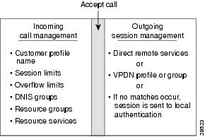
A customer profile defines how and when to answer a call. Customer profiles include the following components (see Figure 1):
•
•
•
•
•
•
•
•
•
Figure 1 Components of a Customer Profile
The incoming side of the customer profile determines if the call will be answered using parameters such as DNIS and call type from the assigned DNIS group and session limits. The call is then assigned the appropriate resource within the resource group defined in the customer profile. Each configured customer profile includes a maximum allowed session value and an overflow value. As sessions are started and ended, session counters are incremented and decremented so customer status is kept current. This information is used to monitor the customer resource limit and determine the appropriate call treatment based on the configured session limits.
The outgoing side of the customer profile directs the answered call to the appropriate destination:
Note
•
•
Default Customer Profiles
Default customer profiles are identical to standard customer profiles, except that they do not have any associated DNIS groups. Default customer profiles are created using the reserved keyword default for the DNIS group.
Default customer profiles are used to provide session counting and resource assignment to incoming calls that do not match any of the configured DNIS groups. Although specific resources and DNIS groups can be assigned to customer profiles, default customer profiles allow resource pooling for the calls that do not match the configured DNIS groups or where the DNIS is not provided. Retail dial services and domain-based VPDN use default customer profiles.
When multiple default customer profiles are used, the call type (speech, digital, V.110, or V.120) of the default DNIS group is used to identify which default customer profile to use for an incoming call. At most, four default profiles (one for each call type) can be configured.
Note
Backup Customer Profiles
Backup customer profiles are customer profiles configured locally on the Cisco NAS and are used to answer calls based on a configured allocation scheme when the link between the Cisco NAS and Cisco RPMS is disabled. See the section "Configuring Customer Profiles Using Backup Customer Profiles" for more information about configuring backup customer profiles.
Customer Profile Template
With RPM, users can also implement wholesale dial services without using VPDN tunnels to complete dial-in calls to destinations of the end customer. This capability is accomplished with components of the AAA groups and the PPP configurations.
The AAA group provides IP addresses of AAA servers for authentication and accounting. The PPP configurations allow users to configure the Cisco IOS PPP feature set on each customer profile. In this current implementation, PPP configuration is based on the following:
•
•
•
Note
To add PPP configurations to a customer profile, you must create a customer profile template. Once you create the template and associate it with a customer profile using the source template command, it is integrated into the customer profile.
The RPM customer profile template for the PPP command set, when used with the Cisco IOS feature, Server Groups Selected by DNIS, presents a strong single NAS solution for providers of wholesale dial services, as follows:
•
•
•
The section "Configuring a Customer Profile Template" later in this chapter describes how to create a customer profile template so that you can configure the Cisco IOS PPP features on a customer profile, but this section does not list the existing PPP command set. For information about the PPP command set, refer to the Cisco IOS Dial Technologies Command Reference.
DNIS Groups
A DNIS group is a configured list of DNIS called party numbers that correspond to the numbers dialed to access particular customers, service offerings, or both. For example, if a customer from phone number 000-1234 calls a number 000-5678, the DNIS provides information on the number dialed—000-5678.
Cisco RPM checks the DNIS number of inbound calls against the configured DNIS groups, as follows:
•
•
•
CLID Groups
A CLID group is a configured list of CLID calling party numbers. The CLID group specifies a list of numbers to reject if the group is associated with a call discriminator. For example, if a customer from phone number 000-1234 calls a number 000-5678, the CLID provides information on the calling party number—000-1234.
A CLID can be associated with only one CLID group.
Call Types
Call types from calls originating from ISDN, SS7, and CAS (CT1, CT3, and CE1) are used to assign calls to the appropriate resource. Call types for ISDN and SS7 are based on Q.931 bearer capability. Call types for CAS are assigned based on static channel configuration.
Supported call types are as follows:
•
•
•
•
Note
Resource Groups
Cisco RPM enables you to maximize the use of available shared resources within a Cisco NAS for various resource allocation schemes to support service-level agreements. Cisco RPM allows you to combine your Cisco NAS resource groups with call types (speech, digital, V.110, and V.120) and optional resource modem services. Resource groups and services are configured for customer profiles and assigned to incoming calls through DNIS groups and call types.
Resource groups have the following characteristics:
•
•
•
–
–
Resource assignments contain combinations of Cisco NAS resource groups, optional resource modem services, and call types. The NAS resources in resource groups that have not been assigned to a customer profile will not be used.
Note
Resource Services
A resource service contains a finite series of resource command strings that can be used to help dynamically configure an incoming connection. Services supported by a resource group are determined by the combination of hardware and firmware installed. Currently, resource service options can be configured and applied to resource groups. Resource services can be defined to affect minimum and maximum speed, modulation, error correction, and compression, as shown in Table 1.
VPDN Groups
The VPDN group contains the data required to build a VPDN tunnel from the RPM NAS LAC to the LNS. In the context of RPM, VPDN is authorized by first associating a customer profile with a VPDN group, and second by associating the VPDN group to the DNIS group used for that customer profile. VPDN group data includes the endpoint IP addresses.
Cisco RPM enables you to specify multiple IP endpoints for a VPDN group, as follows:
•
•
•
•
The VPDN group provides call management by allowing limits to be applied to both the number of MLP bundles per tunnel and the number of links per MLP bundle. Limits can also restrict the number of sessions per IP endpoint. If you require more granular control of VPDN counters, use VPDN profiles.
VPDN Profiles
VPDN profiles allow session and overflow limits to be imposed for a particular customer profile. These limits are unrelated to the limits imposed by the customer profile. A customer profile is associated with a VPDN profile. A VPDN profile is associated with a VPDN group. VPDN profiles are required only when these additional counters are required for VPDN usage per customer profile.
Call Treatments
Call treatment determines how calls are handled when certain events require the call to be rejected. For example, if the session and overflow limits for one of your customers have been exceeded, any additional calls will receive a busy signal (see Table 2).
Details on RPM Call Processes
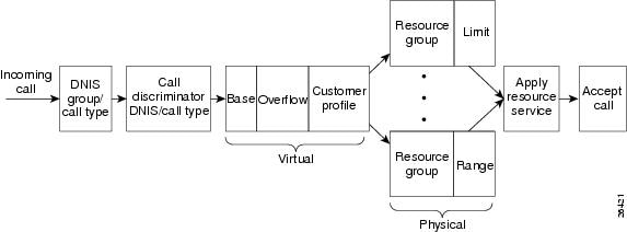
On the incoming call management of the customer profile, the following sequence occurs to determine if a call is answered:
1.
2.
3.
4.
5.
6.
See Figure 2 for a graphical illustration of the RPM call processes.
Figure 2 Incoming Call Management: RPM Functional Description
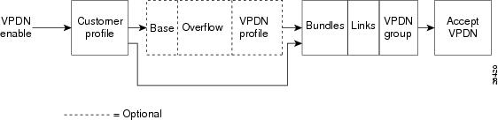
After the call is answered and if VPDN is enabled, Cisco RPM checks the customer profile for an assigned VPDN group or profile. The outgoing session management of the customer profile directs the answered call to the appropriate destination (see Figure 3), as follows:
Note
•
•
Figure 3 Outgoing Call Management: RPM Functional Description for VPDN Profiles and Groups
If a VPDN profile is found, the limits are checked, as follows:
•
•
If a VPDN group is found within the customer profile, the VPDN group data is used to build a VPDN tunnel, as follows:
•
•
If no VPDN profile is assigned to the customer profile and VPDN is enabled, non-RPM VPDN service is attempted. If the attempt fails, the call is processed as a retail dial service call if local AAA service is available.
Accounting Data
You can generate accounting data for network dial service usage in NAS AAA attribute format.
You can configure the Cisco NAS to generate AAA accounting records for access to external AAA server option. The accounting start and stop records in AAA attribute format are sent to the external AAA server using either RADIUS server hosts or TACACS+ protocols for accounting data storage. Table 3 lists the new fields in the AAA accounting packets.
Data over Voice Bearer Services
DoVBS is a dial service that uses a customer profile and an associated resource group of digital resources to direct data calls with a speech call type to HDLC controllers.
To support ISDN DoVBS, use a DNIS group and a configured customer profile to direct the speech call to the appropriate digital resource.
The resource group assigned to this customer profile will be "digital resources" and will also have a call type of speech, so the call will terminate on an HDLC controller rather than a modem.
Call Discriminator Profiles
The Cisco RPM CLID/DNIS Call Discriminator feature lets you specify a list of calling party numbers to be rejected for inbound calls. This Cisco IOS Release 12.2 CLID/DNIS call screening feature expands previous call screening features in Cisco RPM. CLID/DNIS call screening provides an additional way to screen calls on the basis of CLID/DNIS for both local and remote RPM.
Cisco RPM CLID/DNIS Call Discriminator profiles enable you to process calls differently on the basis of the call type and CLID combination. Resource pool management offers a call discrimination feature that rejects calls on the basis of a CLID group and a call type filter. When a call arrives at the NAS, the CLID and the call type are matched against a table of disallowed calls. If the CLID and call type match entries in this table, the call is rejected before it is assigned Cisco NAS resources or before any other Cisco RPM processing occurs. This is called precall screening.
Precall screening decides whether the call is allowed to be processed. You can use the following types of discriminators to execute precall screening:
•
•
•
If you configure a discriminator with a CLID group, the calling party numbers specified in the group are rejected. CLID gives you information about the caller.
Similarly, if you configure a discriminator with a DNIS group, the called party numbers specified in the group are rejected.
The Cisco RPM CLID/DNIS Call Discriminator Feature is independent of ISDN or DNIS screening done by other subsystems. ISDN or DNIS screening and Cisco RPM CLID/DNIS screening can both be present in the same system. Both features are executed if configured. Similarly, if DNIS Preauthorization using AAA is configured, it is present in addition to Cisco RPM CLID/DNIS screening. Refer to the Cisco IOS Security Configuration Guide for more information about call preauthorization.
In Cisco RPM CLID/DNIS screening, the discriminator can be a CLID discriminator, a DNIS discriminator, or a discriminator that screens on both the CLID and DNIS. The resulting discrimination logic is:
•
•
•
Figure 4 shows how call discrimination can be used to restrict a specific DNIS group to only modem calls by creating call discrimination settings for the DNIS group and the other supported call types (digital, V.110, and V.120).
Figure 4 Call Discrimination
Incoming Call Preauthentication
With ISDN PRI or channel-associated signaling (CAS), information about an incoming call is available to the NAS before the call is connected. The available call information includes:
•
•
•
The Preauthentication with ISDN PRI and Channel-Associated Signalling feature introduced in Cisco IOS Release 12.2 allows a Cisco NAS to decide—on the basis of the DNIS number, the CLID number, or the call type—whether to connect an incoming call.
When an incoming call arrives from the public network switch, but before it is connected, this feature enables the NAS to send the DNIS number, CLID number, and call type to a RADIUS server for authorization. If the server authorizes the call, the NAS accepts the call. If the server does not authorize the call, the NAS sends a disconnect message to the public network switch to reject the call.
The Preauthentication with ISDN PRI and Channel-Associated Signalling feature offers the following benefits:
•
•
•
For more information about the Preauthentication with ISDN PRI and Channel-Associated Signalling feature, refer to the Cisco IOS Security Configuration Guide.
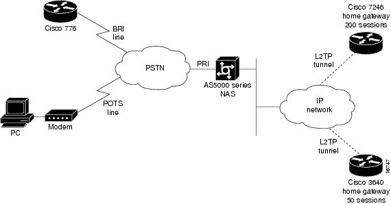
RPM Standalone Network Access Server
A single NAS using Cisco RPM can provide the following:
•
•
•
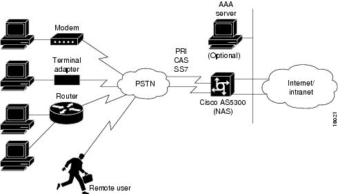
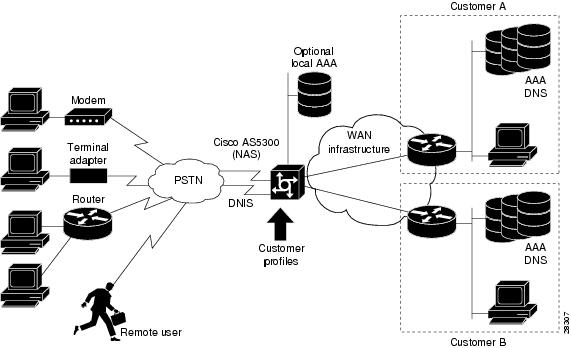
Figure 5 and Figure 6 show multiple connections to a Cisco AS5300 NAS. Incoming calls to the NAS can use ISDN PRI signaling, CAS, or the SS7 signaling protocol. Figure 5 shows incoming calls that are authenticated locally for retail dial services or forwarded through VPDN tunnels for wholesale dial services.
Note
Figure 5 Retail Dial Service Using RPM
Figure 6 shows a method of implementing wholesale dial services without using VPDN tunnels by creating individual customer profiles that consist of AAA groups and PPP configurations. The AAA groups provide IP addresses of AAA servers for authentication and accounting. The PPP configurations enable you to set different PPP parameter values on each customer profile. A customer profile typically includes the following PPP parameters:
•
•
•
•
Note
Figure 6 Resource Pool Management with Direct Remote Services
Call Processing
For call processing, incoming calls are matched to a DNIS group and the customer profile associated with that DNIS group. If a match is found, the customer profile session and overflow limits are applied and if available, the required resources are allocated. If a DNIS group is not found, the customer profile associated with the default DNIS group is used. The call is rejected if a customer profile using the default DNIS group cannot be found.
After the call is answered and if VPDN is enabled, the Cisco RPM checks the customer profile for an assigned VPDN group or profile. If a VPDN group is found, Cisco RPM authorizes VPDN by matching the group domain name or DNIS with the incoming call. If a match is found, VPDN profile session and overflow limits are applied, and, if the limits are not exceeded, tunnel negotiation begins. If the VPDN limits are exceeded, the call is disconnected.
If no VPDN profile is assigned to the customer profile and VPDN is enabled, non-RPM VPDN service will be attempted. If it fails, the call is processed as a retail dial service call if local AAA service is available.
Base Session and Overflow Session Limits
Cisco RPM enables you to set base and overflow session limits in each customer profile. The base session limit determines the maximum number of nonoverflow sessions supported for a customer profile. When the session limit is reached, if overflow sessions are not enabled, any new calls are rejected. If overflow sessions are enabled, new sessions up to the session overflow limit are processed and marked as overflow for call handling and accounting.
The session overflow limit determines the allowable number of sessions above the session limit. If the session overflow limit is greater than zero, overflow sessions are enabled and the maximum number of allowed sessions is the session limit plus the session overflow limit. While the session overflow limit has been reached, any new calls are rejected. Table 4 summarizes the effects of session and session overflow limits.
Enabling overflow sessions is useful for allocating extra sessions for preferred customers at premium rates. Overflow sessions can also be useful for encouraging customers to adequately forecast bandwidth usage or for special events when normal session usage is exceeded. For example, if a customer is having a corporate-wide program and many people are expected to request remote access, you could enable many overflow sessions and charge a premium rate for the excess bandwidth requirements.
Note
VPDN Session and Overflow Session Limits
Cisco RPM enables you to configure base and overflow session limits per VPDN profile for managing VPDN sessions.
Note
The base VPDN session limit determines the maximum number of nonoverflow sessions supported for a VPDN profile. When the VPDN session limit is reached, if overflow sessions are not enabled, any new VPDN calls using the VPDN profile sessions are rejected. If overflow sessions are enabled, new sessions up to the session overflow limit are processed and marked as overflow for VPDN accounting.
The VPDN session overflow limit determines the number of sessions above the session limit allowed in the VPDN group. If the session overflow limit is greater than zero, overflow sessions are enabled and the maximum number of allowed sessions is the session limit plus the session overflow limit. While the session overflow limit has been reached, any new calls are rejected.
Enabling VPDN overflow sessions is useful for allocating extra sessions for preferred customers at premium rates. Overflow sessions are also useful for encouraging customers to adequately forecast bandwidth usage or for special events when normal session usage is exceeded. For example, if a customer is having a corporate-wide program and many people are expected to request remote access, you could enable many overflow sessions and charge a premium rate for the extra bandwidth requirements.
VPDN MLP Bundle and Links-per-Bundle Limits
To ensure that resources are not consumed by a few users with MLP connections, Cisco RPM also enables you to specify the maximum number of MLP bundles that can open in a VPDN group. In addition, you can specify the maximum number of links for each MLP bundle.
For example, if standard ISDN users access the VPDN profile, limit this setting to two links per bundle. If video conferencing is used, increase this setting to accommodate the necessary bandwidth (usually six links). These limits have no overflow option and are configured under the VPDN group component.
VPDN Tunnel Limits
For increased VPDN tunnel management, Cisco RPM enables you to set an IP endpoint session limit for each IP endpoint. IP endpoints are configured for VPDN groups.
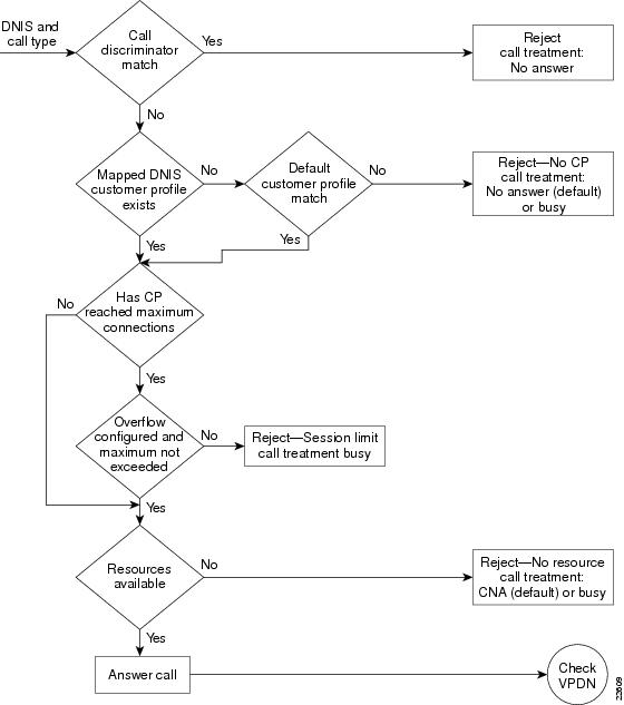
Figure 7 and Figure 8 show logical flowcharts of RPM call processing for a standalone NAS with and without the RPM Direct Remote Services feature.
Figure 7 RPM Call-Processing Flowchart for a Standalone Network Access Server
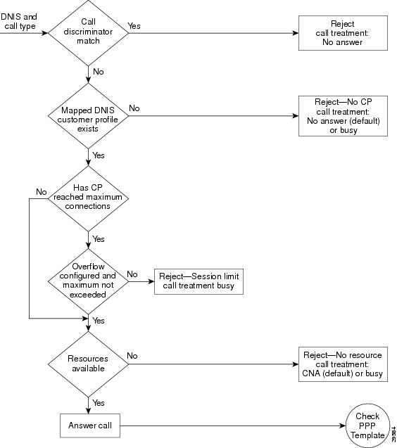
Figure 8 Flowchart for a Standalone Network Access Server with RPM Direct Remote Services
RPM Using the Cisco RPMS
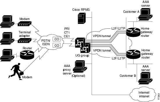
Figure 9 shows a typical resource pooling network scenario using RPMS.
Figure 9 RPM Scenario Using RPMS
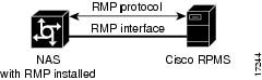
Resource Manager Protocol
Resource Manager Protocol (RMP) is a robust, recoverable protocol used for communication between the Cisco RPMS and the NAS. Each NAS client uses RMP to communicate resource management requests to the Cisco RPMS server. RPMS also periodically polls the NAS clients to query their current call information or address error conditions when they occur. RMP also allows for protocol attributes that make it extensible and enable support for customer billing requirements.
Figure 10 shows the relationship of Cisco RPM CLID/DNIS Call Discriminator Feature and RMP.
Figure 10 Cisco RPM CLID/DNIS Call Discriminator Feature and RMP
Note
Direct Remote Services
Direct remote services is an enhancement to Cisco RPM implemented in Cisco IOS Release 12.0(7)T that enables service providers to implement wholesale dial services without using VPDN tunnels. A customer profile that has been preconfigured with a PPP template to define the unique PPP services for the wholesale dial customer is selected by the incoming DNIS and call type. At the same time, the DNIS is used to select AAA server groups for authentication/authorization and for accounting for the customer.
PPP Common Configuration Architecture (CCA) is the new component of the RPM customer profile that enables direct remote services. The full PPP command set available in Cisco IOS software is configurable per customer profile for wholesale dial applications. A customer profile typically includes the following PPP parameters:
•
•
•
•
The AAA session information is selected by the incoming DNIS. AAA server lists provide the IP addresses of AAA servers for authentication, authorization, and accounting in the wholesale local network of the customer. The server lists for both authentication and authorization and for accounting contain the server addresses, AAA server type, timeout, retransmission, and keys per server.
When direct remote services is implemented on a Cisco NAS, the following sequence occurs:
1.
2.
–
–
–
3.
–
–
–
Note
RPM Process with RPMS and SS7
For information on SS7 implementation for RPM, refer to the document Cisco Resource Pool Manager Server 1.0 SS7 Implementation.
Additional Information About Cisco RPM
For more information about Cisco RPM, see the following documents:
•
•
•
•
•
•
•
•
•
•
•
•
•
•
•
•
•
•
How to Configure RPM
Read and comply with the following restrictions and prerequisites before beginning RPM configuration:
•
•
•
•
•
•
•
•
•
•
The following tasks must be performed before configuring RPM:
•
–
–
–
–
–
Refer to the document Configuring the NAS for Basic Dial Access for more information.
To configure your NAS for RPM, perform the following tasks:
•
•
•
•
•
•
•
•
•
•
•
•
•
•
•
See the section "Troubleshooting RPM" later in this chapter for troubleshooting tips. See the section "Configuration Examples for RPM" at the end of this chapter for examples of how to configure RPM in your network.
Enabling RPM
To enable RPM, use the following commands beginning in global configuration mode:
Note
Configuring DNIS Groups
This configuration task is optional.
To configure DNIS groups, use the following commands beginning in global configuration mode:
For default DNIS service, no DNIS group configuration is required. The following characteristics and restrictions apply to DNIS group configuration:
•
•
•
•
Creating CLID Groups
You can add multiple CLID groups to a discriminator profile. You can organize CLID numbers for a customer or service type into a CLID group. Add all CLID numbers into one CLID group, or subdivide the CLID numbers using criteria such as call type, geographical location, or division. To create CLID groups, use the following commands beginning in global configuration mode:
Configuring Discriminator Profiles
Discriminator profiles enable you to process calls differently on the basis of the call type and CLID/DNIS combination. The "Call Discriminator Profiles" section earlier in this chapter describes the different types of discriminator profiles that you can create.
To configure discriminator profiles for RPM implementation, use the following commands beginning in global configuration mode:
To verify discriminator profile settings, use the following commands:
Step 1
If you enter the show resource-pool discriminator command without including a call discriminator name, a list of all current call discriminator profiles appears.
If you enter a call discriminator profile name with the show resource-pool discriminator command, the number of calls rejected by the selected call discriminator appears.
Router# show resource-pool discriminatorList of Call Discriminator Profiles:deny_CLIDRouter# show resource-pool discriminator deny_CLID1 calls rejectedStep 2
Router# show dialer [interface] type number
Configuring Resource Groups
To configure resource groups, use the following commands beginning in global configuration mode:
For external Cisco RPMS environments, configure resource groups on the NAS before defining them on external RPMS servers.
For standalone NAS environments, first configure resource groups before using them in customer profiles.
Resource groups can apply to multiple customer profiles.
Note
Configuring Service Profiles
To configure service profiles, use the following commands beginning in global configuration mode:
Service profiles are used to configure modem service parameters for Nextport and MICA technologies modems, and support speech, digital, V.110, and V.120 call types. Error-correction and compression are hidden parameters that may be included in a service profile.
Configuring Customer Profiles
To configure customer profiles, use the following commands beginning in global configuration mode:
Customer profiles are used so that service providers can assign different service characteristics to different customers. Note the following characteristics of customer profiles:
•
•
•
Configuring Default Customer Profiles
Default customer profiles are identical to standard customer profiles, except they do not have any associated DNIS groups. To define a default customer profile, use the reserved keyword default for the DNIS group:
The rest of the customer profile is configured as shown in the previous section "Configuring Customer Profiles."
Configuring Customer Profiles Using Backup Customer Profiles
Backup customer profiles are customer profiles configured locally on the Cisco NAS and are used to answer calls on the basis of a configured allocation scheme when the link between the Cisco NAS and Cisco RPMS is disabled.
To enable the backup feature, you need to have already configured the following on the router:
•
•
The backup customer profile can contain all of the elements defined in a standard customer profile, including base size or overflow parameters. However, when the connection between the Cisco NAS and Cisco RPMS is unavailable, session counting and session limits are not applied to incoming calls. Also, after the connection is reestablished, there is no synchronization of call counters between the Cisco NAS and Cisco RPMS.
Configuring Customer Profiles for Using DoVBS
To configure customer profiles for using DoVBS, use the following commands beginning in global configuration command mode:
To support ISDN DoVBS, use a DNIS group and a configured customer profile to direct the speech call to the appropriate digital resource. The DNIS group assigned to the customer profile should have a call type of speech. The resource group assigned to this customer profile will be digital resources and also have a call type of speech, so the call will terminate on an HDLC controller rather than a modem.
See the section "Customer Profile Configuration for DoVBS Example" at the end of this chapter for a configuration example.
Configuring a Customer Profile Template
Customer profile templates provide a way to keep each unique situation for a customer separate for both security and accountability. This is an optional configuration task.
To configure a template and place it in a customer profile, ensure that all basic configuration tasks and the RPM configuration tasks have been completed and verified before attempting to configure the customer profile templates.
To add PPP configurations to a customer profile, create a customer profile template. Once you create the template and associate it with a customer profile by using the source template command, it is integrated into the customer profile.
To configure a template in RPM, use the following commands beginning in global configuration mode:
Typical Template Configuration
The following example shows a typical template configuration:
template Wordmultilink {max-fragments frag-num | max-links num | min-links num}peer match aaa-poolspeer default ip address {pool pool-name1 [pool-name2] | dhcp}ppp ipcp {dns | wins} A.B.C.D [W.X.Y.Z]resource-pool profile customer WORDsource template Wordaaa group-configuration aaa-group-nametemplate acme_directpeer default ip address pool tahoeppp authentication chap isdn-usersppp multilinkVerifying Template Configuration
To verify your template configuration, perform the following steps:
Step 1
Router#Router# show running-config begin template...template PPP1peer default ip address pool pool1 pool2ppp ipcp dns 10.1.1.1 10.1.1.2ppp ipcp wins 10.1.1.3 10.1.1.4ppp multilink max-links 2...Step 2
Placing the Template in the Customer Profile
To place your template in the customer profile, use the following commands beginning in global configuration command mode:
To verify the placement of your template in the customer profile, perform the following steps:
Step 1
Router# show resource-pool customerList of Customer Profiles:CP1CP2Step 2
Step 3
Router# show resource-pool customer CP197 active connections120 calls accepted210 max number of simultaneous connections50 calls rejected due to profile limits0 calls rejected due to resource unavailable90 minutes spent with max connections5 overflow connections2 overflow states entered0 overflow connections rejected0 minutes spent in overflow13134 minutes since last clear command
Configuring AAA Server Groups
To configure AAA server groups, use the following commands beginning in global configuration mode:
AAA server groups are lists of AAA server hosts of a particular type. The Cisco RPM currently supports RADIUS and TACACS+ server hosts. A AAA server group lists the IP addresses of the selected server hosts.
You can use a AAA server group to define a distinct list of AAA server hosts and apply this list to the Cisco RPM application. Note that the AAA server group feature works only when the server hosts in a group are of the same type.
Configuring VPDN Profiles
A VPDN profile is required only if you want to impose limits on the VPDN tunnel that are separate from the customer limits.
To configure VPDN profiles, use the following commands beginning in global configuration mode:
Step 1
Router(config)# resource-pool profile vpdn profile-name
Creates a VPDN profile and assigns it a profile name
Step 2
Router(config-vpdn-profile)# limit base-size {number | all}
Specifies the maximum number of simultaneous base VPDN sessions to be allowed for this VPDN group under the terms of the service-level agreement (SLA). The range is 0 to 1000 sessions. If all sessions are to be designated as base VPDN sessions, specify all.
Step 3
Router(config-vpdn-profile)# limit overflow-size {number | all}
Specifies the maximum number of simultaneous overflow VPDN sessions to be allowed for this VPDN group under the terms of the SLA. The range is 0 to 1000 sessions. If all sessions are to be designated as overflow VPDN sessions, specify all.
Step 4
Router(config-vpdn-profile)# exit
Returns to global configuration mode.
Step 5
Router(config)# resource-pool profile customer name
Enters customer profile configuration mode for the customer to which you wish to assign this VPDN group.
Step 6
Router(config-customer-profi)# vpdn profile profile-name
or
Router(config-customer-profi)# vpdn group group-name
Attaches the VPDN profile you have just configured to the customer profile to which it belongs, or, if the limits imposed by the VPDN profile are not required, attaches VPDN group instead (see the section "Configuring VPDN Groups" later in this chapter).
Configuring VPDN Groups
To configure VPDN groups, use the following commands beginning in global configuration mode:
A VPDN group consists of VPDN sessions that are combined and placed into a customer profile or a VPDN profile. Note the following characteristics of VPDN groups:
•
•
•
•
See the sections "VPDN Configuration Example" and "VPDN Load Sharing and Backing Up Between Multiple HGW/LNSs Example" at the end of this chapter for examples of using VPDN with RPM.
Counting VPDN Sessions by Using VPDN Profiles
Session counting is provided for each VPDN profile. One session is brought up each time a remote client dials into a HGW/LNS router by using the NAS/LAC. Sessions are counted by using VPDN profiles. If you do not want to count the number of VPDN sessions, do not set up any VPDN profiles. VPDN profiles count sessions in one or more VPDN groups.
To configure VPDN profile session counting, use the following commands beginning in global configuration mode:
To verify session counting and view VPDN group information configured under resource pooling, use the show resource-pool vpdn group command. In this example, two different VPDN groups are configured under two different customer profiles:
Router# show resource-pool vpdn groupList of VPDN Groups under Customer ProfilesCustomer Profile customer1:customer1-vpdngCustomer Profile customer2:customer2-vpdngList of VPDN Groups under VPDN ProfilesVPDN Profile customer1-profile:customer1-vpdng
To display the contents of a specific VPDN group, use the show resource-pool vpdn group name command. This example contains one domain name, two DNIS called groups, and two endpoints:
Router# show resource-pool vpdn group customer2-vpdngVPDN Group customer2-vpdng found under Customer Profiles: customer2Tunnel (L2TP)------dnis:cg1dnis:cg2dnis:janEndpoint Session Limit Priority Active Sessions Status Reserved Sessions-------- ------------- -------- --------------- ------ -----------------172.21.9.67 * 1 0 OK -10.1.1.1 * 2 0 OK ---------------- ------------- --------------- -----------------Total * 0 0To display the contents of a specific VPDN profile, use the show resource-pool vpdn profile name command, as follows:
Router# show resource-pool vpdn profile ?WORD VPDN profile name<cr>Router# show resource-pool vpdn profile customer1-profile0 active connections0 max number of simultaneous connections0 calls rejected due to profile limits0 calls rejected due to resource unavailable0 overflow connections0 overflow states entered0 overflow connections rejected1435 minutes since last clear command
Note
To debug the L2F or L2TP protocols, use the debug vpdn l2x command:
Note
Router# debug vpdn l2x ?error VPDN Protocol errorsevent VPDN eventl2tp-sequencing L2TP sequencingl2x-data L2F/L2TP data packetsl2x-errors L2F/L2TP protocol errorsl2x-events L2F/L2TP protocol eventsl2x-packets L2F/L2TP control packetspacket VPDN packetLimiting the Number of MLP Bundles in VPDN Groups
Cisco IOS software enables you to limit the number of MLP bundles and links supported for each VPDN group. A bundle name consists of a username endpoint discriminator (for example, an IP address or phone number) sent during LCP negotiation.
To limit the number of MLP bundles in VPDN groups, use the following commands beginning in global configuration mode:
Step 1
Router(config)# vpdn-group name
Creates a VPDN group.
Step 2
Router(config-vpdn)# multilink {bundle number | link number}
Limits the number of MLP bundles per VPDN group and links per bundle.1 These settings limit the number of users that can multilink.
1 Both the NAS/LAC and the HGW/LNS router must be configured to support multilink before a client can use multilink to connect to a HGW/LNS.
The following example shows the show vpdn multilink command output for verifying MLP bundle limits:
Router# show vpdn multilinkMultilink Bundle Name VPDN Group Active links Reserved links Bundle/Link Limit--------------------- ---------- ------------ -------------- -----------------twv@anycompany.com vgdnis 0 0 */*
Note
Configuring Switched 56 over CT1 and RBS
To configure switched 56 over CT1 and RBS, use the following commands beginning in global configuration mode. Perform this task on the Cisco AS5200 and Cisco AS5300 access servers only.
To verify switched 56 over CT1, use the show dialer dnis command as follows:
Router# show dialer dnis groupList of DNIS Groups:defaultmdm_grp1Router# show dialer dnis group mdm_grp1Called Number:20010 total connections0 peak connections0 calltype mismatchesCalled Number:20020 total connections0 peak connections0 calltype mismatchesCalled Number:20030 total connections0 peak connections0 calltype mismatchesCalled Number:20040 total connections0 peak connections0 calltype mismatches...Router# show dialer dnis numberList of Numbers:default2001200220032004...Verifying RPM Components
The following sections provide call-counter and call-detail output for the different RPM components:
•
•
•
•
•
•
Verifying Current Calls
The following output from the show resource-pool call command shows the details for all current calls, including the customer profile and resource group, and the matched DNIS group:
Router# show resource-pool callShelf 0, slot 0, port 0, channel 15, state RM_RPM_RES_ALLOCATEDCustomer profile ACME, resource group isdn-portsDNIS number 301001Shelf 0, slot 0, port 0, channel 14, state RM_RPM_RES_ALLOCATEDCustomer profile ACME, resource group isdn-portsDNIS number 301001Shelf 0, slot 0, port 0, channel 11, state RM_RPM_RES_ALLOCATEDCustomer profile ACME, resource group MICA-modemsDNIS number 301001Verifying Call Counters for a Customer Profile
The following output from the show resource-pool customer command shows the call counters for a given customer profile. These counters include historical data and can be cleared.
Router# show resource-pool customer ACME3 active connections41 calls accepted3 max number of simultaneous connections11 calls rejected due to profile limits2 calls rejected due to resource unavailable0 minutes spent with max connections5 overflow connections1 overflow states entered11 overflow connections rejected10 minutes spent in overflow214 minutes since last clear commandClearing Call Counters
The clear resource-pool command clears the call counters.
Verifying Call Counters for a Discriminator Profile
The following output from the show resource-pool discriminator command shows the call counters for a given discriminator profile. These counters include historical data and can be cleared.
Router# show resource-pool discriminatorList of Call Discriminator Profiles:deny_DNISRouter# show resource-pool discriminator deny_DNIS1 calls rejectedVerifying Call Counters for a Resource Group
The following output from the show resource-pool resource command shows the call counters for a given resource group. These counters include historical data and can be cleared.
Router# show resource-pool resourceList of Resources:isdn-portsMICA-modemsRouter# show resource-pool resource isdn-ports46 resources in the resource group2 resources currently active8 calls accepted in the resource group2 calls rejected due to resource unavailable0 calls rejected due to resource allocation errorsVerifying Call Counters for a DNIS Group
The following output from the show dialer dnis command shows the call counters for a given DNIS group. These counters include historical data and can be cleared.
Router# show dialer dnis group ACME_dnis_numbersDNIS Number:30100111 total connections5 peak connections0 calltype mismatchesVerifying Call Counters for a VPDN Profile
The following output from the show resource-pool vpdn command shows the call counters for a given VPDN profile or the tunnel information for a given VPDN group. These counters include historical data and can be cleared.
Note
Router# show resource-pool vpdn profile ACME_VPDN2 active connections2 max number of simultaneous connections0 calls rejected due to profile limits0 calls rejected due to resource unavailable0 overflow connections0 overflow states entered0 overflow connections rejected215 minutes since last clear commandRouter# show resource-pool vpdn group outgoing-2VPDN Group outgoing-2 found under VPDN Profiles: ACME_VPDNTunnel (L2F)------dnis:301001dnis:ACME_dnis_numbersEndpoint Session Limit Priority Active Sessions Status Reserved Sessions-------- ------------- -------- --------------- ------ -----------------172.16.1.9 * 1 2 OK --------- ------------- --------------- -----------------Total * 2 0Verifying Load Sharing and Backup
The following example from the show running-config EXEC command shows two different VPDN customer groups:
Note
Router# show running-configBuilding configuration......vpdn-group customer1-vpdngrequest dialinprotocol l2fdomain cisco.comdomain cisco2.comdnis customer1-calledginitiate-to ip 172.21.9.67loadsharing ip 172.21.9.68 limit 100backup ip 172.21.9.69 priority 5vpdn-group customer2-vpdngrequest dialinprotocol l2tpdnis customer2-calledgdomain acme.cominitiate-to ip 172.22.9.5Troubleshooting RPM
Test and verify that ISDN, CAS, SS7, PPP, AAA, and VPDN are working properly before implementing RPM. Once RPM is implemented, the only debug commands needed for troubleshooting RPM are as follows:
•
•
The debug resource-pool command is useful as a first step to ensure proper operation. It is usually sufficient for most cases. Use the debug aaa authorization command for troubleshooting VPDN and modem service problems.
Problems that might typically occur are as follows:
•
•
•
•
Note
This section provides the following topics for troubleshooting RPM:
•
•
•
•
Resource-Pool Component
The resource-pool component contains two modules—a dispatcher and a local resource-pool manager. The dispatcher interfaces with the signaling stack, resource-group manager, and AAA, and is responsible for maintaining resource-pool call state and status information. The state transitions can be displayed by enabling the resource-pool debug traces. Table 5 summarizes the resource pooling states.
The resource-pool state can be used to isolate problems. For example, if a call fails authorization in the RM_RES_AUTHOR state, investigate further with AAA authorization debugs to determine whether the problem lies in the resource-pool manager, AAA, or dispatcher.
The resource-pool component also contains local customer profiles and discriminators, and is responsible for matching, configuring, and maintaining the associated counters and statistics. The resource-pool component is responsible for the following:
•
•
•
•
The RPMS debug commands are summarized in Table 6.
Successful Resource Pool Connection
The following sample output from the debug resource-pool command displays a successful RPM connection. The entries in bold are of particular importance.
*Mar 1 02:14:57.439: RM state:RM_IDLE event:DIALER_INCALL DS0:0:0:0:21*Mar 1 02:14:57.439: RM: event incoming call*Mar 1 02:14:57.443: RM state:RM_DNIS_AUTHOR event:RM_DNIS_RPM_REQUEST DS0:0:0:0:21*Mar 1 02:14:57.447: RM:RPM event incoming call*Mar 1 02:14:57.459: RPM profile ACME found*Mar 1 02:14:57.487: RM state:RM_RPM_RES_AUTHOR event:RM_RPM_RES_AUTHOR_SUCCESSDS0:0:0:0:21*Mar 1 02:14:57.487: Allocated resource from res_group isdn-ports*Mar 1 02:14:57.491: RM:RPM profile "ACME", allocated resource "isdn-ports" successfully*Mar 1 02:14:57.495: RM state:RM_RPM_RES_ALLOCATING event:RM_RPM_RES_ALLOC_SUCCESS DS0:0:0:0:21*Mar 1 02:14:57.603: %LINK-3-UPDOWN: Interface Serial0:21, changed state to up*Mar 1 02:15:00.879: %LINEPROTO-5-UPDOWN: Line protocol on Interface Serial0:21, changed state to upDialer Component
The dialer component contains DNIS groups and is responsible for configuration, and maintenance of counters and statistics. The resource-pool component is responsible for the following:
•
•
Resource Group Manager
Resource groups are created, maintained, allocated, freed, and tallied by the resource group manager. The resource group manager is also responsible for service profiles, which are applied to resources at call setup time. The resource group manager is responsible for:
•
•
•
•
Signaling Stack
The signaling stacks currently supported in resource pooling are CAS and ISDN. The signaling stack delivers the incoming call to the resource-pool dispatcher and provides call-type and DNIS number information to the resource-pool dispatcher. Depending on configuration, call connect attempts may fail if the signaling stacks do not send the DNIS number and the call type to the resource-pool dispatcher. Call attempts will also fail if signaling stacks disconnect prematurely, not giving enough time for authorization or resource allocation processes to complete.
Therefore, investigate the signaling stack when call attempts or call treatment behavior does not meet expectations. For ISDN, the debug isdn q931 command can be used to isolate errors between resource pooling, signaling stack, and switch. For CAS, the debug modem csm, service internal, and modem-mgmt csm debug-rbs commands are used on Cisco AS5200 and Cisco AS5300 access servers, while the debug csm and debug trunk cas port number timeslots number commands are used on the Cisco AS5800 access server.
AAA Component
In context with resource pooling, the AAA component is responsible for the following:
•
•
•
•
•
•
VPDN Component
The VPDN component is responsible for the following:
•
•
•
•
The VPDN component interfaces with AAA to get VPDN tunnel authorization on the local or remote resource-pool manager. VPDN and AAA debugging traces should be used for troubleshooting.
Troubleshooting DNIS Group Problems
The following output from the debug resource-pool command displays a customer profile that is not found for a particular DNIS group:
*Mar 1 00:38:21.011: RM state:RM_IDLE event:DIALER_INCALL DS0:0:0:0:3*Mar 1 00:38:21.011: RM: event incoming call*Mar 1 00:38:21.015: RM state:RM_DNIS_AUTHOR event:RM_DNIS_RPM_REQUEST DS0:0:0:0:3*Mar 1 00:38:21.019: RM:RPM event incoming call*Mar 1 00:38:21.103: RPM no profile found for call-type digital in default DNIS number*Mar 1 00:38:21.155: RM:RPM profile rejected do not allocate resource*Mar 1 00:38:21.155: RM state:RM_RPM_RES_AUTHOR event:RM_RPM_RES_AUTHOR_FAIL DS0:0:0:0:3*Mar 1 00:38:21.163: RM state:RM_RPM_DISCONNECTING event:RM_RPM_DISC_ACK DS0:0:0:0:3Troubleshooting Call Discriminator Problems
The following output from the debug resource-pool command displays an incoming call that is matched against a call discriminator profile:
*Mar 1 00:35:25.995: RM state:RM_IDLE event:DIALER_INCALL DS0:0:0:0:4*Mar 1 00:35:25.999: RM: event incoming call*Mar 1 00:35:25.999: RM state:RM_DNIS_AUTHOR event:RM_DNIS_RPM_REQUEST DS0:0:0:0:4*Mar 1 00:35:26.003: RM:RPM event incoming call*Mar 1 00:35:26.135: RM:RPM profile rejected do not allocate resource*Mar 1 00:35:26.139: RM state:RM_RPM_RES_AUTHOR event:RM_RPM_RES_AUTHOR_FAIL DS0:0:0:0:4*Mar 1 00:35:26.143: RM state:RM_RPM_DISCONNECTING event:RM_RPM_DISC_ACK DS0:0:0:0:4Troubleshooting Customer Profile Counts
The following output from the debug resource-pool command displays what happens once the customer profile limits have been reached:
*Mar 1 00:43:33.275: RM state:RM_IDLE event:DIALER_INCALL DS0:0:0:0:9*Mar 1 00:43:33.279: RM: event incoming call*Mar 1 00:43:33.279: RM state:RM_DNIS_AUTHOR event:RM_DNIS_RPM_REQUEST DS0:0:0:0:9*Mar 1 00:43:33.283: RM:RPM event incoming call*Mar 1 00:43:33.295: RPM count exceeded in profile ACME*Mar 1 00:43:33.315: RM:RPM profile rejected do not allocate resource*Mar 1 00:43:33.315: RM state:RM_RPM_RES_AUTHOR event:RM_RPM_RES_AUTHOR_FAIL DS0:0:0:0:9*Mar 1 00:43:33.323: RM state:RM_RPM_DISCONNECTING event:RM_RPM_DISC_ACK DS0:0:0:0:9Troubleshooting Resource Group Counts
The following output from the debug resource-pool command displays the resources within a resource group all in use:
*Mar 1 00:52:34.411: RM state:RM_IDLE event:DIALER_INCALL DS0:0:0:0:19*Mar 1 00:52:34.411: RM: event incoming call*Mar 1 00:52:34.415: RM state:RM_DNIS_AUTHOR event:RM_DNIS_RPM_REQUEST DS0:0:0:0:19*Mar 1 00:52:34.419: RM:RPM event incoming call*Mar 1 00:52:34.431: RPM profile ACME found*Mar 1 00:52:34.455: RM state:RM_RPM_RES_AUTHOR event:RM_RPM_RES_AUTHOR_SUCCESS DS0:0:0:0:19*Mar 1 00:52:34.459: All resources in res_group isdn-ports are in use*Mar 1 00:52:34.463: RM state:RM_RPM_RES_ALLOCATING event:RM_RPM_RES_ALLOC_FAIL DS0:0:0:0:19*Mar 1 00:52:34.467: RM:RPM failed to allocate resources for "ACME"Troubleshooting VPDN
Troubleshooting problems that might typically occur are as follows:
•
•
•
•
Troubleshooting RPM/VPDN Connection
The following sample output from the debug resource-pool command displays a successful RPM/VPDN connection. The entries in bold are of particular importance.
Note
*Mar  1 00:15:53.639: Se0:10 RM/VPDN/rm-session-request: Allocated vpdn info for domain
NULL MLP Bundle SOHO
*Mar 1 00:15:53.655: RM/VPDN/ACME_VPDN: VP LIMIT/ACTIVE/RESERVED/OVERFLOW are now 6/0/0/0*Mar 1 00:15:53.659: RM/VPDN/ACME_VPDN: Session reserved for outgoing-2*Mar 1 00:15:53.695: Se0:10 RM/VPDN: Session has been authorized using dnis:ACME_dnis_numbers*Mar 1 00:15:53.695: Se0:10 RM/VPDN/session-reply: NAS name HQ-NAS*Mar 1 00:15:53.699: Se0:10 RM/VPDN/session-reply: Endpoint addresses 172.16.1.9*Mar 1 00:15:53.703: Se0:10 RM/VPDN/session-reply: VPDN tunnel protocol l2f*Mar 1 00:15:53.703: Se0:10 RM/VPDN/session-reply: VPDN Group outgoing-2*Mar 1 00:15:53.707: Se0:10 RM/VPDN/session-reply: VPDN domain dnis:ACME_dnis_numbers*Mar 1 00:15:53.767: RM/VPDN: MLP Bundle SOHO Session Connect with 1 Endpoints:*Mar 1 00:15:53.771: IP 172.16.1.9 OK*Mar 1 00:15:53.771: RM/VPDN/rm-session-connect/ACME_VPDN: VP LIMIT/ACTIVE/RESERVED/OVERFLOW are now 6/1/0/0*Mar 1 00:15:54.815: %LINEPROTO-5-UPDOWN: Line protocol on Interface Serial0:10, changed state to up*Mar 1 00:15:57.399: %ISDN-6-CONNECT: Interface Serial0:10 is now connected to SOHOTroubleshooting Customer/VPDN Profile
The following sample output from the debug resource-pool command displays when there is no VPDN group associated with an incoming DNIS group. However, the output from the debug resource-pool command, as shown here, does not effectively reflect the problem:
Note
*Mar  1 03:40:16.483: Se0:15 RM/VPDN/rm-session-request: Allocated vpdn info for domain
NULL MLP Bundle SOHO
*Mar 1 03:40:16.515: Se0:15 RM/VPDN/rm-session-request: Authorization failed*Mar 1 03:40:16.527: %VPDN-6-AUTHORERR: L2F NAS HQ-NAS cannot locate a AAA server for Se0:15 user SOHO*Mar 1 03:40:16.579: %LINK-3-UPDOWN: Interface Virtual-Access1, changed state to up*Mar 1 03:40:17.539: %LINEPROTO-5-UPDOWN: Line protocol on Interface Serial0:15, changed state to up*Mar 1 03:40:17.615: %LINEPROTO-5-UPDOWN: Line protocol on Interface Virtual-Access1, changed state to up*Mar 1 03:40:19.483: %ISDN-6-CONNECT: Interface Serial0:15 is now connected to SOHOWhenever the debug resource-pool command offers no further assistance besides the indication that authorization has failed, enter the debug aaa authorization command to further troubleshoot the problem. In this case, the debug aaa authorization command output appears as follows:
*Mar  1 04:03:49.846: Se0:19 RM/VPDN/rm-session-request: Allocated vpdn info for domain
NULL MLP Bundle SOHO
*Mar 1 04:03:49.854: Se0:19 AAA/AUTHOR/RM vpdn-session (3912941997): Port='DS0:0:0:0:19' list='default' service=RM*Mar 1 04:03:49.858: AAA/AUTHOR/RM vpdn-session: Se0:19 (3912941997) user='301001'*Mar 1 04:03:49.862: Se0:19 AAA/AUTHOR/RM vpdn-session (3912941997): send AV service=resource-management*Mar 1 04:03:49.866: Se0:19 AAA/AUTHOR/RM vpdn-session (3912941997): send AV protocol=vpdn-session*Mar 1 04:03:49.866: Se0:19 AAA/AUTHOR/RM vpdn-session (3912941997): send AV rm-protocol-version=1.0*Mar 1 04:03:49.870: Se0:19 AAA/AUTHOR/RM vpdn-session (3912941997): send AV rm-nas-state=3278356*Mar 1 04:03:49.874: Se0:19 AAA/AUTHOR/RM vpdn-session (3912941997): send AV rm-call-handle=27*Mar 1 04:03:49.878: Se0:19 AAA/AUTHOR/RM vpdn-session (3912941997): send AV multilink-id=SOHO*Mar 1 04:03:49.878: Se0:19 AAA/AUTHOR/RM vpdn-session (3912941997): found list "default"*Mar 1 04:03:49.882: Se0:19 AAA/AUTHOR/RM vpdn-session (3912941997): Method=LOCAL*Mar 1 04:03:49.886: Se0:19 AAA/AUTHOR/RM/local (3912941997): Received AV service=resource-management*Mar 1 04:03:49.890: Se0:19 AAA/AUTHOR/RM/local (3912941997): Received AV protocol=vpdn-session*Mar 1 04:03:49.890: Se0:19 AAA/AUTHOR/RM/local (3912941997): Received AV rm-protocol-version=1.0*Mar 1 04:03:49.894: Se0:19 AAA/AUTHOR/RM/local (3912941997): Received AV rm-nas-state=3278356*Mar 1 04:03:49.898: Se0:19 AAA/AUTHOR/RM/local (3912941997): Received AV rm-call-handle=27*Mar 1 04:03:49.902: Se0:19 AAA/AUTHOR/RM/local (3912941997): Received AV multilink-id=SOHO*Mar 1 04:03:49.906: Se0:19 AAA/AUTHOR/VPDN/RM/LOCAL: Customer ACME has no VPDN group for session dnis:ACME_dnis_numbers*Mar 1 04:03:49.922: Se0:19 AAA/AUTHOR (3912941997): Post authorization status = FAILTroubleshooting VPDN Profile Limits
The following output from the debug resource-pool command displays that VPDN profile limits have been reached:
Note
*Mar  1 04:57:53.762: Se0:13 RM/VPDN/rm-session-request: Allocated vpdn info for domain
NULL MLP Bundle SOHO
*Mar 1 04:57:53.774: RM/VPDN/ACME_VPDN: VP LIMIT/ACTIVE/RESERVED/OVERFLOW are now 0/0/0/0*Mar 1 04:57:53.778: RM/VPDN/ACME_VPDN: Session outgoing-2 rejected due to Session Limit*Mar 1 04:57:53.798: Se0:13 RM/VPDN/rm-session-request: Authorization failed*Mar 1 04:57:53.802: %VPDN-6-AUTHORFAIL: L2F NAS HQ-NAS, AAA authorization failure for Se0:13 user SOHO; At Session Max*Mar 1 04:57:53.866: %ISDN-6-DISCONNECT: Interface Serial0:13 disconnected from SOHO, call lasted 2 seconds*Mar 1 04:57:54.014: %LINK-3-UPDOWN: Interface Serial0:13, changed state to down*Mar 1 04:57:54.050: RM state:RM_RPM_RES_ALLOCATED event:DIALER_DISCON DS0:0:0:0:13*Mar 1 04:57:54.054: RM:RPM event call drop*Mar 1 04:57:54.054: Deallocated resource from res_group isdn-portsTroubleshooting VPDN Group Limits
The following debug resource-pool command display shows that VPDN group limits have been reached. From this display, the problem is not obvious. To troubleshoot further, use the debug aaa authorization command described in the "Troubleshooting RPMS" section later in this chapter:
Note
*Mar 1 05:02:22.314: Se0:17 RM/VPDN/rm-session-request: Allocated vpdn info for domain NULL MLP Bundle SOHO*Mar 1 05:02:22.334: RM/VPDN/ACME_VPDN: VP LIMIT/ACTIVE/RESERVED/OVERFLOW are now 5/0/0/0*Mar 1 05:02:22.334: RM/VPDN/ACME_VPDN: Session reserved for outgoing-2*Mar 1 05:02:22.358: Se0:17 RM/VPDN/rm-session-request: Authorization failed*Mar 1 05:02:22.362: %VPDN-6-AUTHORFAIL: L2F NAS HQ-NAS, AAA authorization failure for Se0:17 user SOHO; At Multilink Bundle Limit*Mar 1 05:02:22.374: %ISDN-6-DISCONNECT: Interface Serial0:17 disconnected from SOHO, call lasted 2 seconds*Mar 1 05:02:22.534: %LINK-3-UPDOWN: Interface Serial0:17, changed state to down*Mar 1 05:02:22.570: RM state:RM_RPM_RES_ALLOCATED event:DIALER_DISCON DS0:0:0:0:17*Mar 1 05:02:22.574: RM:RPM event call drop*Mar 1 05:02:22.574: Deallocated resource from res_group isdn-portsTroubleshooting VPDN Endpoint Problems
The following output from the debug resource-pool command displays that the IP endpoint for the VPDN group is not reachable:
Note
*Mar  1 05:12:22.330: Se0:21 RM/VPDN/rm-session-request: Allocated vpdn info for domain
NULL MLP Bundle SOHO
*Mar 1 05:12:22.346: RM/VPDN/ACME_VPDN: VP LIMIT/ACTIVE/RESERVED/OVERFLOW are now 5/0/0/0*Mar 1 05:12:22.350: RM/VPDN/ACME_VPDN: Session reserved for outgoing-2*Mar 1 05:12:22.382: Se0:21 RM/VPDN: Session has been authorized using dnis:ACME_dnis_numbers*Mar 1 05:12:22.386: Se0:21 RM/VPDN/session-reply: NAS name HQ-NAS*Mar 1 05:12:22.386: Se0:21 RM/VPDN/session-reply: Endpoint addresses 172.16.1.99*Mar 1 05:12:22.390: Se0:21 RM/VPDN/session-reply: VPDN tunnel protocol l2f*Mar 1 05:12:22.390: Se0:21 RM/VPDN/session-reply: VPDN Group outgoing-2*Mar 1 05:12:22.394: Se0:21 RM/VPDN/session-reply: VPDN domain dnis:ACME_dnis_numbers*Mar 1 05:12:25.762: %ISDN-6-CONNECT: Interface Serial0:21 is now connected to SOHO*Mar 1 05:12:27.562: %VPDN-5-UNREACH: L2F HGW 172.16.1.99 is unreachable*Mar 1 05:12:27.578: RM/VPDN: MLP Bundle SOHO Session Connect with 1 Endpoints:*Mar 1 05:12:27.582: IP 172.16.1.99 Destination unreachableTroubleshooting RPMS
In general, the debug aaa authorization command is not used for RPM troubleshooting unless the debug resource-pool command display is too vague. The debug aaa authorization command is more useful for troubleshooting with RPMS. Following is sample output:
Router# debug aaa authorizationAAA Authorization debugging is onRouter# show debugGeneral OS:AAA Authorization debugging is onResource Pool:resource-pool general debugging is onThe following output from the debug resource-pool and debug aaa authorization commands shows a successful RPM connection:
*Mar 1 06:10:35.450: AAA/MEMORY: create_user (0x723D24) user='301001'
ruser=''port='DS0:0:0:0:12' rem_addr='102' authen_type=NONE service=NONE priv=0
*Mar 1 06:10:35.462: DS0:0:0:0:12 AAA/AUTHOR/RM call-accept (2784758907): Port='DS0:0:0:0:12' list='default' service=RM*Mar 1 06:10:35.466: AAA/AUTHOR/RM call-accept: DS0:0:0:0:12 (2784758907) user= '301001'*Mar 1 06:10:35.470: DS0:0:0:0:12 AAA/AUTHOR/RM call-accept (2784758907): send AV service=resource-management*Mar 1 06:10:35.470: DS0:0:0:0:12 AAA/AUTHOR/RM call-accept (2784758907): send AV protocol=call-accept*Mar 1 06:10:35.474: DS0:0:0:0:12 AAA/AUTHOR/RM call-accept (2784758907): send AV rm-protocol-version=1.0*Mar 1 06:10:35.478: DS0:0:0:0:12 AAA/AUTHOR/RM call-accept (2784758907): send AV rm-nas-state=7513368*Mar 1 06:10:35.482: DS0:0:0:0:12 AAA/AUTHOR/RM call-accept (2784758907): send AV rm-call-type=speech*Mar 1 06:10:35.486: DS0:0:0:0:12 AAA/AUTHOR/RM call-accept (2784758907): send AV rm-request-type=dial-in*Mar 1 06:10:35.486: DS0:0:0:0:12 AAA/AUTHOR/RM call-accept (2784758907): send AV rm-link-type=isdn*Mar 1 06:10:35.490: DS0:0:0:0:12 AAA/AUTHOR/RM call-accept (2784758907): found list "default"*Mar 1 06:10:35.494: DS0:0:0:0:12 AAA/AUTHOR/RM call-accept (2784758907): Method=LOCAL*Mar 1 06:10:35.498: DS0:0:0:0:12 AAA/AUTHOR/RM/local (2784758907):Received DNIS=301001*Mar 1 06:10:35.498: DS0:0:0:0:12 AAA/AUTHOR/RM/local (2784758907):Received CLID=102*Mar 1 06:10:35.502: DS0:0:0:0:12 AAA/AUTHOR/RM/local (2784758907):Received Port=DS0:0:0:0:12*Mar 1 06:10:35.506: DS0:0:0:0:12 AAA/AUTHOR/RM/local (2784758907): Received AV service=resource-management*Mar 1 06:10:35.510: DS0:0:0:0:12 AAA/AUTHOR/RM/local (2784758907): Received AV protocol=call-accept*Mar 1 06:10:35.510: DS0:0:0:0:12 AAA/AUTHOR/RM/local (2784758907): Received AV rm-protocol-version=1.0*Mar 1 06:10:35.514: DS0:0:0:0:12 AAA/AUTHOR/RM/local (2784758907): Received AV rm-nas-state=7513368*Mar 1 06:10:35.518: DS0:0:0:0:12 AAA/AUTHOR/RM/local (2784758907): Received AV rm-call-type=speech*Mar 1 06:10:35.522: DS0:0:0:0:12 AAA/AUTHOR/RM/local (2784758907): Received AV rm-request-type=dial-in*Mar 1 06:10:35.526: DS0:0:0:0:12 AAA/AUTHOR/RM/local (2784758907): Received AV rm-link-type=isdn*Mar 1 06:10:35.542: AAA/AUTHOR (2784758907): Post authorization status = PASS_REPL*Mar 1 06:10:35.546: DS0:0:0:0:12 AAA/AUTHOR/RM/call-accept (2784758907): Processing AV service=resource-management*Mar 1 06:10:35.550: DS0:0:0:0:12 AAA/AUTHOR/RM/call-accept (2784758907): Processing AV protocol=call-accept*Mar 1 06:10:35.554: DS0:0:0:0:12 AAA/AUTHOR/RM/call-accept (2784758907): Processing AV rm-protocol-version=1.0*Mar 1 06:10:35.558: DS0:0:0:0:12 AAA/AUTHOR/RM/call-accept (2784758907): Processing AV rm-response-code=overflow*Mar 1 06:10:35.558: DS0:0:0:0:12 AAA/AUTHOR/RM/call-accept (2784758907): Processing AV rm-call-handle=47*Mar 1 06:10:35.562: DS0:0:0:0:12 AAA/AUTHOR/RM/call-accept (2784758907): Processing AV rm-call-count=2*Mar 1 06:10:35.566: DS0:0:0:0:12 AAA/AUTHOR/RM/call-accept (2784758907): Processing AV rm-cp-name=ACME*Mar 1 06:10:35.570: DS0:0:0:0:12 AAA/AUTHOR/RM/call-accept (2784758907): Processing AV rm-rg-name#0=MICA-modems*Mar 1 06:10:35.574: DS0:0:0:0:12 AAA/AUTHOR/RM/call-accept (2784758907): Processing AV rm-rg-service-name#0=gold*Mar 1 06:10:35.578: DS0:0:0:0:12 AAA/AUTHOR/RM/call-accept (2784758907): Processing AV rm-call-treatment=busy*Mar 1 06:10:35.582: DS0:0:0:0:12 AAA/AUTHOR/RM/call-accept (2784758907): Processing AV rm-call-type=speechConfiguration Examples for RPM
The following sections provide RPM configuration examples:
•
•
•
•
•
•
Standard Configuration for RPM Example
The following example demonstrates a basic RPM configuration:
resource-pool enableresource-pool call treatment resource busyresource-pool call treatment profile no-answer!resource-pool group resource isdn-portsrange limit 46resource-pool group resource MICA-modemsrange port 1/0 2/23!resource-pool profile customer ACMElimit base-size 30limit overflow-size 10resource isdn-ports digitalresource MICA-modems speech service golddnis group ACME_dnis_numbers!resource-pool profile customer DEFAULTlimit base-size 10resource MICA-modems speech service silverdnis group defaultresource-pool profile discriminator deny_DNIScall-type digitaldnis group bye-bye!resource-pool profile service goldmodem min-speed 33200 max-speed 56000 modulation v90resource-pool profile service silvermodem min-speed 19200 max-speed 33200 modulation v34!resource-pool aaa protocol local!dialer dnis group ACME_dnis_numbersnumber 301001dialer dnis group bye-byenumber 301005
Tip
Digital calls to 301001 are associated with the customer ACME by using the resource group "isdn-ports."
•
•
•
•
•
Customer Profile Configuration for DoVBS Example
To allow ISDN calls with a speech bearer capability to be directed to digital resources, make the following change (highlighted in bold) to the configuration shown in the previous section, "Standard Configuration for RPM Example":
resource-pool profile customer ACMElimit base-size 30limit overflow-size 10resource isdn-ports speechdnis group ACME_dnis_numbersThis change causes ISDN speech calls (in addition to ISDN digital calls) to be directed to the resource "isdn-ports"; thus, ISDN speech calls provide DoVBS.
DNIS Discriminator Profile Example
The following is sample configuration for a DNIS discriminator. It shows how to enable resource pool management, configure a customer profile, create DNIS groups, and add numbers to the DNIS groups.
aaa new-model!! Enable resource pool managementresource-pool enable!resource-pool group resource digitalrange limit 20!! Configure customer profileresource-pool profile customer cp1limit base-size alllimit overflow-size 0resource digital digitaldnis group ok!!isdn switch-type primary-5ess!controller T1 0framing esfclock source line primarylinecode b8zspri-group timeslots 1-24!interface Loopback1ip address 192.168.0.0 255.255.255.0!interface Serial0:23ip unnumbered Loopback1encapsulation pppip mroute-cachedialer-group 1isdn switch-type primary-5essno peer default ip addressppp authentication chap!! Configure DNIS groupsdialer dnis group blotnumber 5552003number 3456789number 2345678number 1234567!dialer dnis group oknumber 89898989number 5551003!dialer-list 1 protocol ip permitCLID Discriminator Profile Example
The following is a sample configuration of a CLID discriminator. It shows how to enable resource pool management, configure resource groups, configure customer profiles, configure CLID groups and DNIS groups, and add them to discriminator profiles.
version xx.xno service padservice timestamps debug uptimeservice timestamps log uptimeno service password-encryption!hostname cisco-machine!aaa new-modelaaa authentication login djm local!username eagle password ***username infiniti password ***spe 1/0 1/7firmware location system:/ucode/mica_port_firmwarespe 2/0 2/7firmware location system:/ucode/mica_port_firmware!! Enable resource pool managementresource-pool enable!! Configure resource groupsresource-pool group resource digitalrange limit 20!! Configure customer profilesresource-pool profile customer cp1limit base-size alllimit overflow-size 0resource digital digitaldnis group ok!! Configure discriminator profilesresource-pool profile discriminator baadaabingcall-type digitalclid group stompIt!resource-pool profile discriminator baadaaboomcall-type digitalclid group splat!ip subnet-zero!isdn switch-type primary-5esschat-script dial ABORT BUSY "" AT OK "ATDT \T" TIMEOUT 30 CONNECT \c!!mta receive maximum-recipients 0partition flash 2 8 8!!controller T1 0framing esfclock source line primarylinecode b8zspri-group timeslots 1-24!controller T1 1shutdownclock source line secondary 1!controller T1 2shutdownclock source line secondary 2!controller T1 3shutdownclock source line secondary 3!controller T1 4shutdownclock source line secondary 4!controller T1 5shutdownclock source line secondary 5!controller T1 6shutdownclock source line secondary 6!controller T1 7shutdownclock source line secondary 7!interface Loopback0ip address 192.168.12.1 255.255.255.0!interface Loopback1ip address 192.168.15.1 255.255.255.0!interface Loopback2ip address 192.168.17.1 255.255.255.0!interface Ethernet0ip address 10.0.39.15 255.255.255.0no ip route-cacheno ip mroute-cache!interface Serial0no ip addressno ip route-cacheno ip mroute-cacheshutdownno fair-queueclockrate 2015232!interface Serial1no ip addressno ip route-cacheno ip mroute-cacheshutdownno fair-queueclockrate 2015232!interface Serial2no ip addressno ip route-cacheno ip mroute-cacheshutdownno fair-queueclockrate 2015232!interface Serial3no ip addressno ip route-cacheno ip mroute-cacheshutdownno fair-queueclockrate 2015232!interface Serial0:23ip unnumbered Loopback1encapsulation pppip mroute-cachedialer-group 1isdn switch-type primary-5essno peer default ip addressppp authentication chap pap!interface FastEthernet0ip address 10.0.38.15 255.255.255.0no ip route-cacheno ip mroute-cacheduplex halfspeed 100!!ip local pool default 192.168.13.181 192.168.13.226ip classlessip route 172.25.0.0 255.0.0.0 Ethernet0ip route 172.19.0.0 255.0.0.0 Ethernet0no ip http server!!! Configure DNIS groupsdialer dnis group blotnumber 4085551003number 5552003number 2223333number 3456789number 2345678number 1234567!dialer dnis group oknumber 89898989number 4084442002number 4085552002number 5551003!dialer clid group splatnumber 12321224!! Configure CLID groupsdialer clid group zotnumber 2121212121number 4085552002!dialer clid group snipnumber 1212121212!dialer clid group stompItnumber 4089871234!dialer clid group squashnumber 5656456dialer-list 1 protocol ip permit!!!line con 0exec-timeout 0 0logging synchronoustransport input noneline 1 96no execexec-timeout 0 0autoselect pppline aux 0line vty 0 4exec-timeout 0 0transport input none!scheduler interval 1000endDirect Remote Services Configuration Example
The following example shows a direct remote services configuration:
resource-pool profile customer ACMElimit base-size 30limit overflow-size 10resource isdn-ports digitalresource MICA-modems speech service golddnis group ACME_dnis_numbersaaa group-configuration tahoesource template acme_direct!resource-pool profile customer DEFAULTlimit base-size 10resource MICA-modems speech service silverdnis group defaultresource-pool profile discriminator deny_DNIScall-type digitaldnis group bye-bye!resource-pool profile service goldmodem min-speed 33200 max-speed 56000 modulation v90resource-pool profile service silvermodem min-speed 19200 max-speed 33200 modulation v34!resource-pool aaa protocol local!template acme_directpeer default ip address pool tahoeppp authentication chap isdn-usersppp multilink!dialer dnis group ACME_dnis_numbersnumber 301001dialer dnis group bye-byenumber 301005VPDN Configuration Example
Adding the following commands to those listed in the section "Standard Configuration for RPM Example" earlier in this chapter allows you to use VPDN by setting up a VPDN profile and a VPDN group:
Note
resource-pool profile vpdn ACME_VPDNlimit base-size 6limit overflow-size 0vpdn group outgoing-2!resource-pool profile customer ACMElimit base-size 30limit overflow-size 10resource isdn-ports digitalresource MICA-modems speech service golddnis group ACME_dnis_numbers!vpdn profile ACME_VPDN!vpdn enable!vpdn-group outgoing-2request dialinprotocol 12fdnis ACME_dnis_numberslocal name HQ-NASinitiate-to ip 172.16.1.9multilink bundle 1multilink link 2!dialer dnis group ACME_dnis_numbersnumber 301001VPDN Load Sharing and Backing Up Between Multiple HGW/LNSs Example
Cisco IOS software enables you to balance and back up VPDN sessions across multiple tunnel endpoints (HGW/LNS). When a user or session comes into the NAS/LAC, a VPDN load-balancing algorithm is triggered and applied to the call. The call is then passed to an available HGW/LNS. You can modify this function by limiting the number of sessions supported on an HGW/LNS router and limiting the number of MLP bundles and links.
Figure 11 shows an example of one NAS/LAC that directs calls to two HGW/LNS routers by using the L2TP tunneling protocol. Each router has a different number of supported sessions and works at a different speed. The NAS/LAC is counting the number of active simultaneous sessions sent to each HGW/LNS.
Figure 11 Home Gateway Load Sharing and Backup
In a standalone NAS environment (no RPMS server used), the NAS has complete knowledge of the status of tunnel endpoints. Balancing across endpoints is done by a "least-filled tunnel" or a "next-available round robin" approach. In an RPMS-controlled environment, RPMS has the complete knowledge of tunnel endpoints. However, the NAS still has the control over those tunnel endpoints selected by RPMS.
A standalone NAS uses the following default search criteria for load-balancing traffic across multiple endpoints (HGW/LNS):
•
•
•
Note
The following is an example of VPDN load sharing between multiple HGW/LNSs:
vpdn enable!vpdn-group outgoing-2request dialinprotocol l2tpdnis ACME_dnis_numberslocal name HQ-NASinitiate-to ip 172.16.1.9loadsharing ip 172.16.1.9 limit 200loadsharing ip 172.16.2.17 limit 50backup ip 172.16.3.22Cisco and the Cisco Logo are trademarks of Cisco Systems, Inc. and/or its affiliates in the U.S. and other countries. A listing of Cisco's trademarks can be found at www.cisco.com/go/trademarks. Third party trademarks mentioned are the property of their respective owners. The use of the word partner does not imply a partnership relationship between Cisco and any other company. (1005R)
Any Internet Protocol (IP) addresses and phone numbers used in this document are not intended to be actual addresses and phone numbers. Any
examples, command display output, network topology diagrams, and other figures included in the document are shown for illustrative purposes
only. Any use of actual IP addresses or phone numbers in illustrative content is unintentional and coincidental.
© 2007-2009 Cisco Systems, Inc. All rights reserved.