-
Dial Technologies Configuration Guide, Cisco IOS Release 15.2S
- Part 1: Dial Interfaces, Controllers, and Lines
-
Part 2 - Modem Configuration and Management
-
Overview of Modem Interfaces
-
Configuring and Managing Integrated Modems
-
1- and 2-Port V.90 Modem WICs for Cisco 2600 and Cisco 3600 Series Multiservice Platforms
-
Call Tracker show Commands Extensions
-
Cisco NM-8AM-V2 and NM-16AM-V2 Analog Modem Network Modules with V.92
-
MICA and NextPort Modem Tech-Support Command Additions
-
PIAFS Wireless Data Protocol Version 2.1 for Cisco MICA Modems
-
V.92 and V.44 Support for Digital Modems
-
V.92 Modem on Hold for Cisco AS5300 and Cisco AS5800 Universal Access Servers
-
V.92 Modem on Hold for Cisco AS5350, Cisco AS5400, and Cisco AS5850 Universal Gateways and Cisco AS5800 Universal Access Servers
-
V.92 Quick Connect for Cisco AS5300 and Cisco AS5800 Universal Access Servers
-
V.92 Quick Connect for Cisco AS5350, Cisco AS5400, and Cisco AS5850 Universal Gateways and Cisco AS5800 Universal Access Servers
-
V.92 Reporting Using RADIUS Attribute v.92-info
-
Configuring and Managing Cisco Access Servers and Dial Shelves
-
Configuring and Managing External Modems
-
Modem Signal and Line States
-
Creating and Using Modem Chat Scripts
-
Cisco Modem User Interface
-
Modem Script and System Script Support in Large-Scale Dial-Out
-
- Part 3 - ISDN Configuration
- Part 4 - Signaling Configuration
-
Part 5 - Dial-on-Demand Routing Configuration
-
Preparing to Configure DDR
-
Configuring Legacy DDR Spokes
-
Configuring Legacy DDR Hubs
-
Configuring Peer-to-Peer DDR with Dialer Profiles
-
Dialer Map VRF-Aware for an MPLS VPN
-
Dialer Persistent
-
PPPoE Client DDR Idle-Timer
-
Redial Enhancements
-
Rotating Through Dial Strings
-
Configuring Dialer CEF
-
CEF Support for Dialer Profiles on Cisco 7500 Routers
-
Configuring Snapshot Routing
-
- Part 6: Dial-Backup Configuration
- Part 7: Dial-Related Addressing Services
- Part 8: Virtual Templates and Profiles
-
Part 9: PPP Configuration
-
Configuring Asynchronous SLIP and PPP
-
Optimized PPP Negotiation
-
Customer Profile Idle Timer Enhancements for Interesting Traffic
-
Multiclass Multilink PPP
-
Configuring Media-Independent PPP and Multilink PPP
-
PPP/MLP MRRU Negotiation Configuration
-
Troubleshooting Enhancements for Multilink PPP over ATM Link Fragmentation and Interleaving
-
Multichassis Multilink PPP
-
- Part 10: Callback and Bandwidth Allocation Configuration
- Part 11: Dial Access Specialized Features
- Appendix
 Feedback
Table Of Contents
Configuring Media-Independent PPP and Multilink PPP
Prerequisites for Media-Independent PPP and Multilink PPP
Information About Media-Independent PPP and Multilink PPP
Microsoft Point-to-Point Compression
MLP on Synchronous Serial Interfaces
How to Configure Media-Independent PPP and Multilink PPP
Enabling CHAP or PAP Authentication
Configuring Compression of PPP Data
Configuring Microsoft Point-to-Point Compression
Configuring IP Address Pooling
Defining the Global Default Address Pooling Mechanism
Controlling DHCP Network Discovery
Configuring IP Address Assignment
Disabling or Reenabling Peer Neighbor Routes
Configuring MLP on Synchronous Interfaces
Configuring MLP on Asynchronous Interfaces
Configuring MLP on a Single ISDN BRI Interface
Configuring MLP on Multiple ISDN BRI Interfaces
Configuring MLP Using Multilink Group Interfaces
Changing the Default Endpoint Discriminator
Configuring MLP Inverse Multiplexer and Distributed MLP
Assigning an Interface to a Multilink Bundle
Disabling PPP Multilink Fragmentation
Monitoring and Maintaining PPP and MLP Interfaces
Configuration Examples for PPP and MLP
Examples: CHAP with an Encrypted Password:
Example: Changing the Default Endpoint Discriminator
Example: MPPC Interface Configuration
Example: MLP on Synchronous Serial Interfaces
Example: MLP on One ISDN BRI Interface
Example: MLP on Multiple ISDN BRI Interfaces
Example: MLP Using Multilink Group Interfaces over ATM
Example: MLP Inverse Multiplexer Configuration
Example: MLP Interleaving and Queueing for Real-Time Traffic
Example: Multilink Interface Configuration for Distributed MLP
Example: PAP commands for a one way authentication
Example: T3 Controller Configuration for an MLP Multilink Inverse Multiplexer
Example: User Maximum Links Configuration
Feature Information for Configuring Media-Independent PPP and Multilink PPP
Configuring Media-Independent PPP and Multilink PPP
First Published: May 10, 2001Last Updated: March 15, 2012The Configuring Media-Independent PPP and Multilink PPP module describes how to configure PPP and Multilink PPP (MLP) features on any interface. This module also describes address pooling for point-to-point links, which is available on all asynchronous serial, synchronous serial, and ISDN interfaces.
Multilink PPP provides a method for spreading traffic across multiple physical WAN links.
Finding Feature Information
Your software release may not support all the features documented in this module. For the latest feature information and caveats, see the release notes for your platform and software release. To find information about the features documented in this module, and to see a list of the releases in which each feature is supported, see the "Feature Information for Configuring Media-Independent PPP and Multilink PPP" section.
Use Cisco Feature Navigator to find information about platform support and Cisco IOS and Catalyst OS software image support. To access Cisco Feature Navigator, go to http://www.cisco.com/go/cfn. An account on Cisco.com is not required.
Contents
•
Information About Media-Independent PPP and Multilink PPP
•
•
•
Prerequisites for Media-Independent PPP and Multilink PPP
Understanding PPP and multilink operations.
Information About Media-Independent PPP and Multilink PPP
To configure the Media-Independent PPP and Multilink PPP, you should understand the following concepts:
•
Point-to-Point Protocol
Point-to-Point Protocol (PPP), described in RFC 1661, encapsulates network layer protocol information over point-to-point links. You can configure PPP on the following types of physical interfaces:
•
•
•
•
Challenge Handshake Authentication Protocol (CHAP), Microsoft Challenge Handshake Authentication Protocol (MS-CHAP), or Password Authentication Protocol (PAP)Magic Number support is available on all serial interfaces. PPP always attempts to negotiate for Magic Numbers, which are used to detect looped-back lines. Depending on how the down-when-looped command is configured, the router might shut down a link if it detects a loop.
CHAP or PPP Authentication
PPP with CHAP or PAP authentication is often used to inform the central site about which remote routers are connected to it.
With this authentication information, if the router or access server receives another packet for a destination to which it is already connected, it does not place an additional call. However, if the router or access server is using rotaries, it sends the packet out the correct port.
CHAP and PAP were originally specified in RFC 1334, and CHAP was updated in RFC 1994. These protocols are supported on synchronous and asynchronous serial interfaces. When using CHAP or PAP authentication, each router or access server identifies itself by a name. This identification process prevents a router from placing another call to a router to which it is already connected, and also prevents unauthorized access.
Access control using CHAP or PAP is available on all serial interfaces that use PPP encapsulation. The authentication feature reduces the risk of security violations on your router or access server. You can configure either CHAP or PAP for the interface.
Note
When CHAP is enabled on an interface and a remote device attempts to connect to it, the local router or access server sends a CHAP packet to the remote device. The CHAP packet requests or "challenges" the remote device to respond. The challenge packet consists of an ID, a random number, and the hostname of the local router.
The required response has two parts:
•
•
When the local router or access server receives the response, it verifies the secret password by performing the same encryption operation as indicated in the response and looking up the required hostname or username. The secret passwords must be identical on the remote device and the local router.
Because this response is sent, the password is never sent in clear text, preventing other devices from stealing it and gaining illegal access to the system. Without the proper response, the remote device cannot connect to the local router.
CHAP transactions occur only when a link is established. The local router or access server does not request a password during the rest of the call. (The local device can, however, respond to such requests from other devices during a call.)
When PAP is enabled, the remote router attempting to connect to the local router or access server is required to send an authentication request. The username and password specified in the authentication request are accepted, and the Cisco IOS software sends an authentication acknowledgment.
After you have enabled CHAP or PAP, the local router or access server requires authentication from remote devices. If the remote device does not support the enabled protocol, no traffic will be passed to that device.
To use CHAP or PAP:
•
•
For CHAP, configure hostname authentication and the secret password for each remote system with which authentication is required.
Microsoft Point-to-Point Compression
Microsoft Point-to-Point Compression (MPPC) is a scheme used to compress PPP packets between Cisco and Microsoft client devices. The MPPC algorithm is designed to optimize bandwidth utilization in order to support multiple simultaneous connections. The MPPC algorithm uses a Lempel-Ziv (LZ)-based algorithm with a continuous history buffer called a dictionary.
The Compression Control Protocol (CCP) configuration option for MPPC is 18.
Exactly one MPPC datagram is encapsulated in the PPP information field. The PPP protocol field indicates the hexadecimal type of 00FD for all compressed datagrams. The maximum length of the MPPC datagram sent over PPP is the same as the MTU of the PPP interface; however, this length cannot be greater than 8192 bytes because the history buffer is limited to 8192 bytes. If compressing the data results in data expansion, the original data is sent as an uncompressed MPPC packet.
The history buffers between compressor and decompressor are synchronized by maintaining a 12-bit coherency count. If the decompressor detects that the coherency count is out of sequence, the following error recovery process is performed:
1.
2.
3.
Synchronization is achieved without CCP using the Reset Acknowledge (RA) packet, which can consume additional time.
Compression negotiation between a router and a Windows 95 client occurs through the following process:
1.
2.
3.
The router sends an acknowledgment (ACK) confirming MPPC compression negotiation.
IP Address Pooling
A point-to-point interface must be able to provide a remote node with its IP address through the IP Control Protocol (IPCP) address negotiation process. The IP address can be obtained from a variety of sources. The address can be configured through the command line, entered with an EXEC-level command, provided by TACACS+ or the Dynamic Host Configuration Protocol (DHCP), or from a locally administered pool.
IP address pooling uses a pool of IP addresses from which an incoming interface can provide an IP address to a remote node through IPCP address negotiation process. IP address pooling also enhances configuration flexibility by allowing multiple types of pooling to be active simultaneously.
The IP address pooling feature allows configuration of a global default address pooling mechanism, per-interface configuration of the address pooling mechanism, and per-interface configuration of a specific address or pool name.
Peer Address Allocation
A peer IP address can be allocated to an interface through several methods:
•
•
•
•
•
•
•
•
•
•
Precedence Rules
The following precedence rules of peer IP address support determine which address is used. Precedence is listed from most likely to least likely:
1.
2.
3.
4.
5.
6.
MLP on Synchronous Serial Interfaces
Address pooling is available on all asynchronous serial, synchronous serial, ISDN BRI, and ISDN PRI interfaces that are running PPP and PPPoX sessions.
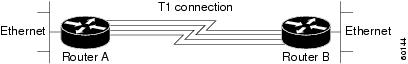
MLP provides characteristics are most similar to hardware inverse multiplexers, with good manageability and Layer 3 services support. Figure 1 shows a typical inverse multiplexing application using two Cisco routers and Multilink PPP over four T1 lines.
Figure 1 Inverse Multiplexing Application Using Multilink PPP
How to Configure Media-Independent PPP and Multilink PPP
This section includes the following procedures:
•
•
•
Configuring PPP and MLP
Perform the following task in interface configuration mode to configure PPP on a serial interface (including ISDN). This task is required for PPP encapsulation.
You can also complete the tasks in the following sections; these tasks are optional but offer a variety of uses and enhancements for PPP on your systems and networks:
•
•
•
•
•
•
See the "Monitoring and Maintaining PPP and MLP Interfaces" section for tips on maintaining PPP. See the "Configuration Examples for PPP and MLP" section to understand how to implement PPP and MLP in your network.
Enabling PPP Encapsulation
The encapsulation ppp command enables PPP on serial lines to encapsulate IP and other network protocol datagrams.
SUMMARY STEPS
1.
2.
3.
4.
5.
DETAILED STEPS
Enabling CHAP or PAP Authentication
To enable CHAP or PAP authentication, perform the steps mentioned in this section.
Caution
For an example of CHAP, see the section ""Examples: CHAP with an Encrypted Password:" section". CHAP is specified in RFC 1994, PPP Challenge Handshake Authentication Protocol (CHAP).
For information about MS-CHAP, see MS-CHAP Support.
SUMMARY STEPS
1.
2.
3.
4.
5.
or
aaa authentication ppp
6.
7.
8.
DETAILED STEPS
Configuring Compression of PPP Data
You can configure point-to-point software compression on serial interfaces that use PPP encapsulation. Compression reduces the size of a PPP frame via lossless data compression. PPP encapsulations support both predictor and Stacker compression algorithms.
If most of your traffic is already compressed files, do not use compression.
To configure compression of PPP data, perform the steps in this section.
Software Compression
Software compression is available on all router platforms. Software compression is performed by the main processor in the router.
Compression is performed in software and might significantly affect system performance. We recommend that you disable compression if the router CPU load exceeds 65 percent. To display the CPU load, use the show process cpu EXEC command.
SUMMARY STEPS
1.
2.
3.
4.
5.
6.
DETAILED STEPS
Configuring Microsoft Point-to-Point Compression
Perform this task to configure MPCC. This will help you set MPPC once PPP encapsulation is configured on the router.
Prerequisites
Ensure that PPP encapsulation is enabled before you configure MPPC. For information on how to configure PPP encapsulation, see the "Enabling PPP Encapsulation" section".
Restrictions
The following restrictions apply to the MPPC feature:
•
•
•
SUMMARY STEPS
1.
2.
3.
4.
DETAILED STEPS
Examples
Following is sample debug ppp negotiation command output showing protocol reject:
PPP Async2: protocol reject received for protocol = 0x2145PPP Async2: protocol reject received for protocol = 0x2145PPP Async2: protocol reject received for protocol = 0x2145Configuring IP Address Pooling
You can define the type of IP address pooling mechanism used on router interfaces in one or both of the ways described in the following sections:
•
•
Defining the Global Default Address Pooling Mechanism
The global default mechanism applies to all point-to-point interfaces that support PPP encapsulation and that have not otherwise been configured for IP address pooling. You can define the global default mechanism to be either DHCP or local address pooling.
To configure the global default mechanism for IP address pooling, perform the tasks in the following sections:
•
•
After you have defined a global default mechanism, you can disable it on a specific interface by configuring the interface for some other pooling mechanism. You can define a local pool other than the default pool for the interface or you can configure the interface with a specific IP address to be used for dial-in peers.
You can also control the DHCP network discovery mechanism; see the following section for more information:
•
Defining DHCP as the Global Default Mechanism
DHCP specifies the following components:
•
•
Perform this task to enable DHCP as the global default mechanism.
SUMMARY STEPS
1.
2.
3.
4.
5.
DETAILED STEPS
Defining Local Address Pooling as the Global Default Mechanism
Perform this task to define local address pooling as the global default mechanism.
Note
SUMMARY STEPS
1.
2.
3.
4.
DETAILED STEPS
Controlling DHCP Network Discovery
Perform the steps in this section to allow peer routers to dynamically discover Domain Name System (DNS) and NetBIOS name server information configured on a DHCP server using PPP IPCP extensions.
The ip dhcp-client network-discovery global configuration command provides a way to control the DHCP network discovery mechanism. The number of DHCP Inform or Discovery messages can be set to 1 or 2, which determines how many times the system sends the DHCP Inform or Discover messages before stopping network discovery. You can set a timeout period from 3 to 15 seconds, or leave the default timeout period at 15 seconds. The default for the informs and discovers keywords is 0, which disables the transmission of these messages.
SUMMARY STEPS
1.
2.
3.
DETAILED STEPS
Configuring IP Address Assignment
Perform this task to configure IP address allignment.
After you have defined a global default mechanism for assigning IP addresses to dial-in peers, you can configure the few interfaces for which it is important to have a nondefault configuration. You can do any of the following;
•
•
•
•
SUMMARY STEPS
1.
2.
3.
4.
5.
6.
7.
DETAILED STEPS
Troubleshooting PPP
You can troubleshoot PPP reliable link by using the debug lapb command and the debug ppp negotiations, debug ppp errors, and debug ppp packets commands. You can determine whether Link Access Procedure, Balanced (LAPB) has been established on a connection by using the show interface command.
Disabling or Reenabling Peer Neighbor Routes
The Cisco IOS software automatically creates neighbor routes by default; that is, it automatically sets up a route to the peer address on a point-to-point interface when the PPP IPCP negotiation is completed.
To disable this default behavior or to reenable it once it has been disabled, perform the following task:
SUMMARY STEPS
1.
2.
3.
4.
5.
DETAILED STEPS
Configuring Multilink PPP
The Multilink PPP feature provides load balancing functionality over multiple WAN links, while providing multivendor interoperability, packet fragmentation and proper sequencing, and load calculation on both inbound and outbound traffic. The Cisco implementation of MLP supports the fragmentation and packet sequencing specifications in RFC 1990. Additionally, you can change the default endpoint discriminator value that is supplied as part of user authentication. Refer to RFC 1990 for more information about the endpoint discriminator.
MLP allows packets to be fragmented and the fragments to be sent at the same time over multiple point-to-point links to the same remote address. The multiple links come up in response to a defined dialer load threshold. The load can be calculated on inbound traffic, outbound traffic, or on either, as needed for the traffic between the specific sites. MLP provides bandwidth on demand and reduces transmission latency across WAN links.
MLP is designed to work over synchronous and asynchronous serial and BRI and PRI types of single or multiple interfaces that have been configured to support both dial-on-demand rotary groups and PPP encapsulation.
Perform the tasks in the following sections, as required for your network, to configure MLP:
•
•
•
•
•
•
Configuring MLP on Synchronous Interfaces
To configure Multilink PPP on synchronous interfaces, you configure the synchronous interfaces to support PPP encapsulation and Multilink PPP.
Perform this task to configure a synchronous interface.
SUMMARY STEPS
1.
2.
3.
4.
5.
6.
7.
DETAILED STEPS
Configuring MLP on Asynchronous Interfaces
Perform the following steps in this section to configure an asynchronous interface to support DDR and PPP encapsulation and then configure a dialer interface to support PPP encapsulation, bandwidth on demand, and Multilink PPP.
At some point, adding more asynchronous interfaces does not improve performance, With the default maximum transmission unit (MTU) size, MLP should support three asynchronous interfaces using V.34 modems. However, packets might be dropped occasionally if the maximum transmission unit (MTU) size is small or large bursts of short frames occur.
Note
SUMMARY STEPS
1.
2.
3.
4.
5.
6.
7.
8.
DETAILED STEPS
Configuring MLP on a Single ISDN BRI Interface
To enable MLP on a single ISDN BRI interface, you are not required to define a dialer rotary group separately because ISDN interfaces are dialer rotary groups by default.
Perform this task to enable PPP on an ISDN BRI interface.
If you do not use PPP authentication procedures (Step 8), your telephone service must pass caller ID information.
The load threshold number is required. For an example of configuring MLP on a single ISDN BRI interface, see the "Example: MLP on One ISDN BRI Interface" section.
Note
SUMMARY STEPS
1.
2.
3.
4.
5.
6.
7.
8.
9.
10.
11.
DETAILED STEPS
Configuring MLP on Multiple ISDN BRI Interfaces
To enable MLP on multiple ISDN BRI interfaces, set up a dialer rotary interface and configure it for Multilink PPP, and then configure the BRI interfaces separately and add them to the same rotary group.
To set up the dialer rotary interface for the BRI interfaces, perform the following task:
SUMMARY STEPS
1.
2.
3.
4.
5.
6.
7.
8.
9.
10.
11.
12.
13.
DETAILED STEPS
If you do not use PPP authentication procedures (Step 10), your telephone service must pass caller ID information.
Repeat Steps 1 through 9 for each BRI that you want to belong to the same dialer rotary group.
When MLP is configured and you want a multilink bundle to be connected indefinitely, use the dialer idle-timeout command to set a very high idle timer. The dialer load-threshold 1 command does not keep a multilink bundle of n links connected indefinitely and the dialer load-threshold 2 command does not keep a multilink bundle of two links connected indefinitely.)
Note
For an example of configuring MLP on multiple ISDN BRI interfaces, see the section "Example: MLP on Multiple ISDN BRI Interfaces" section.
Configuring MLP Using Multilink Group Interfaces
MLP can be configured by assigning a multilink group to a virtual template configuration. Virtual templates allow a virtual access interface to dynamically clone interface parameters from the specified virtual template. If a multilink group is assigned to a virtual template, and then the virtual template is assigned to a physical interface, all links that pass through the physical interface will belong to the same multilink bundle.
Note
A multilink group interface configuration will override a global multilink virtual template configured with the multilink virtual template command.
Multilink group interfaces can be used with ATM, PPP over Frame Relay, and serial interfaces.
To configure MLP using a multilink group interface, perform the following tasks:
•
•
•
Perform the following tasks in this section to configure the multilink group. For an example of how to configure MLP over an ATM PVC using a multilink group, see the section "Example: MLP Using Multilink Group Interfaces over ATM" section.
SUMMARY STEPS
1.
2.
3.
4.
5.
6.
7.
8.
9.
10.
11.
12.
13.
DETAILED STEPS
Changing the Default Endpoint Discriminator
By default, when the system negotiates use of MLP with the peer, the value that is supplied for the endpoint discriminator is the same as the username used for authentication. That username is configured for the interface by the Cisco IOS ppp chap hostname or ppp pap sent-username command, or defaults to the globally configured hostname (or stack group name, if this interface is a Stack Group Bidding Protocol, or SGBP, group member).
Perform this task to override or change the default endpoint discriminator. For an example of how to change the default endpoint discriminator, see the "Example: Changing the Default Endpoint Discriminator" section.
SUMMARY STEPS
1.
2.
3.
4.
DETAILED STEPS
Configuring MLP Interleaving
Perform the following tasks to configure MLP and interleaving on a configured and operational interface or virtual interface template.
Configuring MLP Interleaving and Queueing
Interleaving on MLP allows large packets to be multilink encapsulated and fragmented into a small enough size to satisfy the delay requirements of real-time traffic; small real-time packets are not multilink encapsulated and are sent between fragments of the large packets. The interleaving feature also provides a special transmit queue for the smaller, delay-sensitive packets, enabling them to be sent earlier than other flows.
Weighted fair queueing on MLP works on the packet level, not at the level of multilink fragments. Thus, if a small real-time packet gets queued behind a larger best-effort packet and no special queue has been reserved for real-time packets, the small packet will be scheduled for transmission only after all the fragments of the larger packet are scheduled for transmission.
Weighted fair queueing is supported on all interfaces that support Multilink PPP, including MLP virtual access interfaces and virtual interface templates. Weighted fair queueing is enabled by default.
Fair queueing on MLP overcomes a prior restriction. Previously, fair queueing was not allowed on virtual access interfaces and virtual interface templates. Interleaving provides the delay bounds for delay-sensitive voice packets on a slow link that is used for other best-effort traffic.
Interleaving applies only to interfaces that can configure a multilink bundle interface. These restrictions include virtual templates, dialer interfaces, and ISDN BRI or PRI interfaces.
Multilink and fair queueing are not supported when a multilink bundle is off-loaded to a different system using Multichassis Multilink PPP (MMP). Thus, interleaving is not supported in MMP networking designs.
MLP support for interleaving can be configured on virtual templates, dialer interfaces, and ISDN BRI or PRI interfaces. To configure interleaving, complete the following tasks:
•
•
Note
Note
SUMMARY STEPS
1.
2.
3.
4.
5.
6.
7.
8.
9.
DETAILED STEPS
Configuring MLP Inverse Multiplexer and Distributed MLP
The distributed MLP (dMLP) feature combines T1/E1 lines in a WAN line card on a Cisco 7600 series router into a bundle that has the combined bandwidth of the multiple T1/E1 lines. You choose the number of bundles and the number of T1/E1 lines in each bundle, which allows you to increase the bandwidth of your network links beyond that of a single T1/E1 line without having to purchase a T3 line.
Nondistributed MLP is not supported on the Cisco 7600 series router. With distributed MLP, you can increase the router's total capacity.
The MLP Inverse Multiplexer feature was designed for Internet service providers (ISPs) that want to have the bandwidth of multiple T1 lines with performance comparable to that of an inverse multiplexer without the need of buying standalone inverse-multiplexing equipment. A Cisco router supporting dMLP can bundle multiple T1 lines in a CT3 or CE3 interface or channelized STM1. Bundling is more economical than purchasing an inverse multiplexer, and eliminates the need to configure another piece of equipment.
This feature supports the CT3 CE3 data rates without taxing the Route Processor (RP) and CPU by moving the data path to the line card. This feature also allows remote sites to purchase multiple T1 lines instead of a T3 line, which is especially useful when the remote site does not need the bandwidth of an entire T3 line.
This feature allows multilink fragmentation to be disabled, so multilink packets are sent using Cisco Express Forwarding on all platforms, if fragmentation is disabled. Cisco Express Forwarding is supported with fragmentation enabled or disabled.
Note
If there is no service policy on the dMLP interface, when a ppp multilink interleave is configured on the dMLPPP interface, a QoS policy is enabled internally.
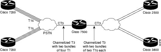
Figure 2 shows a typical network using a dMLP link. The Cisco 7600 series router is connected to the network with a CT3 line that has been configured with dMLPP to carry two bundles of four T1 lines each. One of these bundles goes out to a Cisco 2500 series router and the other goes out to a Cisco 3800 series router.
Figure 2 Diagram of a Typical VIP MLP Topology
Before beginning the MLP Inverse Multiplexer configuration tasks, make note of the following prerequisites and restrictions.
Prerequisites
•
•
–
–
–
–
–
–
–
•
Restrictions
The following restrictions apply to the dMLP feature:
Note
•
•
•
•
•
•
•
•
•
•
•
•
•
Enabling fragmentation reduces the delay latency among bundle links, but adds some load to the CPU. Disabling fragmentation may result in better throughput.
If your data traffic is consistently of a similar size, we recommend disabling fragmentation. In this case, the benefits of fragmentation may be outweighed by the added load on the CPU.
To configure a multilink bundle, perform the tasks in the following sections:
•
•
•
Creating a Multilink Bundle
Perform the following tasks to create a multilink bundle.
SUMMARY STEPS
1.
2.
3.
4.
5.
6.
DETAILED STEPS
Assigning an Interface to a Multilink Bundle
Perform this task to assign an interface to a multilink bundle.
SUMMARY STEPS
1.
2.
3.
4.
5.
6.
7.
8.
9.
10.
DETAILED STEPS
Caution
Disabling PPP Multilink Fragmentation
Perform the following task to disable PPP multilink fragmentation.
SUMMARY STEPS
1.
2.
3.
4.
5.
DETAILED STEPS
Monitoring and Maintaining PPP and MLP Interfaces
Perform this task to display MLP and MMP bundle information.
SUMMARY STEPS
1.
2.
3.
DETAILED STEPS
Configuration Examples for PPP and MLP
The following sections provide various PPP configuration examples:
•
•
•
•
•
•
•
•
Examples: CHAP with an Encrypted Password:
The following examples show how to enable CHAP on serial interface 0 of three devices:
Configuration of Device yyy
hostname yyyinterface serial 0encapsulation pppppp authentication chapusername xxx password secretxyusername zzz password secretzyConfiguration of Device xxx
hostname xxxinterface serial 0encapsulation pppppp authentication chapusername yyy password secretxyusername zzz password secretxzConfiguration of Device zzz
hostname zzzinterface serial 0encapsulation pppppp authentication chapusername xxx password secretxzusername yyy password secretzyWhen you look at the configuration file, the passwords are encrypted and the display looks similar to the following:
hostname xxxinterface serial 0encapsulation pppppp authentication chapusername yyy password 7 121F0A18username zzz password 7 1329A055Example: Changing the Default Endpoint Discriminator
The following partial example changes the MLP endpoint discriminator from the default CHAP hostname C-host1 to the E.164-compliant telephone number 555-0100:
...interface dialer 0ip address 10.1.1.4 255.255.255.0encapsulation pppdialer remote-name R-host1dialer string 23456dialer pool 1dialer-group 1ppp chap hostname C-host1ppp multilink endpoint phone 555-0100...Example: DHCP Network Control
The following partial example shows how to add the ip dhcp-client network-discovery command to the "Example: IP Address Pooling" section to allow peer routers to more dynamically discover DNS and NetBIOS name servers. If the ip dhcp-client network-discovery command is disabled, the system falls back to the static configurations made using the async-bootp dns-server and async-bootp nb-server global configuration commands.
!hostname secret!aaa new-modelaaa authentication login default localaaa authentication ppp default if-needed localaaa authentication ppp chap localenable secret 5 encrypted-secretenable password EPassWd1!username User1 password 0 PassWd2username User2 password 0 PassWd3username User3 password 0 PassWd4no ip domain-lookupip dhcp-server 10.47.0.131ip dhcp-client network-discovery informs 2 discovers 2 period 12async-bootp gateway 10.47.0.1async-bootp nbns-server 10.47.0.131isdn switch-type primary-4ess...Example: IP Address Pooling
The following example shows how to configure a modem to dial in to a Cisco access server and obtain an IP address from the DHCP server. This configuration allows the user to log in and browse an NT network. Notice that the dialer 1 and group-async 1 interfaces are configured with the ip unnumbered loopback command, so that the broadcast can find the dialup clients and the client can see the NT network.
!hostnamesecret!aaa new-modelaaa authentication login default localaaa authentication ppp default if-needed localaaa authentication ppp chap localenable secret 5encrypted-secretenable passwordEPassWd1Example: MPPC Interface Configuration
The following example shows how to configure asynchronous interface 1 to implement MPPC and ignore the protocol field compression flag negotiated by LCP:
interface async1ip unnumbered ethernet0encapsulation pppasync default routingasync dynamic routingasync mode interactivepeer default ip address 172.21.71.74compress mppc ignore-pfcThe following example creates a virtual access interface (virtual template interface 1) and serial interface 0, which is configured for X.25 encapsulation. MPPC values are configured on the virtual template interface and will ignore the negotiated protocol field compression flag.
interface ethernet0ip address 172.20.30.102 255.255.255.0!interface virtual-template1ip unnumbered ethernet0peer default ip address pool vtemp1compress mppc ignore-pfc!interface serial0no ipaddressno ip mroute-cacheencapsulation x25x25 win 7x25 winout 7x25 ips 512x25 ops 512clock rate 50000!ip local pool vtemp1 172.20.30.103 172.20.30.104ip route 0.0.0.0 0.0.0.0 172.20.30.1!translate x25 31320000000000 virtual-template 1Examples: MLP
This section contains the following MLP examples:
•
•
•
•
•
•
Example: MLP on Synchronous Serial Interfaces
The following example shows how the configuration commands are used to create the inverse multiplexing application:
Device A Configuration
hostname DeviceA!!username DeviceB password your_passwordip subnet-zeromultilink virtual-template 1!interface Virtual-Template1ip unnumbered Ethernet0ppp authentication chapppp multilink!interface Serial0no ip addressencapsulation pppno fair-queueppp multilinkpulse-time 3!interface Serial1no ip addressencapsulation pppno fair-queueppp multilinkpulse-time 3!interface Serial2no ip addressencapsulation pppno fair-queueppp multilinkpulse-time 3!interface Serial3no ip addressencapsulation pppno fair-queueppp multilinkpulse-time 3!interface Ethernet0ip address 10.17.1.254 255.255.255.0!router ripnetwork 10.0.0.0!endDevice B Configuration
hostname DeviceB!!username DeviceB password your_passwordip subnet-zeromultilink virtual-template 1!interface Virtual-Template1ip unnumbered Ethernet0ppp authentication chapppp multilink!interface Serial0no ip addressencapsulation pppno fair-queueppp multilinkpulse-time 3!interface Serial1no ip addressencapsulation pppno fair-queueppp multilinkpulse-time 3!interface Serial2no ip addressencapsulation pppno fair-queueppp multilinkpulse-time 3!interface Serial3no ip addressencapsulation pppno fair-queueppp multilinkpulse-time 3!interface Ethernet0ip address 10.17.2.254 255.255.255.0!router ripnetwork 10.0.0.0!endExample: MLP on One ISDN BRI Interface
The following example shows how to enable MLP on BRI interface 0. When a BRI is configured, no dialer rotary group configuration is required, because an ISDN interface is a rotary group by default.
interface bri 0description connected to ntt 81012345678902ip address 172.31.1.7 255.255.255.0encapsulation pppdialer idle-timeout 30dialer load-threshold 40 eitherdialer map ip 172.31.1.8 name user1 81012345678901dialer-group 1ppp authentication papppp multilinkExample: MLP on Multiple ISDN BRI Interfaces
The following example shows how to configure multiple ISDN BRI interfaces to belong to the same dialer rotary group for Multilink PPP. The dialer rotary-group command is used to assign each of the ISDN BRI interfaces to that dialer rotary group.
interface BRI 0no ip addressencapsulation pppdialer idle-timeout 500dialer rotary-group 0dialer load-threshold 30 either!interface BRI 1no ip addressencapsulation pppdialer idle-timeout 500dialer rotary-group 0dialer load-threshold 30 either!interface BRI 2no ip addressencapsulation pppdialer idle-timeout 500dialer rotary-group 0dialer load-threshold 30 either!interface Dialer 0ip address 10.0.0.2 255.0.0.0encapsulation pppdialer in-banddialer idle-timeout 500dialer map ip 10.0.0.1 name user1 broadcast 81012345678901dialer load-threshold 30 eitherdialer-group 1ppp authentication chapppp multilinkExample: MLP Using Multilink Group Interfaces over ATM
The following example shows how to configure MLP over an ATM PVC using a multilink group:
interface multilink 1ip address 10.200.83.106 255.255.255.252ip tcp header-compression iphc-format delay 20000service policy output xyzencapsulation pppexitppp multilinkppp multilink fragment delay 10ppp multilink interleaveppp timeout multilink link remove 10ip rtp header-compression iphc-formatinterface virtual-template 3bandwidth 128ppp multilink group 1interface atm 4/0.1 point-to-pointpvc 0/32abr 100 80protocol ppp virtual-template 3Example: MLP Inverse Multiplexer Configuration
This example shows how to verify the display information of the newly created multilink bundle:
Device# show ppp multilinkMultilink1, bundle name is group1Bundle is Distributed0 lost fragments, 0 reordered, 0 unassigned, sequence 0x0/0x0 rcvd/sent0 discarded, 0 lost received, 1/255 loadMember links:4 active, 0 inactive (max not set, min not set)Serial1/0/0:1Serial1/0/0/:2Serial1/0/0/:3Serial1/0/0/:4Example: MLP Interleaving and Queueing for Real-Time Traffic
The following example defines a virtual interface template that enables MLP interleaving and a maximum real-time traffic delay of 20 milliseconds, and then applies that virtual template to the MLP bundle:
interface virtual-template 1ip unnumbered ethernet 0ppp multilinkppp multilink interleaveppp multilink fragment delay 20ip rtp interleave 32768 20 1000multilink virtual-template 1The following example enables MLP interleaving on a dialer interface that controls a rotary group of BRI interfaces. This configuration permits IP packets to trigger calls.
interface BRI 0description connected into a rotary groupencapsulation pppdialer rotary-group 1!interface BRI 1no ip addressencapsulation pppdialer rotary-group 1!interface BRI 2encapsulation pppdialer rotary-group 1!interface BRI 3no ip addressencapsulation pppdialer rotary-group 1!interface BRI 4encapsulation pppdialer rotary-group 1!interface Dialer 0description Dialer group controlling the BRIsip address 10.1.1.1 255.255.255.0encapsulation pppdialer map ip 10.1.1.2 name name1 14802616900dialer-group 1ppp authentication chap! Enables Multilink PPP interleaving on the dialer interface and reserves! a special queue.ppp multilinkppp multilink interleaveip rtp reserve 32768 20 1000! Keeps fragments of large packets small enough to ensure delay of 20 ms or less.ppp multilink fragment delay 20dialer-list 1 protocol ip permitExample: Multilink Interface Configuration for Distributed MLP
In the following example, four multilink interfaces are created with distributed Cisco Express Forwarding switching and MLP enabled. Each of the newly created interfaces is added to a multilink bundle.
interface multilink1ip address 10.0.0.0 10.255.255.255ppp chap hosstname group 1ppp multilinkppp multilink group 1interface serial 1/0/0:1no ip addressencapsulation pppip route-cache distributedno keepaliveppp multilinkppp multilink group 1interface serial 1/0/0:2no ip addressencapsulation pppip route-cache distributedno keepaliveppp chap hostname group 1ppp multilinkppp multilink group 1interface serial 1/0/0:3no ip addressencapsulation pppip route-cache distributedno keepaliveppp chap hostname group 1ppp multilinkppp multilink group 1interface serial 1/0/0:4no ip addressencapsulation pppip route-cache distributedno keepaliveppp chap hostname group 1ppp multilinkppp multilink group 1Example: PAP commands for a one way authentication
The following example shows how to authenticate PAP commands for a one way authentication scenario:
Note
Calling Side (Client) Configurationinterface BRI0! --- BRI interface for the dialout.ip address negotiatedencapsulation ppp! --- Use PPP encapsulation. This command is a required for PAP.dialer string 3785555 class 56k! --- Number to dial for the outgoing connection.dialer-group 1isdn switch-type basic-niisdn spid1 51299611110101 9961111isdn spid2 51299622220101 9962222ppp authentication pap callin! --- Use PAP authentication for incoming calls.! --- The callin keyword has made this a one-way authentication scenario.! --- This router (client) will not request that the peer (server) authenticate! --- itself back to the client.ppp pap sent-username PAPUSER password 7 <deleted>! --- Permit outbound authentication of this router (client) to the peer.! --- Send a PAP AUTH-REQ packet to the peer with the username PAPUSER and password.! --- The peer must have the username PAPUSER and password configured on it.Receiving Side (Server) Configurationusername PAPUSER password 0 cisco! --- Username PAPUSER is the same as the one sent by the client.! --- Upon receiving the AUTH-REQ packet from the client, we will verify that the! --- username and password match the one configured here.interface Serial0:23! --- This is the D-channel for the PRI on the access server receiving the call.ip unnumbered Ethernet0no ip directed-broadcastencapsulation ppp! --- Use PPP encapsulation. This command is a required for PAP.dialer-group 1isdn switch-type primary-niisdn incoming-voice modempeer default ip address pool defaultfair-queue 64 256 0ppp authentication pap! --- Use PAP authentication for incoming calls.! --- This router (server) will request that the peer authenticate itself to us.! --- Note: the callin option is not used as this router is not initiating the call.Example: T3 Controller Configuration for an MLP Multilink Inverse Multiplexer
The following example shows how to configure the T3 controller and create four channelized interfaces:
controller T3 1/0/0framing m23cablelength 10t1 1 timeslots 1-24t1 2 timeslots 1-24t1 3 timeslots 1-24t1 4 timeslots 1-24Example: User Maximum Links Configuration
The following example shows how to configure the username user1 and establish a maximum of five connections. user1 can connect through serial interface 1/0, which has a dialer map configured for it, or through PRI interface 0/0:23, which has dialer profile interface 0 dedicated to it.
The aaa authorization network default local command must be configured. PPP encapsulation and authentication must be enabled on all the interfaces that user1 can connect to.
aaa new-modelaaa authorization network default localenable secret password1enable password password2!username user1 user-maxlinks 5 password password3!interface Serial0/0:23no ip addressencapsulation pppdialer pool-member 1ppp authentication chapppp multilink!interface Serial1/0ip address 209.165.201.1 255.255.255.0encapsulation pppdialer in-banddialer map ip 10.2.2.13 name user1 12345dialer-group 1ppp authentication chap!interface Dialer0ip address 209.165.200.225 255.255.255.0encapsulation pppdialer remote-name user1dialer string 23456dialer pool 1dialer-group 1ppp authentication chapppp multilink!dialer-list 1 protocol ip permitAdditional References
The following sections provide references related to the Configuring Media-Independent PPP and Multilink PPP feature.
Related Documents
Asynchronous SLIP and PPP
"Configuring Asynchronous SLIP and PPP" module in the Cisco IOS Dial Technologies Configuration Guide
MCHAP
Dial commands: complete command syntax, command mode, command history, defaults, usage guidelines, and examples
RFCs
Technical Assistance
Feature Information for Configuring Media-Independent PPP and Multilink PPP
Table 1 lists the release history for this feature.
Not all commands may be available in your Cisco IOS software release. For release information about a specific command, see the command reference documentation.
Use Cisco Feature Navigator to find information about platform support and software image support. Cisco Feature Navigator enables you to determine which Cisco IOS and Catalyst OS software images support a specific software release, feature set, or platform. To access Cisco Feature Navigator, go to http://www.cisco.com/go/cfn. An account on Cisco.com is not required.
Note
Table 1 Feature Information for Configuring Media-Independent PPP and Multilink PPP
Multilink PPP
11.2(1)
12.2(8)T
11.2(6)P
12.1(3)T
12.3(13)BC
12.2(27)SBB
12.2(31)SB2
15.0(1)M
12.2(33)SRE
15.2(2)SMultilink PPP provides a method for spreading traffic across multiple physical WAN links.
The following sections provide information about this feature:
•
•
The following commands were introduced or modified:
ppp multilink, ppp multilink group.
Cisco and the Cisco logo are trademarks or registered trademarks of Cisco and/or its affiliates in the U.S. and other countries. To view a list of Cisco trademarks, go to this URL: www.cisco.com/go/trademarks. Third-party trademarks mentioned are the property of their respective owners. The use of the word partner does not imply a partnership relationship between Cisco and any other company. (1110R)
Any Internet Protocol (IP) addresses and phone numbers used in this document are not intended to be actual addresses and phone numbers. Any examples, command display output, network topology diagrams, and other figures included in the document are shown for illustrative purposes only. Any use of actual IP addresses or phone numbers in illustrative content is unintentional and coincidental.
© 2001-2012 Cisco Systems, Inc. All rights reserved.