Cisco ASR 1002-F Router Description
The Cisco ASR 1002-F Router is one of the Cisco ASR 1000 Series Aggregation Services Routers. The Cisco ASR 1002-F Router supports all the general-purpose routing and security features of the Cisco ASR 1002 Router, and uses the same internal control and data-plane architecture as Cisco ASR 1002 Router.
The Cisco ASR 1002-F Router supports:
-
The same features and components as the Cisco ASR 1002 Router
-
An integrated 4xGE SPA interface
-
Fixed 2.5 GB of system bandwidth and 4 GB DRAM
-
A built-in 4x1GE SPA providing four small form-factor pluggable (SFP-based) GE connections, designated as SPA bay 0
.
For information about the SFP transceiver modules that are compatible with Cisco ASR 1002 Built-in Gigabit Ethernet Ports (4x1GE), refer to the “Modular Optics Compatibility” section in Cisco ASR 1000 Series Aggregation Services Routers SIP and SPA Hardware Installation Guide .
 Note |
Only Cisco software release four code supports the Cisco ASR 1002-F Router. Do not use earlier versions of Cisco software. |
This section contains the following topics:
Front View
Cisco ASR 1002-F Router—Front View shows the front of the Cisco ASR 1002-F Router with the Cisco ASR 1002-ESP-F, Cisco ASR 1000 route processor, and a SPA-4XOC12-POS installed.

|
1 |
Integrated Cisco ASR 1002-ESP-F |
3 |
Cisco ASR 1002-SIP10-F with a SPA installed |
|
2 |
Integrated Cisco RP |
— |
— |
Rear View
The following image shows the rear of the Cisco ASR 1002-F Router with AC power supplies installed.
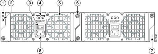
|
1 |
Chassis ESD socket |
5 |
Fan |
|
2 |
AC power supply slot 0 label |
6 |
Captive installation screw |
|
3 |
AC power supply On (|)/Off (O) switch |
7 |
AC power supply slot 1 label |
|
4 |
AC power supply LEDs |
8 |
AC power inlet |
 Note |
On the side of the Cisco ASR 1002-F Router there is an eUSB panel door and the grounding lug as shown in the “Cisco ASR 1002-F Router Chassis Ground Lug Location and eUSB Side Panel Door” figure in the Attaching a Chassis Ground Connection section. This panel door must not be opened. There is a Do Not Tamper label on the panel door. Do not remove the label. If there is a problem with the eUSB flash card, then the chassis should be returned. |
The follwing image shows the rear of the Cisco ASR 1002-F Router with DC power supplies installed.
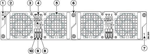
|
1 |
Chassis ESD socket |
6 |
Captive installation screw |
|
2 |
DC power supply slot 0 label |
7 |
DC power supply slot 1 label |
|
3 |
DC power supply Standby/On (|) switch |
8 |
Ground lead |
|
4 |
DC power supply LEDs |
9 |
Positive lead |
|
5 |
Fan |
10 |
Negative lead |
Internal fans draw cooling air into the chassis and across internal components to maintain an acceptable operating temperature. The fans are located at the rear of the chassis. A two-hole ground connector lug is located on the side of the chassis. Two power supplies, either two AC power supplies or two DC power supplies, are accessed from the rear of the router.
 Caution |
Use only AC power supplies or DC power supplies in the Cisco ASR 1002-F Router. Do not mix power supply types. |
Cisco ASR 1002-F Router Slot Numbering
The Cisco ASR 1002-F Router contains:
-
One Cisco integrated RP— R0
-
One integrated Cisco ASR1000-ESP-F forwarding processor— F0
-
One integrated ASR1002-SIP10-F—slot 0
-
4-Gigabit Ethernet built-in interface—slot 0/0
-
SPA-5x1GE-V2—slot 0/1
The following figure shows the slot numbering for the Cisco ASR 1002-F Router.

|
1 |
Slot 0 |
3 |
Slot 2 |
|
2 |
Slot 1 |
— |
— |








 Feedback