Cisco ASR 1013 Router Description
 Note |
ASR1000-MIP100 is supported only in slot 2 and 3 of Cisco ASR 1013 |
The Cisco ASR 1013 Router supports full-width card modules. It is designed with a single midplane with connectors on one interface midplane. The Cisco ASR 1013 Router supports:
-
Up to 6 ASR1000-SIP40G shared port adapter modules
-
Up to 24 shared port adapters (SPAs) and up to six SIPs
-
Two embedded services processors (Cisco ASR1000-ESP40, Cisco ASR1000-ESP100, or Cisco ASR1000-ESP200)
-
Cisco ASR1000-RP2 route processor
-
Quad power supplies (redundant pairs) by default; option of either AC or DC power supplies and two power supply zones. There are two power supplies for power zone 0 and two power supplies for power zone 1 (do not mix AC and DC power supplies).
 Note |
You must have one power supply running at all times from each power supply zone and two power supplies from each power supply zone to support redundancy. For detailed power supply information about the Cisco ASR 1013 Router, see the Connecting Power to the Cisco ASR 1013 Router. |
Front View
The following image shows the Cisco ASR 1013 Router with modules and filler plates installed.

|
1 |
ASR 1000 Series SIP slot 0 |
6 |
ASR 1000 Series SIP slot 5 |
|
2 |
ASR 1000 Series SIP slot 1 |
R0 |
Slot R0 with ASR 1000- RP2 |
|
3 |
ASR 1000 Series SIP slot 2 |
F0 |
Slot F0 with Cisco ASR 1000-ESP40, Cisco ASR 1000-ESP100, or Cisco ASR 1000-ESP200 |
|
4 |
ASR 1000 Series SIP slot 3 |
F1 |
Slot F1 with Cisco ASR 1000-ESP40, Cisco ASR 1000-ESP100, or Cisco ASR 1000-ESP200 |
|
5 |
ASR 1000 Series SIP slot 4 |
R1 |
Slot R1 with ASR 1000-RP2 |
| Note: Slots 10, 9, 8, 7, and 6 reside in power zone 0 and slots 5, 4, 3, 2, and 1 reside in power zone 1. |
Rear View
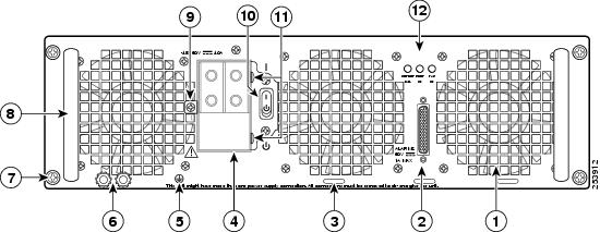
The following image shows the rear of the Cisco ASR 1013 Router with the AC power supplies installed.

|
1 |
Cable-management brackets |
6 |
AC power supply in slot 2 (power supply zone 1) |
|
2 |
Forward rack-mount ears are shipped installed |
7 |
AC power supply in slot 1 (power supply zone 0) |
|
3 |
Chassis handle |
8 |
AC power supply in slot 0 (power supply zone 0) |
|
4 |
Rear rack-mount brackets |
9 |
Chassis ground stud |
|
5 |
AC power supply in slot 3 (power supply zone 1) |
— |
— |
Cisco ASR 1013 Router Power Zones
Internal fans draw cooling air into the chassis and across internal components to maintain an acceptable operating temperature. (See the preceding figure.) The fans are built into the power supply allowing fan and power supply replacement. A two-hole grounding lug is located on the bottom rear of the chassis (see the preceding figure, callout 6). Four power supplies, either AC power supplies or DC power supplies, are accessed from the rear of the router. The power supply bays are numbered from bottom to top: 0, 1, 2, and 3 respectively.
The Cisco ASR 1013 Router has two power zones:
-
Power zone 1(top half of chassis) includes slots:
-
PS1-A
-
PS1-B
-
Carrier card slots 3, 4, and 5
-
RP1
- FP1
-
-
Power zone 0 (bottom half of chassis) includes slots:
-
PS0-A
-
PS0-B
-
Carrier card slots 0, 1, and 2
-
RP0
- FP0
-
 Note |
Do not combine AC and DC power supplies in the same chassis. |
 Note |
Cisco ASR 1013 Router supports only Cisco ASR1000-RP2. |
 Warning |
This warning symbol means danger. You are in a situation that could cause bodily injury. Before you work on any equipment, be aware of the hazards involved with electrical circuitry and be familiar with standard practices for preventing accidents. Use the statement number provided at the end of each warning to locate its translation in the translated safety warnings that accompanied this device. Statement 1071 |
 Warning |
Before you install, operate, or service the system, read the Regulatory Compliance and Safety Information for Cisco ASR 1000 Series Aggregation Services Routers publication. This document provides important safety information you should know before working with the system. Statement 200 |
 Note |
You have already unpacked your chassis and read all the site requirements for your new equipment. Proceed with the installation. |
Cisco ASR 1013 Router Slot Numbering
The Cisco ASR 1013 chassis has two Cisco ASR100-RP2 (R0, R1) slots, two embedded services processor slots (F0, F1) and six dedicated Cisco ASR1000-SIP slots (from bottom of chassis up, 0, 1, 2, 3, 4, 5 respectively).
The Cisco ASR 1013 Router is designed with each slot numbered as shown in the “Cisco ASR 1013 Router—Rear View” figure in the Rear View section.
 Note |
Cisco ASR 1013 slots are keyed using rotated guide pins for the plug-in card to be fully inserted in slots where they are intended to operate. This keyed feature prevents cards from being inserted into the wrong slots. |
The Cisco ASR 1013 Router contains six SPA Interface Processor (SIPs) slots and supports four subslots for the installation of SPAs. The following shows the Cisco ASR 1013 Router SPA subslot location.





 Feedback