Cisco ASR 1000 Series Routers Component Overview

This chapter contains the following sections:


Note

For the Cisco Embedded Services Processor see, xref and for the SPA Interface Processor see, xref

Cisco ASR 1000 Series Routers Component Software Support

This section lists the new hardware supported on the Cisco ASR 1000 Series routers and the version of Cisco IOS software code required to support the component. xref table lists the components that are not supported by earlier releases of Cisco IOS XE.

Upgrading to New Software


Note

For a listing of the new SPAs, click the corresponding link in the table.
Table 1. Cisco ASR 1000 Series Router Component Software Support

Cisco IOS XE Software Support

Cisco Hardware Components

Cisco IOS XE Release 2.1.0

  • Cisco ASR 1002 Router

  • Cisco ASR 1004 Router

  • Cisco ASR 1006 Router

  • Cisco ASR 1000 Embedded Services Processors

  • Cisco ASR 1000 Route Processor 1

  • Cisco ASR 1000 SPA Interface Processor

  • Shared Port Adapters

  • 1 GB USB Flash Token for Cisco ASR 1000 Series

Cisco IOS XE Release 2.2.1

  • Cisco ASR 1000 Embedded Services Processor 10G Non Crypto Capable (ASR1000-ESP10-N)

  • Cisco ASR1000-ESP20 embedded services processor

  • Shared Port Adapters

Cisco IOS XE Release 2.3.0

  • Cisco ASR 1000 Series Route Processor 2 (Cisco ASR1000-RP2)

  • Shared Port Adapters

Cisco IOS XE Release 2.4.0

  • Cisco ASR 1002-F Router

  • WebEx SPA

Cisco IOS XE Release 2.5.0

  • 1-Port Clear Channel OC-12 ATM SPA (SPA-1XOC12-ATM-v2)

  • New XFP/SFPs Supported with SPAs and the Built-In Gigabit Ethernet Interface

Cisco IOS XE Release 2.6.0

1-Port Channelized OC-12/STM-4 SPA (SPA-1XCHOC12/DS0)

Cisco IOS XE 3.1S (formerly Release 2.7.0)

  • Chapter 11, “Cisco ASR 1013 Router Overview and Installation”

  • Chapter 3, “Cisco ASR 1000 Series Routers Embedded Services Processors”

  • Chapter 4, “Cisco ASR 1000 Series Router SPA Interface Processors (SIPs)”

Cisco IOS XE 3.2S (formerly Release 2.8.0)

  • Chapter 12, “Cisco ASR 1001 Router Overview and Installation”

  • Cisco ASR1000-ESP40 and Cisco ASR1000-SIP40 support on Cisco ASR 1004 Router

Cisco IOS XE 3.7S

  • Chapter 10, “Cisco ASR 1002-X Router Overview and Installation”

  • Cisco ASR1000-ESP100 support on Cisco ASR 1006 Router and Cisco ASR 1013 Router

Supported ASR 1000 Hardware Components

This section contains the following topics:

Supported Cisco ASR 1000 Platforms

The following table lists the Cisco ASR 1000 Series Routers and the hardware components supported in each router.

Table 2. Supported Cisco ASR 1000 Platforms and Components

Component

ASR 1001

ASR 1002-F

ASR 1002

ASR 1002-X

ASR 1004

ASR 1006

ASR 1013

Chassis

Scalable to 5 Gbps

Scalable to 2.5 Gbps

Scalable to 10 Gbps

Scalable to 36 Gbps

Scalable to 40 Gbps

Scalable to 100 Gbps

Scalable to 100 Gbps

Supports software redundancy

Supports software redundancy

Supports software redundancy

Supports software redundancy

Supports hardware redundancy

Supports hardware redundancy

One built-in 4x1 Gigabit Ethernet SPA

Four built-in Gigabit Ethernet ports

Four built-in Gigabit Ethernet ports

Six built-in Gigabit Ethernet ports

ESP

Single integrated ASR1000-ESP2.5

Single integrated ASR1000-ESP2.5

Single ASR1000-ESP5

Single integrated embedded services processor

Single ASR1000-ESP10

Single or Dual ASR1000-ESP10

Single ASR1000-ESP10

Single ASR1000-ESP20

Single or Dual ASR1000-ESP20

ASR1000-ESP40

Single or Dual ASR1000-ESP40

Single or Dual ASR1000-ESP40

Single or Dual ASR1000-ESP100

Single or Dual ASR1000-ESP100

2.5 up to 5 Gbps

5 or 10 Gbps

5 Gbps, 10 Gbps, 20 Gbps, or 36 Gbps, depending on the Cisco software license installed

10 or 20 Gbps

10, 20, 40, or 100 Gbps

40 or 100 Gbps

Route Processor

Single integrated route processor

Single integrated ASR1000-RP1

Single integrated ASR1000-RP1

Single integrated route processor

Single ASR1000-RP1

Single or Dual ASR1000-RP1

Single ASR1000-RP2

Single or Dual ASR1000-RP2

Single or Dual ASR1000-RP2

SIP

Integrated SIP

Integrated SIP

Integrated SIP

Integrated SIP

ASR1000-SIP10

ASR1000-SIP10

ASR1000-SIP10

ASR1000-SIP40

ASR1000-SIP40

ASR1000-SIP40

SPA Slots

1 half-height (HH) SPA bay

1

3

3 HH SPA bays

8

12

24

Cisco ASR 1000 Series Hardware Configuration Combinations

This section provides Cisco ASR 1000 Series hardware configuration combinations and whether they are supported from Cisco IOS XE Release 3.1S onward. The tables list the router and the route processor, SIPs, and power modules supported on that router. The tables include the following categories

  • Supported hardware before IOS XE Release 3.1S—xref table
  • Supported hardware from IOS XE Release 3.1S—xref table
  • Requires upgrade—xref table
  • Not compatible—xref table
  • Not supported in IOS XE Release 3.1S—xref table
  • Incompatible HA—xref table

Note

When an unsupported combination of hardware components occurs, the card or cards not supported are shutdown and an error message occurs. Following each table in this section, a description of the error message is provided.To prevent any errors from occurring, read the compatibility tables before you insert any Cisco ASR 1000 Series Router components on a router running Cisco IOS XE Release 3.1S or later releases.

Incompatible Hardware Configuration Combinations

The following table lists ASR 1000 hardware configuration combinations that are not compatible from Cisco IOS XE Release 3.1S onward.

Table 3. Incompatible Cisco Hardware Configuration Combinations from IOS XE Release 3.1S Onward

Chassis

ASR1000-RP

ASR1000-ESP

ASR1000-SIP

Result

Cisco ASR 1002 Router

NA (built in)

ESP-20

ESP-40

ESP-100

NA (built in)

ESP-20 disabled

ESP-40 disabled

ESP-100 disabled

Cisco ASR 1004 Router

ESP-5

ESP-100

ESP-5 disabled

ESP-100 disabled

Cisco ASR 1006 Router

ESP-5

ESP-5 disabled

Cisco ASR 1013 Router

RP1

RP1 disabled

Cisco ASR 1001 Router

NA (built in)

Integrated embedded services processor

NA (built in)

Cisco ASR 1002-X Router

NA (built in)

Integrated embedded services processor

NA (built in)

Incompatible ASR1000-ESP Error Message

This section describes what happens when an incompatible Cisco ASR1000-ESP is inserted into the following Cisco ASR 1000 series router:

  • Cisco ASR1000-ESP20 is inserted into Cisco ASR 1002 Router
  • Cisco ASR1000-ESP40 is inserted into Cisco ASR 1002 Router
  • Cisco ASR1000-ESP100 is inserted into Cisco ASR 1002 Router
  • Cisco ASR1000-ESP5 or Cisco ASR1000-ESP100 is inserted into Cisco ASR 1004 Router or ASR 1006 Router
Error message

The Cisco ASR1000-ESP card is disabled, and the following error message is displayed on the console:


Error message: %CMRP-3-INCOMPATIBLE_FRU: [chars] in slot [chars] is not compatible with [chars] and so it is disabled.
fp_name: ESP-5/ESP-20/ESP-40/ESP-100
fp_slot: F0/F1
hw_config: ASR-1002/ASR-1004/ASR-1006 chassis
Reason

The Product ID read from the FRU IDPROM is not compatible with this hardware configuration.

Recommended action

Remove the embedded services processor from the chassis.

Incompatible ASR1000-RP Error Message

This section describes what happens when a Cisco ASR1000-RP1 is inserted into the Cisco ASR 1013 router and provides the error message and explanation as to why this occurred:

Error message

The ASR1000-RP1 is disabled and the following error message displays at the console.


Error message: %CMRP-3-INCOMPATIBLE_FRU: [chars] in slot [chars] is not compatible with [chars] and so it is disabled”
rp_name: RP1
rp_slot: R0/R1
hw_config: ASR-1013 chassis
Reason

The Product ID read from the FRU IDPROM is not supported in this hardware configuration.

Recommended action

Remove the Cisco ASR1000-RP1 from the chassis.

Unsupported Hardware Configurations

The following table lists Cisco ASR 1000 Series Routers hardware configurations that are not supported.

Table 4. Cisco ASR 1000 Series Routers Hardware Configurations That Are Not Supported

Router

ASR1000-RP

ASR1000-ESP

ASR1000-SIP

Result

Cisco ASR 1004 Router

ESP-40

ESP-100

ESP-100 disabled

Cisco ASR 1006 Router

RP1

ESP-40

ESP-40 disabled

Cisco ASR 1001 Router

Integrated embedded services processor

SIP-40 disabled

The following may be the outcome when using unsupported Cisco ASR 1000 components in a high-availability feature configuration:

  • Unsupported ASR1000-RP in a redundant Cisco ASR 1006 configuration—If you insert an Cisco ASR1000-RP1 or RP2 in an ASR 1006 redundant setup, the following occurs:

The standby ASR1000-RP card is disabled and this error message prints on the active RP console:


Error message: %CMRP-3-RP_MISMATCH: [chars] has been held in reset because the part number differs from that of the active RP.
rp_fru: R0/R1

Reason: The part number read from the FRU IDPROM is not compatible with part number of the active ASR1000-RP; as a result it may not act as a standby.

Recommended action: Remove the FRU from the chassis

  • Unsupported Cisco ASR 1000 series router power supply—If you insert the Cisco ASR 1013 router power supply into the Cisco ASR 1006 Router or insert the Cisco ASR 1006 Router power supply into the Cisco ASR 1013 Router, the following occurs:

The following error message displays when detected and then periodically after that (every 1 hour) until the problem is corrected.


Error message: %CMRP-3-UNSUPPORTED_PEM: [chars] in slot [chars] is not supported with [chars] and it needs to be replaced immediately
pem_name: ASR1006-PWR-AC/ASR1006-PWR-DC/ASR1013-PWR-AC/ASR1013-PWR-DC
pem_slot_num: P0-P3
hw_config: ASR-1006/ASR-1013 chassis

Reason: The Product ID read from the PEM IDPROM is not supported in this hardware configuration. It will be allowed to continue but immediate replacement is required.

Recommended action: Remove the PEM from the chassis and replace it with a supported PEM.

If the above combinations occur, you will see the following error messages.

Unsupported ASR1000-ESP Error Message

This section describes what happens when a Cisco ASR1000-ESP40 is present when the router is booting or inserted at a later time into the Cisco ASR 1000 Router and provides the error message and explanation as to why this occurred.

Error message

The ASR1000-ESP40 card is disabled and the following error message displays at the console.


Error message 
%CMRP-3-UNSUPPORTED_FRU: [chars] in slot [chars] is not supported with [chars] and so it is disabled 
fru_name: ESP40
fru_slot: F0
hw_config: ASR-1004 chassis
Reason

The Product ID read from the FRU IDPROM is not supported in this hardware configuration.

Recommended action

Remove the Cisco ASR1000-ESP40 from the chassis.

Unsupported ASR1000-SIP Error Message

This section describes what happens when a Cisco ASR1000-SIP40 is present when the router is booting or inserted at a later time into the Cisco ASR 1000 Router and provides the error message and explanation as to why this occurred.

Error message

The ASR1000-SIP40 card is disabled and the following error message displays at the console.


Error message: %CMRP-3-UNSUPPORTED_FRU: [chars] in slot [chars] is not supported with [chars] and so it is disabled
fru_name: SIP40
fru_slot: 0-1
hw_config: ASR-1004 chassis
Reason

The Product ID read from the FRU IDPROM is not supported in this hardware configuration.

Recommended action

Remove the Cisco ASR1000-SIP40 from the chassis.

Incompatible Cisco High Availability Hardware Configurations

The Cisco ASR 1006 Router hardware configuration for the High Availability feature is incompatible in Cisco IOS XE Release 3.1S when you have the following hardware configuration combinations:

  • Cisco ASR100-RP1 with a Cisco ASR1000-ESP10 and a Cisco ASR1000-SIP10
  • Cisco ASR100-RP2 with a Cisco ASR1000-ESP20

Upgrading Existing Hardware Components to Support the Cisco ASR 1013 Router

Beginning with Cisco IOS XE Release 3.10S, Cisco ASR 1000 Series Routers have the capability to allow users to perform upgrades in the field on programmable hardware devices. Field programmable hardware devices include the Complex Programmable Logic Device (CPLD) and the field programmable gate array (FPGA).

Previously released Cisco ASR1000-RP2 and Cisco ASR1000-SIP10 modules are not compatible when inserted in the Cisco ASR 1013 Router. If an incompatible component is inserted into the Cisco ASR 1013 Router, Cisco software detects the out-of-revision hardware. In order to reuse the Cisco ASR1000-RP2 and Cisco ASR1000-SIP10 in the Cisco ASR 1013 Router, you must perform a CPLD field programmable hardware upgrade on these modules.

For procedures on performing a Complex Programmable Logic Device (CPLD) field programmable upgrade, see Upgrading Field Programmable Hardware Devices for Cisco ASR 1000 Series Routers .

This sections describes:

Unsupported Active ASR1000-RP2 Requires Upgrade

This section describes what happens when an active Cisco ASR1000-RP2 with an older version of CPLD is inserted into the Cisco ASR 1013 Router. This section describes the error message, reason, and under what types of configuration an upgrade of CPLD firmware is required.

Error message

CMRP-3-RP_CPLD_INCOMPATIBLE: All other cards in the system has been held in reset as the Active RP [chars] in slot [chars] has CPLD firmware version that is incompatible with [chars]"
fru_model_string: ASR1000-RP2
fru_string: R0/R1
hw_config_string: ASR1013     
Reason

Active RP requires newer CPLD firmware to function properly in this chassis.

Recommended action

Upgrade the CPLD firmware on this FRU using the <b> upgrade hw-programmable CPLD file <pkg_file> slot <fru_slot> </b> command. See http://www.cisco.com/en/US/docs/routers/asr1000/cpld/hw_fp_upgrade.html for more details.

Configurations—When an Upgrade of CPLD Firmware Is Required

In order to use existing ASR1000-RP2 and ASR1000-SIP10 hardware components in the Cisco ASR 1013 Router, you must perform a CPLD upgrade on the RP2 and SIP10 components (with older CPLD) if the following configurations occur:

  • System powering up with both RPs with older CPLD—The system comes up in redundant mode and the message stating that the CPLD needs upgrade (for both RPs) displays on the console with a clear warning that the system may not work properly unless it is upgraded, and a summary of the instructions to upgrade. A message for standby RP will appear in the standby console and the active RP.
  • System powering up with one RP with older CPLD—The message will be printed for the RP with older CPLD.
  • System powering up with RP running latest CPLD and RP with older CPLD inserted—The message will be printed for the newly inserted RP.
  • System powering up with RP running older CPLD and RP with latest CPLD inserted—The message will be printed when the system powered up before this event. When the second RP is inserted no special action is taken.
  • System up with RP running older CPLD and RP with older CPLD inserted—The message will be printed when the system powered up before this event. When the second RP is inserted, similar message for the new card will be printed.

When To Perform a CPLD Upgrade

In order to use existing ASR1000-RP2 and ASR1000-SIP10 hardware components in the Cisco ASR 1013 Router, you must perform a CPLD upgrade on the RP2 and SIP10 components (with older CPLD) if the following configurations occur:

  • System powering up with both RPs with older CPLD—The system comes up in redundant mode and the message stating that the CPLD needs upgrade (for both RPs) displays on the console with a clear warning that the system may not work properly unless it is upgraded, and a summary of the instructions to upgrade. A message for standby RP will appear in the standby console and the active RP.
  • System powering up with one RP with older CPLD—The message will be printed for the RP with older CPLD.
  • System powering up with RP running latest CPLD and RP with older CPLD inserted—The message will be printed for the newly inserted RP.
  • System powering up with RP running older CPLD and RP with latest CPLD inserted—The message will be printed when the system powered up before this event. When the second RP is inserted no special action is taken.
  • System up with RP running older CPLD and RP with older CPLD inserted—The message will be printed when the system powered up before this event. When the second RP is inserted, similar message for the new card will be printed.

Unsupported Standby ASR1000-RP2 or ASR1000-SIP10 Requires Upgrade

This section describes what happens when a standby Cisco ASR1000-RP2 or Cisco ASR1000-SIP10 with an older version of CPLD is inserted into the Cisco ASR 1013 Router. The error message that is displayed on the console and the message explanation and recommended action are described.

Error message

CMRP-2-FRU_CPLD_INCOMPATIBLE: [chars] in slot [chars] has been held in reset as its CPLD firmware version is incompatible with [chars]
fru_model_string: ASR1000-RP2/ASR1000-SIP10
fru_string: [0-5]/R0/R1
hw_config_string: ASR1013
Reason

This FRU requires a newer CPLD firmware to function properly in this chassis.

Recommended action

Upgrade the CPLD firmware on this FRU using the upgrade hw-programmable CPLD file <pkg_file> slot <fru_slot> command. For more details, see Upgrading Field Programmable Hardware Devices for Cisco ASR 1000 Series Routers .

Image to Upgrade Field-Programmable Hardware Devices

Starting in Cisco IOS XE Release 3.1S, an independent image used to upgrade field programmable hardware devices is released periodically, separate from the consolidated packages. An image is provided for the field programmable device to customers in cases where a field upgrade is required. If the Cisco ASR 1000 Series Router contains an earlier released version of the hardware programmable firmware on the Cisco ASR1000-RP, Cisco ASR1000-SIP, or Cisco ASR 1000-ESP, then that hardware programmable firmware may need to be upgraded.

Generally an upgrade is only necessary in cases where a system message indicates one of the field programmable devices on the Cisco ASR 1000 Series Routers needs an upgrade or a Cisco technical support representative suggests an upgrade.

For example, in Cisco IOS XE Release 3.1S, a hardware (hw)-programmable upgrade package file image that contains a new version of the Complex Programmable Logic Device (CPLD) code is available for users who need to update prior released Cisco ASR1000-RP2 and Cisco ASR1000-SIP10 modules in the Cisco ASR 1013 Router.

For information on performing a field programmable hardware device upgrade in the field, see Upgrading Field Programmable Hardware Devices for Cisco ASR 1000 Series Routers .

Cisco ASR 1000 Series Route Processor

The Cisco ASR 1000 Series route processor is the central network clocking card and runs the network operating system, BINOS kernel plus IOSD (IOS daemon). The Cisco ASR1000-RP1 and Cisco ASR1000-RP2 are responsible for:

  • Selection of the active Cisco ASR 1000 Series Route Processor and the Cisco ASR 1000 Series Embedded Services Processor and notification of the Cisco ASR 1000 Series SPA Interface Processor of these events.
  • All the control processors communicating and performing packet processing on packets punted to it by the Cisco ASR 1000 Series Embedded Services Processors.

The Cisco ASR 1000-RP1 and Cisco ASR1000-RP2 have LED status indicators, an RJ-45 plug for DTI and BITS timing reference, and two USB ports which can be used with smart cards for secure key distribution.

Specific system tasks performed by the Cisco ASR 1000 Series Route Processors include the following:

  • Runs the router control plane, including network control packets, and connection setup
  • Supports single-bit error correction and multi-bit error detection
  • User interfaces: 10/100/1000 Mbps Management Ethernet, CON/AUX, USB
  • Active and standby ASR1000-RP1, ASR1000-RP2, and Cisco ASR 1000 Series Embedded Services Processor master and standby synchronization (Tasks include switchover from failing master to standby.)
  • Code storage, management, and upgrade.
  • Supports on-board failure logging (OBFL) with 2 MB of memory.
  • Downloading operational code for SIPs and Cisco ASR 1000 Series Embedded Services Processor over Ethernet out of band channel (EOBC), which is used for communication between the control processors on the Cisco ASR 1000 Series Routers
  • Command line interface (CLI), alarm, network management, logging, and statistics aggregation
  • Chassis management
  • Ethernet out-of-band management
  • Punt path processing for packets not supported by the embedded services processors
  • Provide a configuration repository along with a hard disk drive (optionally a solid-state drive) for logging system statistics, records, events, errors, and dumps (for both the Cisco ASR 1006 Router, Cisco ASR 1004 Router and Cisco ASR 1013 Router).
  • Provide the management interfaces of the platform including Dual Asynchronous Receiver/Transmitter (DUART) that is used for the CON and AUX serial ports. The MGMT Ethernet (ENET) management ports, CLI, status indicators, BITS interface, reset switch, Audible Cutoff (ACO) button, and USB ports for secure keys.
  • Provide chassis management (environmental)
  • Are field-replaceable units (FRU) with online insertion and removal (OIR) (except for Cisco ASR 1002 router).
  • Provide non-volatile storage for the system used as the image and configuration repository along with the logger for system statistics, records, events, errors, and dumps.
  • Are responsible for the chassis management including activation and initialization of the other cards, selection or switchover of active versus standby cards, image management and distribution, logging facilities, distribution of user configuration information, and alarm control.
  • Provide control signals and Ethernet out of band channel (EOBC) for the two Cisco ASR 1000 Series Embedded Services Processors and Cisco ASR 1000 Series Route Processors.
  • Include control signals for monitoring the health of power entry modules, shutting down the power and driving alarm relays located on the power entry modules.
  • The Cisco ASR 1000 Series route processor modules can be configured with either a 40 GB or a 32 GB disk.

Cisco ASR 1000 Series Route Processor Differences

The Cisco ASR 1000 route processors receive and transmit all network packets through the active embedded services processors. The following table describes the differences between the Cisco ASR1000-RP1 and Cisco ASR1000-RP2.

Table 5. Differences in the Cisco ASR 1000 Series Route Processors

Feature

Cisco ASR1000-RP1

Cisco ASR1000-RP2

CPU

Single 1.5 GHz PowerPC

Dual 2.66 GHz Intel x86

DRAM Memory

Supports 4 GB default

Supports up to 8 GB of field-replaceable memory

Bulk Storage hard Disk

Internal 40 GB hard-disk

Front-mounted 80 GB hard-disk (field replaceable)

Bootflash/NVRAM

512 MB eUSB

2 GB eUSB

On the Cisco ASR 1002-F router, scaling is constrained by throughput of 2.5G.Unless otherwise noted, features for the Cisco ASR 1002-F Router are the same as the Cisco ASR 1002 Router.

The Cisco ASR 1000 Series route processor modules consist of a front panel label for indicator and control functions and a separate label for the I/O connectors. The Cisco ASR1000-RP1 and Cisco ASR1000-RP2 model number labeling is located next to the left card module handle. The modules also contain card handles to assist in insertion or removal of the module.


Note

The Cisco ASR1000-RP1 and Cisco ASR1000-RP2 cannot exist in the same chassis.

The Cisco ASR1000-RP1 and Cisco ASR1000-RP2, Cisco ASR1000-ESPs, and power supplies can support redundancy. Only one RP and one ESP are considered active at a time and no load sharing is performed. However, the non-active RP or ESP is maintained in a warm standby state so that it can take over the active role as quickly as possible if necessary. The following combinations of components are supported:

  • Single RP—single ESP
  • Single RP—dual ESP
  • Dual RP—dual ESP
  • Dual RP—single ESP

In a fully redundant chassis, each RP is separately connected to each FP and I/O card slot over separate point-to-point connections of the system interconnect over the midplane. The selection of the active RP is made separately from the selection of the active ESP.

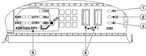
The following figure shows the Cisco ASR 1000 Series Route Processor faceplate.

Figure 1. Cisco ASR1000-RP Route Processor Faceplate LEDs and Connectors

1

Internal hard drive LED

4

USB 0, USB 1 connector

2

External USB Flash LED

5

ASR1000-RP1 or ASR1000-RP2 LEDs

3

Internal USB bootflash LED

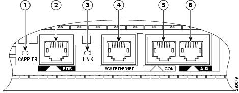
The following figure shows the Cisco route processor with faceplate connectors.

Figure 2. Cisco ASR1000-RP Route Processor Connectors

1

CARRIER LED

4

MGMT Ethernet connector

2

BITS connector

5

CON connector

3

LINK LED

6

AUX connector

The following table lists the Cisco ASR 1000 Series Route Processor LEDs and behavior.

Table 6. Cisco ASR 1000 Series Route Processor LEDs

LED Label

LED

Color —State

Behavior Description

PWR

Power

Solid green

All power requirements are within specification

Off

Off, the router is in standby mode.

STAT

System status

Solid green

Cisco IOS software has booted.

Yellow

ROMMON has successfully loaded.

Red

System failure or during boot process.

ACTV

Active

Green

Lit when the Cisco ASR 1000 Series RP is active.

STBY

Standby

Yellow

Lit when the Cisco ASR 1000 Series RP is the standby processor.

CRIT

Critical

Solid Red

Critical alarm indicator or during boot process. An example: the ambient air temperature is above 60ºC and will begin shutdown in 5 minutes.

MAJ

Major

Solid Red

Major alarm indicator. For example: Ambient air temperature is beyond short term operating range of 55ºC. System will shut down above 60ºC.

MIN

Minor

Amber

Minor alarm indicator. Ambient air temperature is beyond normal operating range of 40ºC. For example: if the RP software determines that an unknown card has been installed or if the card has failed, the card can power it off or set a minor alarm.

DISK HD

Internal hard drive LED

Flashing Green

Activity indicator.

Off

No activity.

DISK USB

External USB Flash

LED

Flashing Green

Activity indicator.

Off

No activity.

DISK BF

Internal USB bootflash LED

Flashing Green

Activity indicator.

Off

No activity.

BITS I/F Mode CARRIER

LED

Off

Out of service or not configured.

Solid Green

In frame and working properly.

Amber

Fault or loop condition exists.

DTI ModeCARRIER

for Cisco ASR1000-RP2

LED

Off

Warmup, Free-run, or Holdover.

Solid Green

Normal or bridging.

Amber

Fast.

LINK

10/100/1000 RJ-45 Interface LED

Solid Green

Link with no activity.

Flashing Green

Link with Activity.

Off

No link.

The following table lists the Cisco ASR 1000 Series Route Processors connectors and description.

Table 7. Cisco ASR 1000 Series Route Processor Connectors

Label

Type

Description

ACO

Audible Cutoff button

A recessed button to cut off the audible alarm. This is triggered when the critical, major, or minor LED is set.

0

USB0 interface

Side-by-side USB connector used with memory sticks or smart cards for secure key distribution

1

USB1 interface

Side-by-side USB connector used with memory sticks or smart cards for secure key distribution

BITS

RJ-45 connector

Indicates BITS timing reference.

MGMT ETHERNET

One RJ-45 jack for copper Ethernet Management Port

The route processor has an ENET port with a RJ-45 connector to attach a management device or network for network management.

CON

One RJ-45 for CON/AUX

Console port used to connect to a terminal.

AUX

One RJ-45 for CON/AUX

Auxiliary port used for remote management purposes.


Note

Out of Band (OOB) or modem connection in the AUX and/or CON ports, regardless of being properly configured, the connection is not established and a call cannot be setup. This functionality is not supported on any of the Cisco ASR 1000 Series Aggregation Services Routers or on any of the Cisco IOS XE versions.


The Cisco ASR 1000 Series Route Processor meets the following requirements:

  • Supports up to 4 GB of memory with single-bit error correction and multi-bit error detection (except for the Cisco ASR 1002 embedded route processor)
  • Supports On-board Failure Logging (OBFL) with 2MB of memory
  • Supports the Cisco ASR 1000 Series Router system architecture and midplane
  • Enhanced Serdes Interconnect (ESI) at 11.5 Gbps.
  • Gigibit Ethernet switches for EOBC communication and boot-up of the Cisco ASR 1000 Series SPA Interface (SIP) and Cisco ASR 1000 Series Embedded Services Processor.
  • Runs Cisco IOS network control plane (routing protocol, connections setup)
  • Cisco IOS punt packet forwarding
  • Active/Standby Cisco ASR 1000 Series Route Processor 1 and Cisco ASR 1000 Series Embedded Services Processor selection
  • Code storage and download operational code to Cisco ASR 1000 Series Embedded Services Processor and Cisco ASR 1000 Series SPA Interface (SIP)
  • Bulk storage: by default, it comes with a 40 GB hard disk drive (HDD).

Note

The HDD on ASR1000 products may have capacity in excess of that defined in the datasheet. However, during manufacturing, steps may be taken to reduce the capacity visible to the IOS, so that the visible size matches to the size specified in the datasheet.
  • 2 MB upgradeable BootROM, 1 GB Embedded USB memory (eUSB)
  • Comes with 2 GB of DRAM as default and can be upgradeable to 4 GB DRAM (except for the Cisco ASR 1002 embedded route processor).
  • Front panel support: Console, 10/100 Management port, two USB ports, CON port, and AUX port.The Cisco ASR 1000 Series Routers have one Gigabit Ethernet Management Ethernet interface on each Route Processor. The purpose of this interface is to allow users to perform management tasks on the router; it is basically an interface that should not and often cannot forward network traffic but can otherwise access the router, often via Telnet and SSH, and perform most management tasks on the router. The interface is most useful before a router has begun routing, or in troubleshooting scenarios when the SPA interfaces are inactive. The following aspects of the Management Ethernet interface should be noted:
    • Each RP has a Management Ethernet interface, but only the active RP has an accessible Management Ethernet interface (the standby RP can be accessed using the console port, however).
    • IPv4, IPv6, and ARP are the only routed protocols supported for the interface.
    • The interface provides a method of access to the router even if the SPA interfaces or the IOS processes are down.
  • A console port can run up to 115.2 kbps with hardware flow control. One port is used as the CONSOLE port for secure configuration and status display. The default BAUD rate for the CONSOLE port should be set at 9600 BAUD. Both the console and auxiliary ports are asynchronous serial ports.

Cisco Integrated ASR1000-RP1 for Cisco ASR 1002 Router

The route processor for the Cisco ASR 1002 Router is integrated in the chassis and supports all the typical customer management interfaces such as the Ethernet network management port and console and auxiliary serial ports of the route processor for the Cisco ASR 1006 and ASR 1004 routers. It also has LED status indicators, an RJ-45 plug for a BITS timing reference and one USB ports which can be used with smart cards for secure key distribution or for image or configuration file updates.

The following figure shows the Cisco ASR1000-RP1 LEDs for the Cisco ASR 1002 Router.

Figure 3. Embedded Cisco ASR1000-RP1 LEDs

The embedded route processors for the Cisco ASR 1002 Router provides connection for one SPA bay and the circuitry for the a built-in 4xGE SPA.

The Cisco route processor for ASR 1002 Router meets the requirements of route processors for the Cisco ASR 1006 and the Cisco ASR 1004 routers; except for the following deviations:

  • No SATA hard drive supported. Bulk file storage is on a large fixed eUSB device (up to 8 GB (bytes) supported).
  • No support for redundant route processors.
  • Hardware memory and storage options (such as DRAM) are not field upgradeable.
  • Network clock changes. No second BITS clock input supported.
  • The LED order is from top to bottom on the route processor is MIN, MAJ, CRIT.
  • The Cisco ASR1000-RP2 is not supported on the Cisco ASR 1002 router or Cisco ASR 1002-F router

The following table lists the Cisco embedded ASR1000-RP1 LEDs and behaviors.

Table 8. Cisco Embedded ASR1000-RP1 LEDs in the Cisco ASR 1002 Router

LED Label

LED

Color —State

Behavior Description

PWR

Power

Solid green

All power requirements are within specification

Off

Off, the router is in standby mode.

STAT

System status

Solid green

Cisco IOS has successfully booted.

Yellow

ROMMON is running or when the Process Manager declares that a critical ASR 1000 Series RP1 process is not running

Red

System failure or powering up.

MIN

Minor

Amber

Minor alarm indicator.

MAJ

Major

Red

Major alarm indicator.

CRIT

Critical

Red

Critical alarm indicator.

BOOT

eUSB0 FLASH(BootDisk

Flashing Green

Activity indicator.

Off

No activity.

CARRIER

Off

Out of service or not configured.

Green

In frame and working properly.

Amber

Fault or loop condition.

LINK

10/100 /1000 RJ-45 Interface LED

Green

Link with no activity.

Flashing Green

Link with activity.

Off

No link.

4 LEDs

Built-in SPA SFP port status

Off

Port is not enabled.

Amber

Port enabled but there is a problem with the Ethernet link.

Green

Port enabled, valid Ethernet link

PWR

Carrier card power

Green

All carrier card requirements are within specification.

STAT

Carrier card status

Green

Only when the SPA drivers have started and are running and all critical processes are running

Yellow

When ROMMON is running and during the download and boot of the operating system

Red

A fault is detected or the card is powering up.

The built-in Gigabit Ethernet ports on the Cisco ASR 1002 Router support the same small form-factor pluggable (SFP) optical transceivers as the 5x1 GE SPA. Note that the Cisco ASR 1002 built-in GE ports support only the SFP-GE-T but not the SFP-GLC-T.

The following table lists the Cisco embedded ASR1000-RP1in the Cisco ASR 1002 Router connectors and description.

Table 9. Cisco Embedded ASR1000-RP1 Connectors

Label

Type

Description

BITS

Standard E1/T1 RJ-45 connector

Indicates BITS timing references.

MGMT

One RJ-45 jack for copper Ethernet Management Ethernet Port

The route processor has an ENET port with a RJ-45 connector to attach a management device or network for network management.

CON

One RJ-45 for CON

Console port used to connect to a terminal.

AUX

One RJ-45 for AUX

Auxiliary port used for remote management purposes.

xref fig shows a fully loaded Cisco ASR 1002 Router.

1

F0 slot

3

The eUSB panel door on the side of the Cisco ASR 1002 Router must not be opened. There is a Do Not Tamper label on the panel door. Do not remove the label. If there is a problem with eUSB flash card, the chassis should be returned.

2

R0 slot

4

Grounding stud location


Note

Unless otherwise noted, features for the Cisco ASR 1002-F Router are the same as the Cisco ASR 1002 Router. The Cisco ASR1002-ESP-F supports 2.5 Gbps, and it is integrated in the chassis. It is not a field-replaceable unit.

How Cisco ASR1000-RP Alarm Monitoring Works

The Cisco ASR1000-RP1 or Cisco ASR1000-RP2 faceplate displays the CRIT, MAJ, and MIN alarm indicator LEDs. An external element can be connected to a power supply using the DB-25 alarm connector on the power supply. The external element is a DC light bulb for a visual alarm and a bell for an audible alarm.

If an alarm illuminates the CRIT, MIN, or MAJ LED on the Cisco ASR 1000 Series Route Processor (RP) faceplate, and a visual or audible alarm is wired, the alarm also activates an alarm relay in the power supply DB-25 connector (on the Cisco ASR 1006 Router and Cisco ASR 1004 Router). The bell rings or the light bulb flashes and alerts site personnel that a router alarm condition exists.


Note

Shielded cables must be used to connect to the DB-25 alarm connector on both the AC and DC power supplies, in order to comply with the FCC/EN55022/CISPR22 Class A emissions requirements.

The alarm signals sent to this DB-25 connector are identical in function to those sent to the system LEDs on the Cisco ASR1000-RP1 and Cisco ASR1000-RP2. Each alarm consists of three contact pins that are switched when an alarm becomes active which causes a corresponding contact closure between the DB-25 connector pins. As a result a critical, major, or minor alarm condition detected in the router can trigger a simultaneous fault indication in some of the following ways:

  • System alarm LEDs—The three system alarm LEDs on the Cisco ASR1000-RP1 and RP2 faceplate constitute the standard method of alarm notification in the router. These LEDs indicate router status at all times, but you must directly observe these LEDs to become aware of a router alarm condition See xref table for LED descriptions.
  • External alarm monitoring facility—By equipping your router with a telco-style external alarm monitoring facility, you can provide a more physical indication of router status. A visual alarm, however, can be reset only by resolving the problem that caused the alarm condition.

An external audible alarm can be reset by clearing the condition that caused the alarm or by pressing the Audible Cutoff (ACO) button on the Cisco ASR1000-RP1 and RP2. An audible alarm can be sounded to immediately alert you of an alarm condition in the router. An audible alarm generated by the system continues to sound until you either clear the alarm condition itself or press the ACO button to silence the alarm. Pressing this button does not resolve the alarm condition.

  • To clear an audible alarm, do one of the following:
    • Press the Audible Cut Off button on the route processor faceplate (see xref fig)
    • Enter the clear facility-alarm command.
  • To clear a visual alarm, you must resolve the alarm condition. The clear facility-alarm command does not clear an alarm LED on the RP faceplate or turn off the DC light bulb. For example, if a critical alarm LED is illuminated because an active SPA was removed without a graceful deactivation of the SPA, the only way to resolve that alarm is to replace the SPA.

Note

For alarm relay pinouts, see xref table for Cisco ASR 1006 router and xref table for Cisco ASR 1004 router.

Cisco ASR 1000 Series Router Power Supplies

All Cisco ASR 1000 Series Router configurations support AC and DC power supply options. The modular chassis configurations support the installation of two power supplies for redundancy. When an external power supply fails or is removed, the other power supply provides power requirements for the chassis.

You are required to always have two power supplies installed in the chassis to insure sufficient cooling for the box. The system fans are inside the power supply unit and must spin for cooling. No Cisco ASR 1000 Series Router will operate for more than two to three minutes without two power supplies installed. Since all the system fans can be powered by one power supply, it is not required for the second power supply unit to be powered on, but it must be installed. Cisco IOS software specifically looks for two power supplies in the chassis and will automatically initiate a shutdown if only one power supply is detected.

This section contains the following topics:

Power Supply Requirements for All Cisco ASR 1000 Series Routers

This section contains power supply specifications for all Cisco ASR 1000 Series Routers. The following topics are covered:

  • DC power supply input ratings and circuit breaker specifications
    • Maximum and minimum Amps for the branch circuit breakers
    • Maximum and minimum size of the AWG wire required for each circuit breaker.
  • AC and DC power supply types
  • AC and DC power supply ratings

DC Power System Input Requirements for Cisco ASR 1000 Series Routers

The DC power supply for the Cisco ASR 1006, Cisco ASR 1004, Cisco ASR 100, Cisco ASR 1013, and Cisco ASR 1001 routers operate at individual specifications.

The following table shows the common input ranges and circuit breaker requirements.

Table 10. Cisco ASR 1000 Series Router DC Power Supply System Input Requirements

Cisco ASR 1000 Series Router DC Power Supply

System Input Rating (Amps)

Circuit Breaker Amps

AWG # Wire

Minimum

Maximum

Minimum

Maximum

Cisco ASR 1006

40

Always 50

Always AWG #6 wire

Cisco ASR 1004

24

30

40

10

8

Cisco ASR 1002:

  • –48 VDC
  • +24 VDC

16

20

30

12

10

32

40

40

8

8

Cisco ASR 1013

40

Always 50

Always AWG #6 wire

Cisco ASR 1001

14

20

30

10

10

Cisco ASR 1002-X:

  • –48 VDC
  • +24 VDC

16

20

30

12

10

32

40

40

8

8

For example, the Cisco ASR 1002 Router DC power supply, with 16 Amp input rating must use an AWG #12 gauge wire for a 20 A circuit breaker and an AWG #10 gauge wire for a 30 A circuit breaker.


Note

All Cisco ASR 1000 Series Router AC power supplies must be connected to a branch circuit that does not exceed 20 A.

AC and DC Power Supply Types

The AC and DC power supplies for the Cisco ASR 1000 Series Routers support different types of power supply switches. The following table defines which power supplies the Cisco ASR 1000 Series routers support (a standby or an On/Off switch).

Table 11. Cisco ASR 1000 Series Routers AC and DC Power Supply Switches

Switch Type Supported

Symbol

Cisco ASR 1000 Series Router Power Supply

On/Off circuit

I/O

ASR 1006 –48 VDC

ASR 1004 –48 VDC

ASR 1002 AC

ASR 1002-X AC

Standby switch

A broken circle with a vertical line through the top of it

ASR 1006 AC

ASR 1004 AC

ASR 1002 –48 VDC

ASR 1002 +24 VDC

ASR 1013 AC and DC

ASR 1001 AC and DC

ASR 1002-X –48 VDC

ASR 1002-X +24 VDC

AC and DC System Power Ratings

The following table lists AC and DC power supply system rating requirements for all Cisco ASR 1000 Series Routers.

Table 12. AC and DC Power Supply System Rating Specifications for the Cisco ASR 1000 Series Routers

Description

Specification

Power supply declared ratings

AC = 100-240 VAC

DC = –48/ –60 VDC

+24 VDC = +21 / +36 VDC

Nominal line frequency rating

50/60 Hz for AC power supplies

Power Supplies for the Cisco ASR 1006 Router


Note

The information in this section applies to the ASR1006-PWR-DC and ASR1006-PWR-AC power supplies. The Cisco ASR 1006 Router also supports the ASR1013/06-PWR-DC and ASR1013/06-PWR-AC power supplies, which are described in the Power Supplies for the Cisco ASR 1013 Router.

The Cisco ASR 1006 Router can support up to 1200 W output (AC and –48 VDC input). The 1200 W power supply module consists of either an AC or –48 VDC input and 1200 watt output closed frame power supply with two DC voltage outputs: 12 V and 3.3 V.

Each power supply module contains three internal fan modules and provides the forced air cooling for the chassis. These power supply modules contain a monitor circuit to determine the status of fan speed and operation along with LED status indicating fan errors.

The system temperature operation is 0 to 40C normal and –5C to +55C.

  • AC System—AC power input is an IEC 320-type power inlet, 20A service connector. The AC input side contains a front panel with provisions for mounting screw, built in handle to extract the power supply, three status LEDs, and fans for power supply and system cooling.
  • –48 VDC System—Two-position terminal block-style connector, with labeled connections for - (–48/60 V input) and + (–48/60 V Return). The –48 VDC input side contains a front panel with provisions for mounting screw, built in handle to extract the power supply, three status LEDs, and fans for power supply and system cooling.

See xref Appendix A, “Cisco ASR 1000 Series Router Specifications for detailed power supply specifications.


Warning

This product relies on the building’s installation for short-circuit (overcurrent) protection. Ensure that the protective device is rated not greater than: AC power supplies for the Cisco Aggregation Services Routers: 120 VAC, 20A U.S. maximum. DC power supplies for the Cisco ASR 1006 Router: 50A U.S. maximum; Cisco ASR 1004 Router: 40A U.S. maximum: Cisco ASR 1002 Router: 30A U.S. maximum. Statement 1005


AC Power Supply LEDs and Connector for Cisco ASR 1006


Note

The information in this section applies to the ASR1006-PWR-AC power supply. If you are using the ASR1013/06-PWR-AC power supply, see the xref c_AC_Power_Supply_LEDs_and_Connector_for_Cisco_ASR_1013_1206731.xml.

The power supply module contains three fans. A total of six fans are used to cool the ASR 1006 system and power supply. The airflow direction is front to back.

Power supply modules with internal fan modules install into the rear of the chassis. These modules contain integral handles to ease installation and removal (no insertion or extraction levers are provided). A single blind mate connector located on the inlet side of these modules mates with a connector mounted on back side of the midplane.

Guide pins located at the rear of these modules help center locate the modules and reduce stress to the midplane and module mounted connectors. Four captive screws (tool operated latches) are provided on the modules face plate (chassis rear) to secure these modules into the chassis.

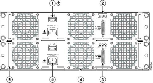
xref fig shows the ASR1006-PWR-AC power supply of the Cisco ASR 1006 Router. The Cisco ASR 1006 Router supports up to two power supplies. The power supply LEDs and connectors on the rear of the chassis are described in xref table.

1

AC power supply fan

5

AC power supply handle

2

DB-25 alarm connector

6

AC power inlet

3

Tie-wrap tab

7

AC power supply standby switch

4

AC power supply captive screw

8

AC power supply LEDs

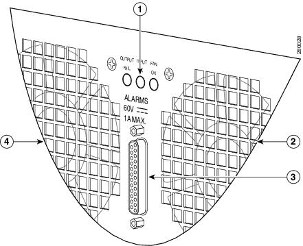
The following figure shows the AC power supply LEDs and DB-25 alarm connector.

Figure 4. Cisco ASR 1006 Router AC Power Supply LEDs and DB-25 Alarm Connector

1

AC power supply LEDs

3

DB-25 alarm connector

2

AC power supply fan

4

AC power supply fan

The following table describes the AC power supply LEDs on the Cisco ASR 1006 Router.

Table 13. Cisco ASR 1006 Router AC Power Supply LEDs

LED Label

LED

Color

Description

INPUT OK

Power supply activity

Green

LED illuminates green to signal that the AC power supply input voltage is greater than 85 V.

None

If LED is not illuminated, then the AC input voltage is less than 70 V or the power supply is turned off. For an AC input voltage between 70 V and 85V, the INPUT OK LED can be either on, off, or flashing

FAN OK

Bi-color LED indicates fan status

Green

LED illuminates green when all fans are operational.

Red

The LED illuminates red when a fan failure is detected.

OUTPUT FAIL

Power supply activity

Red

LED is red and turned off to signal that the -48 VDC output voltages are within the normal operating range; output voltage between the minimum and maximum limits will not create an output fail alarm, and output voltages below the minimum or above the maximum will create an output fail alarm.

When you turn the power supply on, the red LED is illuminated for two to three seconds for testing LED operation before going off.

–48 VDC Power Supply LEDs and Connectors for Cisco ASR 1006


Note

The information in this section applies to the ASR1006-PWR-DC power supply. If you are using the ASR1013/06-PWR-DC power supply, see the xref c_–48_VDC_Power_Supply_LEDs_and_Connectors_for_Cisco_ASR_1013_1206865.xml.

The maximum branch circuit for the –48 VDC power supply module is 60 A and the minimum is 50 A. The –48 VDC power supply operates within specification from –48 VDC to –60 VDC continuously. The Cisco ASR 1006 Router has two of the same type power supplies in power supply slot 0 and power supply slot 1. The power supply slot numbers are on the left side of the chassis and the power supplies are located on the floor of the chassis.

The –48 VDC input connector is a terminal block style that supports a AWG #6 wire. The terminal block is compliant with safety agencies’ guidelines and electrical requirements of the supply. Use the tie wraps to dress the input cable wires. There are three tie wrap tabs on the power supply.

The terminal block accepts two double-hole lugs, one for –48 V input and another for –48 V RTN. A plastic cover fits over the terminal block to prevent accidental contact. See xref figure.


Note

The studs on the terminal block are similar to the safety ground device on the side of the Cisco ASR 1006 Router. For information on the safety ground lug on the side of the chassis.

The unit requires a power switch circuit breaker to serve as the main disconnect for the –48 VDC input to the power supply. The circuit breaker meets international safety requirements and supports 80 VDC and has a current rating of 50 A. The power supply unit is secured into the system chassis with four captive screws mounted on the faceplate.

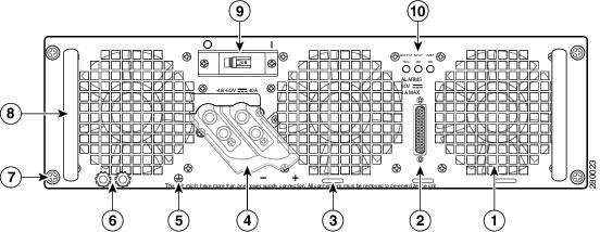
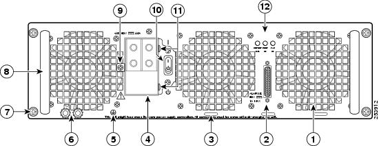
The following figure shows the –48 VDC power supplies at the rear of the Cisco ASR 1006 Router. The Cisco ASR 1006 Router supports up to two power supplies.

Figure 5. Cisco ASR 1006 Router –48 VDC Power Supply

1

Fans

6

Ground lugs

2

DB-25 alarm connector

7

Captive screws

3

Tie-wrap tabs

8

Power supply handle

4

Terminal and plastic cover

9

Power supply On (|) /Off (O) switch

5

Grounding symbol

10

Power supply LEDs

The following table describes the power supply LEDs and connectors on the rear of the chassis.

Table 14. Cisco ASR 1006 Router –48 VDC Power Supply LEDs

LED Label

LED

Color

Description

INPUT OK

A bi-color LED indicates presence of input voltage

Green

LED illuminates green to signal that the –48 VDC power supply input voltage is greater than–43.5VDC at turn-on and remains green down to –39VDC.

Amber

The LED illuminates amber when the input voltage (falls below –39VDC) and indicates that there is still a voltage present (voltage on the terminal block). The LED remains amber and is active to around 20 V +/-5 V. The LED is not illuminated if the input is below –15 V.

FAN OK

A bi-color LED indicates power supply fan status

Green

The LED illuminates s green when all fans are operational.

Red

The LED illuminates red when a fan failure is detected.

OUTPUT FAIL

Power supply activity

Red

When the LED is off, it signals that the –48 VDC output voltage are within the normal operating range. Output voltage between the minimum and maximum limits will not create an output fail alarm, and output voltages below the minimum or above the maximum will create an Output Fail alarm.

When you turn the power supply on, the red LED illuminates for two to three seconds to test LED operation before going off.

AC/DC Power System Output for Cisco ASR 1006

The power supply output tolerance is defined in the following table under all combinations of line variation. Total system consumption per power supply should not exceed 1200 W.

Table 15. Cisco ASR 1006 Router Power System Output Voltage and Current

Output Voltage

+12 VDC

+3.3 V

Minimum

11.80 VDC

3.20 VDC

Nominal

12.00 VDC

3.30 VDC

Maximum

12.20 VDC

3.40 VDC

Output Current

Minimum

2.80 A

0.10 A

Maximum

101.7 A

3.125 A

Power Supplies for the Cisco ASR 1004 Router

The Cisco ASR 1004 Router can support up to 735 W output (AC and –48 VDC input). The 735 W power supply module consists of either an AC or –48 VDC input with two DC voltage outputs: 12 V and 3.3 V.

Each power supply module contains three internal fan modules and provides the forced air cooling for the chassis. These power supply modules contain a monitor circuit to determine the status of fan speed and operation along with LED status indicating fan errors.

The system temperature operation is 0 to 40C and –5C to +55C.

  • AC System—AC power input is an IEC 320-type power inlet, 15A service connector. The AC input side contains a front panel with provisions for mounting screw, built in handle to remove the power supply, three status LEDs, and fans for power supply and system cooling.
  • DC System—Three-position terminal block-style connector, with labeled connections for - (–48/60 V input) and + (–48/60 V Return) and GND (ground symbol). The –48 VDC input side contains a front panel with provisions for mounting screw, built in handle to extract the power supply, three status LEDs, and fans for power supply and system cooling.

See xref Appendix A, “Cisco ASR 1000 Series Router Specifications” for detailed power supply specifications.


Warning

This product relies on the building’s installation for short-circuit (overcurrent) protection. Ensure that the protective device is rated not greater than: AC power supplies for the Cisco Aggregation Services Routers: 120 VAC, 20A U.S. maximum. DC power supplies for the Cisco ASR 1006 Router: 50A U.S. maximum; Cisco ASR 1004 Router: 40A U.S. maximum: Cisco ASR 1002 Router: 30A U.S. maximum. Statement 1005


Cisco ASR 1004 AC Power Supply

This section provides information about the AC power supplies on the rear of the Cisco ASR 1004 Router. The power supply module contains three fans. A total of six fans are used to cool the ASR 1004 system and power supply. The airflow direction is front to back.

Power supply modules with internal fan modules install into the rear of the chassis. These modules contain handles to ease installation and removal. The AC power supply has a front panel mounted switch that powers on and off the power supply. This switch will not disconnect the AC line, but will act only as a standby switch to the power supply. The front panel includes a mechanical guard to prevent the standby switch from being tripped due to accidental contact.

Guide pins located at the rear of these modules help center locate the modules and reduce stress to the midplane and module mounted connectors. Four captive screws (tool operated latches) are provided on the modules face plate (chassis rear) to secure these modules into the chassis.

Cisco ASR 1004 AC Power Supply LEDs and Connector

The following figure shows the AC power supplies at the rear of the Cisco ASR 1004 Router.The Cisco ASR 1004 Router supports up to two power supplies.

Figure 6. Cisco ASR 1004 Router AC Power Supply

1

AC power supply standby switch (standby symbol is a broken circle with a vertical line through the top of it)

4

AC power supply fan

2

AC power supply LEDs

5

AC power inlet

3

DB-25 alarm connector

6

AC power supply handle

The following figure shows the AC power supply LEDs and DB -25 alarm connector.

Figure 7. Cisco ASR 1004 Router AC Power Supply LEDs and DB -25 Alarm Connector

1

AC power supply LEDs

3

DB-25 alarm connector

2

Power supply fan

4

AC power supply fan

The following table describes the power supply LEDs and connectors on the rear of the chassis.

Table 16. Cisco ASR 1004 Router AC Power Supply LEDs and Connector

LED Label

LED

Color

Description

INPUT OK

Power supply activity

Green

LED illuminates green to signal that the AC power supply input voltage is greater than 85 V.

None

If LED is not illuminated, then the AC input voltage is less than 70 V or the power supply is turned off. For an AC input voltage between 70 V and 85V, the INPUT OK LED can be either on, off, or flashing

FAN OK

Bi-color LED indicates fan status

Green

LED illuminates green when all fans are operational.

Red

The LED illuminates red when a fan failure is detected.

OUTPUT FAIL

Power supply activity

Red

LED is red and turned off to signal that the –48 VDC output voltages are within the normal operating range; output voltage between the minimum and maximum limits will not create an output fail alarm, and output voltages below the minimum or above the maximum will create an output fail alarm.

When you turn the power supply on, the red LED is illuminated for two to three seconds for testing LED operation before going off.

Cisco ASR Router 1004 –48 VDC Power Supply

This section provides information about the –48 VDC power supplies on the rear of the Cisco ASR 1004 Router. For the maximum branch circuit for the –48 VDC power supply module, see xref table.

The –48 VDC power supply operates within specification from –48 VDC to –60 VDC continuously. The Cisco ASR 1004 Router has two of the same type power supplies in power supply slot 0 and power supply slot 1. The power supply slot numbers are on the left side of the chassis and the power supplies are located on the floor of the chassis.

The –48 VDC power supply input connector is a terminal block style that will allow crimp type lugs accepting up to AWG #8 wire. The terminal block is compliant with safety agencies’ guidelines and electrical requirements of the supply. The terminal block accepts two-hole lugs (#10 stud) for all connections with center to center spacing of 0.625 inches. A plastic cover goes over the terminal block to prevent accidental contact. The connection order is negative (–), positive (+), and GND.

The unit requires a power switch circuit breaker to serve as the main disconnect for the –48 VDC input to the power supply (xref table see for current rating requirements.) The power supply unit is secured into the system chassis with four captive screws mounted on the faceplate.

Cisco ASR 1004 Router –48 VDC Power Supply LEDs and Connector

The following figure shows the –48 VDC power supplies at the rear of the Cisco ASR 1004 Router. The Cisco ASR 1004 Router supports up to two power supplies.

Figure 8. Cisco ASR 1004 Router –48 VDC Power Supply

1

Terminal and plastic cover

5

Grounding symbol

2

Power supply LEDs

6

Power supply On (|) /Off (O) switch

3

DB-25 alarm connector

Power supply ground lugs (+ and –)

7

Power supply handle

4

Power supply fan

The following table describes the power supply LEDs and connectors on the rear of the chassis.

Table 17. Cisco ASR 1004 Router –48 VDC Power Supply LEDs

LED Label

LED

Color

Description

INPUT OK

A bi-color LED indicates presence of input voltage

Green

LED illuminates green to signal that the –48 VDC power supply input voltage is greater than–43.5VDC at turn-on and remains green down to –39VDC.

Amber

The LED illuminates amber when the input voltage (falls below –39VDC) and indicates that there is still a voltage present (voltage on the terminal block). The LED remains amber and is active to around 20 V +/-5 V. The LED is not illuminated if the input is below –15 V.

FAN OK

A bi-color LED indicates power supply fan status

Green

The LED illuminates s green when all fans are operational.

Red

The LED illuminates red when a fan failure is detected.

OUTPUT FAIL

Power supply activity

Red

When the LED is off, it signals that the –48 VDC output voltage are within the normal operating range. Output voltage between the minimum and maximum limits will not create an output fail alarm, and output voltages below the minimum or above the maximum will create an Output Fail alarm.

When you turn the power supply on, the red LED illuminates for two to three seconds to test LED operation before going off.

DC Power System Input for Cisco ASR 1004

The –48 VDC power supply operates within specification from –40.5VDC to –72VDC continuously once the power supply –48 VDC input turn on threshold of –43.5 V has been reached. The following table shows the common input ranges for reference only.

Table 18. Cisco ASR 1004 Router –48 VDC Power System Input

Voltage Range (VDC)

Minimum

Nominal

Maximum

Domestic

–40.5

–48

–56

International

–55

–60

–72

AC/DC Power System Output for Cisco ASR 1004

The power supply output tolerance is defined in the following table under all combinations of line variation. Total system consumption per power supply should not exceed 735 W.

Table 19. Cisco ASR 1004 Router Power System Output Voltage and Current

Output Voltage

+12 VDC

+3.3 V

Minimum

11.80 VDC

3.20 VDC

Nominal

12.00 VDC

3.30 VDC

Maximum

12.20 VDC

3.40 VDC

Output Current

Minimum

2.80 A

0.10 A

Maximum

61.44A

3.125 A

Power Supplies for the Cisco ASR 1002 Router


Note

Unless otherwise noted, the Cisco ASR 1002-F Router and the Cisco ASR 1002-X Router supports all the general-purpose routing and security features of the Cisco ASR 1002 Router and uses the same internal control and data-plane architecture as Cisco ASR 1002 Router. The Cisco 24 V power supply is currently supported only on the Cisco ASR 1002 Router and the Cisco ASR 1002-X Router but not on the Cisco ASR 1002-F Router.

The Cisco ASR 1002 Router supports an AC or –48 VDC power supply and a +24 VDC power supply:

Cisco ASR 1002 Router Power Supply Fans

Cisco ASR 1002 Router system level cooling is provided by two 12 VDC type fans in each power supply module. The fans in each module provide system cooling back-up in the event of a single fan failure. In addition, the fans in each of the power supplies can be powered from a single supply when only one unit is operational. The airflow direction is front to back.


Warning

This product relies on the building’s installation for short-circuit (overcurrent) protection. Ensure that the protective device is rated not greater than: AC power supplies for the Cisco Aggregation Services Routers: 120 VAC, 20A U.S. maximum. DC power supplies for the Cisco ASR 1006 Router: 50A U.S. maximum; Cisco ASR 1004 Router: 40A U.S. maximum: Cisco ASR 1002 Router: 30A U.S. maximum. Statement 1005


Cisco ASR 1002 Router AC Power Supply

This section provides information about the AC power supplies on the rear of the Cisco ASR 1002 Router.

The Cisco ASR 1002 Router system level cooling is provided by two 12 VDC type fans in each of the two power supply modules. The fans in each module are intended to provide system cooling back-up in the event of a single fan failure. In addition, the fans in each of the power supplies can be powered from a single supply when only one unit is operational. The airflow direction is front to back. The power supplies plug directly into the Cisco ASR1000-RP1 and distributes power back to the midplane.

Guide pins located at the rear of these modules help center locate the modules and reduce stress to the midplane and module mounted connectors. Two captive screws (tool operated latches) are provided on the modules face plate (chassis rear) to secure these modules into the chassis.

Cisco ASR 1002 AC Power Supply LEDs and Connector

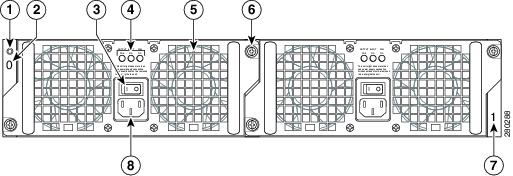
The following figure shows the AC power supplies at the rear of the Cisco ASR 1002 Router. The Cisco ASR 1002 Router supports up to two power supplies.

Figure 9. Cisco ASR 1002 Router AC Power Supply

1

Chassis ESD socket

5

AC power supply fan

2

AC power supply slot number 0

6

AC power supply captive installation screw

3

AC power supply On (|) /Off (O) switch

7

AC power supply slot number 1

4

AC power supply LEDs

8

AC power inlet

The following table describes the power supply LEDs and connectors on the rear of the chassis.

Table 20. Cisco ASR 1002 Router Power Supply LEDs

LED Label

LED

Color

Description

INPUT OK

Power supply activity

Green

The AC input voltage is greater than 85V.

None

If the LED is not illuminated, then either the input voltage is less than 70V, or the power supply is turned off.

If the AC input voltage is between 70V and 85V, the INPUT OK LED can be on, off, or flashing.

FAN OK

Power supply fan activity

A bi-color LED indicates fan status.

Green

All fans are operational.

Red

A fan failure is detected.

OUTPUT FAIL

Power supply activity

Red

If the INPUT OK LED is illuminated, this LED is red if the DC output voltages are below the minimum limit or above the maximum limit.

If the INPUT OK LED is not illuminated, this LED might be off or red.

AC Power System Output Voltage Alarm Range for Cisco ASR 1002 Router

The AC power supply output voltage alarm occurs when the output voltage is below the low end of the minimum or above the high end of the maximum limits shown in the following table.

Table 21. Cisco ASR 1002 Router AC Power Supply Output Voltage Alarm Range

Power Supply Type

Minimum

Maximum

12 V

10.0 to 11.2V

12.8 to 13.8 V

3.3 V

2.6 to 3.0 V

None

Cisco ASR 1002 Router –48 VDC Power Supply

This section provides information about the –48 VDC power supplies on the rear of the Cisco ASR 1002 Router. The recommended branch circuit breaker for the Cisco ASR 1002 Router –48 VDC power supply is 30 A. Use an AWG #10 maximum wire gauge on the 30 A circuit. The maximum branch circuit for the –48 VDC power supply module must not exceed 30 A.

The Cisco ASR 1002 Router has two of the same type power supplies in power supply slot 0 and power supply slot 1. The power supply slot numbers are on the left side of the chassis and the power supplies are located on the floor of the chassis. The power supply switch is a standby switch and is not considered a disconnect.

The –48 VDC input connector is a Euro-style terminal block. The largest size gauge of wire that the front panel euro-terminal block can accept is AWG #10 wire. The terminal block is compliant with safety agencies’ guidelines and electrical requirements of the supply. Use the tie wraps to dress the input cable wires; there are two tie wrap tabs on the –48 VDC power supply.

The –48 VDC power supply unit is secured into the system chassis with two captive screws mounted on the faceplate.

Cisco ASR 1002 Router –48 VDC Power Supply LEDs and Connector

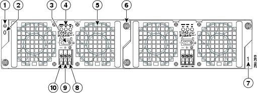
The following figure shows the –48 VDC power supplies at the rear of the Cisco ASR 1002 Router. The Cisco ASR 1002 Router supports up to two power supplies.

Figure 10. Cisco ASR 1002 Router –48 VDC Power Supply

1

Chassis ESD socket

6

Power supply captive installation screw

2

Power supply slot 0 label

7

Power supply slot 1 label

3

Power supply switch standby/On (|)

8

Ground lead

4

Power supply LEDs

9

Positive lead

5

Fan

10

Negative lead

The following table describes the power supply LEDs and connectors on the rear of the chassis.

Table 22. Cisco ASR 1002 Router –48 VDC Power Supply LEDs

LED Label

LED

Color

Description

INPUT OK

A bi-color LED indicates presence of input voltage

Green

LED illuminates green to signal that the –48 VDC power supply input voltage is greater than–43.5VDC at turn-on and remains green down to –39VDC.

Amber

The LED illuminates amber when the input voltage (falls below –39VDC) and indicates that there is still a voltage present (voltage on the terminal block). The LED remains amber and is active to around 20 V +/-5 V. The LED is not illuminated if the input is below –15 V.

FAN OK

A bi-color LED indicates power supply fan status

Green

The LED illuminates s green when all fans are operational.

Red

The LED illuminates red when a fan failure is detected.

OUTPUT FAIL

Power supply activity

Red

When the LED is off, it signals that the –48 VDC output voltage are within the normal operating range. Output voltage between the minimum and maximum limits will not create an output fail alarm, and output voltages below the minimum or above the maximum will create an Output Fail alarm.

When you turn the power supply on, the red LED illuminates for two to three seconds to test LED operation before going off.

–48 VDC Power System Input for Cisco ASR 1002 Router

The –48 VDC power supply operates within specification from –40.5VDC to –72VDC continuously once the power supply –48 VDC input turn on threshold of –43.5 V has been reached. The following table shows the common input ranges for reference only. The –48 VDC power input connector is a Euro-style terminal block that accepts three wires, one positive, one negative, and one grounding wire.

Table 23. Cisco ASR 1002 Router –48 VDC Power System Input

Voltage Range (VDC)

Minimum

Nominal

Maximum

Domestic

–40.5

–48

–56

International

–55

–60

–72

–48 VDC Power System Output for Cisco ASR 1002 Router

The –48 VDC power supply output tolerance is defined in the following table under all combinations of –48 VDC input line variation. Total system power consumption should not exceed 470 watts or output rating of each power supply.


Note

Two power supplies are used for redundant operation. System total power consumption shall never exceed rating of one power supply to maintain redundancy.
Table 24. Cisco ASR 1002 Router –48 VDC Power System Output Voltage and Current

Output Voltage

+12 VDC

+3.3 V

Minimum

–11.80 VDC

–3.20 VDC

Nominal

–12.00 VDC

–3.30 VDC

Maximum

–12.20 VDC

–3.40 VDC

Output Current

Minimum

–2.0 A

–0.10 A

Maximum

–39 A

–3.125 A

Cisco ASR 1002 Router +24 VDC Power Supply

This section provides information about the +24 VDC power supplies on the rear of the Cisco ASR 1002 Router. The recommended branch circuit breaker for the Cisco ASR 1002 Router +24 VDC power supply is a 40 A UL listed circuit breaker.

The Cisco ASR 1002 Router has two of the same type power supplies in power supply slot 0 and power supply slot 1. The power supply slot identifiers are zero (0) on the left side of the chassis rear and one (1) on the right side of the chassis rear. The power supply switch is a standby switch and is not considered a disconnect.

The +24 VDC power supply uses a spring-loaded terminal block. The input terminal block requires maximum 8AWG multi-strand wiring to support input current. The terminal block is compliant with safety agencies’ guidelines and electrical requirements of the supply. Use the tie wraps to dress the input cable wires; there are two tie wrap tabs on the +24 VDC power supply. The +24 VDC power supply unit is secured into the system chassis with two captive screws mounted on the faceplate.

Cisco ASR 1002 Router +24 VDC Power Supply LEDs and Connector

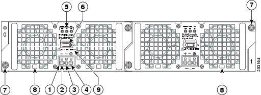
The following figure shows the +24 VDC power supplies at the rear of the Cisco ASR 1002 Router. The Cisco ASR 1002 Router supports two +24 VDC power supplies.

Figure 11. Cisco ASR 1002 Router Rear View With +24 VDC Power Supply

1

+24 VDC terminal block

6

Standby/On switch

2

Positive (+) lead

7

Captive fastener

3

Negative (-) lead

8

Power supply tabs

4

Ground (GND) lead

9

+27 VDC INPUT label

5

Power supply LEDs


Note

The +24 VDC power supply product is labeled at +27 VDC input because the typical battery float voltage is +27V; but generically, these power systems can be labeled +24 V and referred to as +24 VDC (see the following figure for more information).
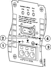
Figure 12. Cisco ASR 1002 Router Rear View With +24 VDC Power Supply Terminal Block

1

Positive (+) lead

6

GROUND (GND) LEAD

2

Negative (-) lead

7

+27VDC label

The following table describes the power supply LEDs and connectors on the rear of the chassis.

Table 25. Cisco ASR 1002 Router +24 VDC Power Supply LEDs

LED Label

LED

Color

Description

OUTPUT FAIL

Power supply activity

Red

When the LED is off, it signals that the +24 VDC output voltage are within the normal operating range. Output voltage between the minimum and maximum limits will not create an output fail alarm, and output voltages below the minimum or above the maximum will create an Output Fail alarm.

When you turn the power supply on, the red LED illuminates for two to three seconds to test LED operation before going off.

INPUT OK

A bi-color LED indicates presence of input voltage

Green

LED illuminates green to signal that voltage is > or = to 20VDC at turn-on and down to 19.0VDC (+/- 0.5 V tolerance).

Amber

The LED illuminates amber when the input voltage is active down to 16.0VDC and indicates that there is still a voltage present (voltage on the terminal block). The LED remains amber and is active to around 10 V. The LED can be OFF below 15.8VDC.

FAN OK

A bi-color LED indicates power supply fan status

Green

The LED illuminates s green when all fans are operational.

Red

The LED illuminates red when a fan failure is detected.

+24 VDC Power System Input for Cisco ASR 1002 Router

The +24 VDC power supply operates within specification between +21 and +36 VDC continuously once the power supply DC input is turned on. The power supply shall measure the input voltage at the terminals of the power supply and turn off the supply when the input voltage reaches 19.0 volts +/- 0.5 volts. Once this low voltage threshold is reached, the power supply does not resume operation until the input voltage has reached 20.0 volts +/- 0.5 volts. Once the turn-on threshold of 20 volts is reached, then the +24 VDC power supply meets all specification requirements down to low voltage threshold of 19 volts (+/- tolerance).

+24 VDC Power System Output for Cisco ASR 1002 Router

The +24 VDC power supply output tolerance is defined in the following table under all combinations of +24 VDC input line variation. Total system power consumption should not exceed 470 watts or output rating of each power supply.


Note

Two power supplies are used for redundant operation. System total power consumption shall never exceed rating of one power supply to maintain redundancy.
Table 26. Cisco ASR 1002 Router +24 VDC Power System Output Voltage and Current

Output Voltage

+12 VDC

+3.3 V

Minimum

11.80

3.20

Nominal

12.00

3.30

Maximum

12.20

3.40

Output Current

Minimum

2.0 A

0.10 A

Maximum

39 A

3.125 A


Note

Any combination of output voltage/currents cannot exceed total power rating of 470 Watts.
+24 VDC Power Supply Important Notices

The following items list important notes regarding the +24 VDC power supply in the Cisco ASR 1002 Router:

  • Output Voltage Alarm Threshold—The Output Voltage Alarm is declared when the output voltage is below the low end of the minimum or above the high end of the maximum limits (as shown in the following table). When the output voltage is above the high end of the minimum or below the low end of the maximum limits, then the Red state is not activated.
Table 27. +24 VDC Output Voltage Alarm Threshold Ranges

Output

Minimum

Maximum

12V

10.0-11.2V

12.8-13.8V

3.3V

2.6 – 3.0V

None

  • Temperature—If a single fan fails, the power supply meets the functional requirements specified in Table 24. Above 55°C with less than two fans, calculated MTBF does not apply; however all component stress remains within the manufacturer’s specified rating.
  • Thermal Shutdown—The +24 VDC power supply will shut down to protect its components due to excessive internal temperature. The +24 VDC power supply then automatically restarts if the internal temperature returns to a safe operating level.

Power Supplies for the Cisco ASR 1013 Router


Note

The information in this section applies to the ASR1013/06-PWR-DC and ASR1013/06-PWR-AC power supplies. These power supplies are supported by both the Cisco ASR 1013 Router and the Cisco ASR 1006 Router. However, the power zones mentioned in this section are supported only on the Cisco ASR 1013 Router.

The Cisco ASR 1013 Router can support up to 1600 W output and operates between 180 VAC and 260 VAC. The 1600 W power supply module consists of either an AC or –48 VDC input and 1600 watt output closed frame power supply with two DC voltage outputs: +12 V and +3.3 V can be used as a single supply, dual, triple, or quadruple hot pluggable system.


Note

The Cisco ASR 1013 router power supply +12 V is not bussed between the two power zones but the +3.3 V is bussed between them.

The Cisco ASR 1013 system has two power zones, each powered by two power supplies in a redundant configuration. Three power voltages are provided by the dual 1+1 configured power supplies, which are 12V_A, 12V_B, and 3.3V_BACKPLANE. The12V_A AND 121V_B are distributed to provide power to one half of the chassis each. A single (non-redundant) or a dual (1 + 1 redundant) supply configuration is able to support loads up to 1600 W on the 12 V and 10 W on the 3.3 V output.

Each power supply module contains three internal fan modules and provides the forced air cooling for the chassis. These power supply modules contain a monitor circuit to determine the status of fan speed and operation along with LED status indicating fan errors.

The system temperature operation is 0 to 40C normal and –5C to +55C.

AC System—AC power input is an IEC 320-type power inlet, 20 A service connector. The switch does not disconnect the AC line; but enables the signal to the power supply. The AC cord disconnects the power supply from the AC source. The unit is secured with four captive fasteners mounted on the faceplate (see xref Figure 2-15). The AC power supply input range operates within specification from 180 VAC to 264 VAC.

  • –48 VDC System—Two-position terminal block-style connector, with labeled connections for - (–48/60 V input) and + (–48/60 V Return). The –48 VDC input side contains a front panel with provisions for mounting screw, built in handle to extract the power supply, three status LEDs, and fans for power supply and system cooling.

The DC input range is –40.5 to –72 VDC.

See xref Appendix A, “Cisco ASR 1000 Series Router Specifications” for detailed power supply specifications.


Warning

This product relies on the building’s installation for short-circuit (overcurrent) protection. Ensure that the protective device is rated not greater than: AC power supplies for the Cisco Aggregation Services Routers: 120 VAC, 20A U.S. maximum. DC power supplies for the Cisco ASR 1013 Router and Cisco ASR 1006 Router: 50A U.S. maximum; Cisco ASR 1004 Router: 40A U.S. maximum: Cisco ASR 1002 Router: 30A U.S. maximum. Statement 1005


AC Power Supply LEDs and Connector for Cisco ASR 1013

This section provides information about the AC power supplies on the rear of the Cisco ASR 1013 Router. The power supply module contains three fans. A total of six fans are used to cool the ASR 1013 system and power supply. The airflow direction is front to back.


Note

The information in this section applies to the ASR1013/06-PWR-AC power supply. The Cisco ASR 1013 Router and the Cisco ASR 1006 Router support this power supply.

Power supply modules with internal fan modules install into the rear of the chassis. These modules contain integral handles to ease installation and removal (no insertion or extraction levers are provided).

Guide pins located at the rear of these modules help center locate the modules and reduce stress to the midplane and module mounted connectors. Four captive screws (tool operated latches) are provided on the modules face plate (chassis rear) to secure these modules into the chassis. The following figure shows the AC power supply for the Cisco ASR 1013 Router. The Cisco ASR 1013 Router supports up to four power supplies.

1

AC power supply fan

6

AC power inlet

2

DB-25 alarm connector

7

AC power supply standby switch

3

Tie-wrap tab

8

Protective shielding on both sides of the standby switch

4

AC power supply captive screw

9

AC power supply LEDs

5

AC power supply handle

The following figure shows the AC power supplies LEDs and DB-25 Alarm connector.

Figure 13. Cisco ASR 1013 Router AC Power Supply LEDs and DB-25 Alarm Connector

1

AC power supply LEDs

3

DB-25 alarm connector

2

AC power supply fan

4

AC power supply fan

The following table describes the AC power supply LEDs on the Cisco ASR 1013 Router.

Table 28. Cisco ASR 1013 Router AC Power Supply LEDs

LED Label

LED

Color

Description

INPUT OK

Power supply activity

Green

LED illuminates green to signal that the AC power supply input voltage is greater than 85 V.

None

If LED is not illuminated, then the AC input voltage is less than 70 V or the power supply is turned off. For an AC input voltage between 70 V and 85V, the INPUT OK LED can be either on, off, or flashing

FAN OK

Bi-color LED indicates fan status

Green

LED illuminates green when all fans are operational.

Red

The LED illuminates red when a fan failure is detected.

OUTPUT FAIL

Power supply activity

Red

LED is red and turned off to signal that the –48 VDC output voltages are within the normal operating range; output voltage between the minimum and maximum limits will not create an output fail alarm, and output voltages below the minimum or above the maximum will create an output fail alarm.

When you turn the power supply on, the red LED is illuminated for two to three seconds for testing LED operation before going off.

–48 VDC Power Supply LEDs and Connectors for Cisco ASR 1013

This section provides information about the –48 VDC power supplies on the rear of the Cisco ASR 1013 Router. The maximum branch circuit for the–48 VDC power supply module is 60 A and the minimum is 50 A.


Note

The information in this section applies to the ASR1013/06-PWR-DC power supply. The Cisco ASR 1013 Router and the Cisco ASR 1006 Router support this power supply.

The –48 VDC power supply operates within specification from –40.5 VDC to –72 VDC continuously. The Cisco ASR 1013 Router has two of the same type power supplies in power supply slot 0 and power supply slot 1. The power supply slot numbers are on the left side of the chassis and the power supplies are located on the floor of the chassis.

The –48 VDC input connector is a terminal block style that supports a AWG #6 wire. The terminal block is compliant with safety agencies’ guidelines and electrical requirements of the supply. Use the tie wraps to dress the input cable wires. There are three tie wrap tabs on the power supply.

The terminal block accepts two-hole lugs, one for the –48 V input and the other for the –48 V RTN. A plastic cover is fitted over the terminal block to prevent accidental contact.


Note

The studs on the terminal block are similar to the safety ground device on the bottom rear of the Cisco ASR 1013 Router. For information on the safety ground lug on bottom rear of the chassis, see the xref “Attaching a Chassis Ground Connection” section.

The unit requires a power switch circuit breaker to serve as the main disconnect for the –48 VDC input to the power supply. The circuit breaker meets international safety requirements and supports 80VDC and has a current rating of 50 A. The power supply unit is secured into the system chassis with four captive screws mounted on the faceplate.

The following figure shows the –48 VDC power supplies at the rear of the Cisco ASR 1013 Router. The Cisco ASR 1013 Router supports up to four power supplies.

Figure 14. Cisco ASR 1013 Router –48 VDC Power Supply

1

Fan

7

DC power supply captive screw

2

DB-25 alarm connector*

8

DC power supply handle

3

Tie-wrap tab

9

Terminal block and plastic cover single screw

4

DC power supply terminal block and plastic cover

10

On/Off (|/O) circuit breaker switch

5

Ground symbol

11

Terminal block and plastic cover slot tab

6

DC power supply ground studs

12

Power supply LEDs

The following table describes the power supply LEDs and connectors on the rear of the chassis.

Table 29. Cisco ASR 1013 Router –48 VDC Power Supply LEDs

LED Label

LED

Color

Description

INPUT OK

A bi-color LED indicates input voltage

Green

LED illuminates green to signal that the –48 VDC power supply input voltage is greater than–43.5VDC at turn-on and remains green down to –39VDC.

Amber

The LED illuminates amber when the input voltage (falls below –39VDC) and indicates that there is still a voltage present (voltage on the terminal block). The LED remains amber and is active to around 25 V +/-5 V. The LED is not illuminated if the input is below –15 V input.

FAN OK

A bi-color LED indicates power supply fan status

Green

The LED illuminates s green when all fans are operational.

Red

The LED illuminates red when a fan failure is detected.

OUTPUT FAIL

Power supply activity

Red

When the LED is off, it signals that the –48 VDC output voltage are within the normal operating range. Output voltage between the minimum and maximum limits will not create an output fail alarm, and output voltages below the minimum or above the maximum will create an Output Fail alarm.

When you turn the power supply on, the red LED illuminates for two to three seconds to test LED operation before going off.

AC/DC Power System Output for Cisco ASR 1013

The power supply output tolerance is defined in the following table under all combinations of line variation. Total system consumption per power supply should not exceed 1600 W.


Note

The output tolerance values shown in this table apply to the ASR1013/06-PWR-DC and ASR1013/06-PWR-AC power supplies. The Cisco ASR 1013 Router and the Cisco ASR 1006 Router support these power supplies.
Table 30. Cisco ASR 1013 Router Power System Output Voltage and Output Current

Output Voltage

+12 VDC

+3.3 V

Minimum

11.80 VDC

3.20 VDC

Nominal

12.00 VDC

3.30 VDC

Maximum

12.20 VDC

3.40 VDC

Output Current

Minimum

0 A

0 A

Maximum

136 A

3.125 A

Power Supplies for the Cisco ASR 1001 Router

Each Cisco ASR 1001 Router power supply provides 400 W of output power. The power supplies are used in a 1 + 1 redundant configuration. There is no input switch on the faceplate of the power supplies. The power supply is switched from standby to On by way of a system chassis STANDBY/ON switch. The power supply slot numbers are on the rear of the chassis to the left side of each power supply. When facing the rear of the chassis, power supply slot 0 (PS0) is to the left and power supply slot 1(PS1) is to the right (next to the power supply standby switch).

The Cisco ASR 1001 Router supports the following power supplies:

  • Cisco ASR 1001 Router AC power supply—Provides 400 watt output power with two DC voltage outputs: +12 V and +5 V. The AC power supply operates between 85 and 264 VAC. The AC power supply current shares on the 12 V output and is used in a dual hot pluggable configuration. The AC power supply consumes a maximum of 471 W of input power.
  • Cisco ASR 1001 Router DC power supply—Provides 400 watt output power with two DC voltage outputs: +12 V and +5.0 V. The power supply operates between –40.5 and –72 VDC. The DC power supply current shares on the 12 V output and is used in a dual hot pluggable configuration. The DC power supply consumes a maximum of 500 W of input power.

Note

The Cisco ASR 1001 Router can support two AC or two DC power supplies. Do not install the AC and DC power supply units in the same chassis.

The following figure shows both the AC and DC power supplies for the Cisco ASR 1001 Router.

Figure 15. Cisco ASR 1001 Router AC Power Supply and DC Power Supply

1

AC and DC power supply fasteners

5

DC power supply ground symbol

2

AC power supply inlet

6

DC power supply terminal block connection

3

DC power supply negative (-) connection

7

AC and DC power supply handles

4

DC power supply positive (+) connection

Cisco ASR 1001 Router Power Supply Fans

Cisco ASR 1001 Router system-level cooling is provided by seven fans in each chassis at rated 12 VDC voltage. Fan failure is determined by fan rotation sensors. A fan failure state is declared when the actual speed of a fan is less than 60% of its nominal speed. The fans provide system cooling backup in the event of a single-fan failure. The airflow direction is front to back.


Warning

This product relies on the building’s installation for short-circuit (overcurrent) protection. Ensure that the protective device is rated not greater than: AC power supplies for the Cisco Aggregation Services Routers: 120 VAC, 20A U.S. maximum. DC power supplies for the Cisco ASR 1006 Router: 50A U.S. maximum; Cisco ASR 1004 Router: 40A U.S. maximum: Cisco ASR 1002 Router: 30A U.S. maximum, Cisco ASR 1001 Router: 10A U.S. maximum Statement 1005


Cisco ASR 1001 Router AC Power Supply

The Cisco ASR 1001 Router has two AC power supplies in the rear of the chassis. The input receptacle is an IEC60320 C14 type of filtered AC inlet. The current rating on the connector is 10 A. The following figure shows the ASR 1001 Router AC power supplies.

Figure 16. Cisco ASR 1001 Router AC Power Supplies

Cisco ASR 1001 Router DC Power Supply

The Cisco ASR 1001 Router DC input connector is compatible with a pluggable Euro-style plug. The input connector and plug must be UL recognized under UL 486 for field wiring. The connection polarity is from left to right: negative (–), positive (+), and ground.

The power supply has a handle to be used for insertion and extraction. The module must be supported with one hand because of its length. The following figure shows the Cisco ASR 1001 Router DC power supplies.

Figure 17. Cisco ASR 1001 Router With DC Power Supplies

1

DC power supply in slot PS0

2

DC power supply in slot PS1

AC/DC Power System Input Range and Voltage for Cisco ASR 1001

The power supply DC Input Range is –40.5 to –72 VDC, and the AC Input Range is 85 to 264 VAC. The following table describes the Cisco ASR 1001 Router power supply LED.

Table 31. Cisco ASR 1001 Router—AC and DC Power Supply LED

LED Label

LED

Color

Description

PWR OK

Indicates power supply status

Red

Off if output power is within specification range