Removing and Replacing FRUs from the Cisco ASR 1000 Series Routers

This chapter describes procedures for removing and replacing field-replaceable units (FRUs) from Cisco ASR 1000 Series Routers:

Removing and Replacing Cisco ASR 1000 Series Route Processors

Keep in mind the following points before you remove and replace a Cisco ASR 1000 Series route processor:

  • The Cisco ASR 1002 Router and the Cisco ASR 1002-F Router support only the integrated Cisco ASR1002-RP1.
  • If you have two Cisco ASR 1000 Series route processors in the Cisco ASR 1006 or Cisco ASR 1013 router and you want to remove one, do not power down the router. Remove the route processor and insert a new one because high availability provides for the other route processor to take on the processing tasks for the router.
  • The Cisco ASR 1001 Router and the Cisco ASR 1002-X Router support an integrated route processor, embedded services processor, and SIP.

The following sections describe the procedures for removing and replacing the Cisco ASR 1000 Series RP1 and Cisco ASR1000-RP2 in your Cisco ASR 1000 chassis. This section contains these topics:


Warning

Only trained and qualified personnel should be allowed to install, replace, or service this equipment. Statement 1030


Warning

During this procedure, wear grounding wrist straps to avoid ESD damage to any card. Do not directly touch the backplane with your hand or any metal tool, or you could shock yourself. Statement 94


Removing the Cisco ASR 1000 Series Route Processor from the Cisco ASR 1006, Cisco ASR 1004, and Cisco ASR 1013 Routers

To remove the Cisco ASR 1000 Series route processor (RP1 or RP2) from the Cisco ASR 1006 Router, Cisco ASR 1004 Router and Cisco ASR 1013 Router, follow this procedure:

SUMMARY STEPS

  1. Slip on an ESD-preventive wrist strap and attach it to a chassis surface.
  2. If connected, remove any I/O cables from the Cisco ASR 1000 Series route processor.
  3. Using a number 2 Phillips or a 3/16-inch flat-blade screwdriver, loosen the two captive screws on the faceplate of the Cisco ASR 1000 Series route processor.
  4. Using the handles on both sides of the module, with two hands gently slide the module out of the chassis slot.
  5. Place the Cisco ASR 1000 Series route processor module on an antistatic surface with its printed circuit board components facing upward or in a static shielding bag.

DETAILED STEPS


Step 1

Slip on an ESD-preventive wrist strap and attach it to a chassis surface.

Step 2

If connected, remove any I/O cables from the Cisco ASR 1000 Series route processor.

Step 3

Using a number 2 Phillips or a 3/16-inch flat-blade screwdriver, loosen the two captive screws on the faceplate of the Cisco ASR 1000 Series route processor.

Step 4

Using the handles on both sides of the module, with two hands gently slide the module out of the chassis slot.

Warning 

Handle the Cisco ASR 1000 Series route processor by the carrier edges only; never touch the printed circuit board components or connector pins.

Step 5

Place the Cisco ASR 1000 Series route processor module on an antistatic surface with its printed circuit board components facing upward or in a static shielding bag.

Note 
If you are returning the Cisco ASR 1000 route processor to the factory, immediately place it in a static shielding bag.

What to do next

This completes the procedure for removing an installed Cisco ASR 1000 Series route processor from the Cisco ASR 1006, Cisco ASR 1004, and Cisco ASR 1013 Router.

Replacing the Cisco ASR 1000 Series Route Processor in the Cisco ASR 1006, Cisco ASR 1004, and Cisco ASR 1013 Routers

To replace the Cisco ASR 1000 Series route processor (RP1 or RP2) in the Cisco ASR 1006, Cisco ASR 1004, and Cisco ASR 1013 Routers, follow this procedure:

SUMMARY STEPS

  1. Attach an ESD-preventive wrist strap between you and an unfinished chassis surface.
  2. Remove the new Cisco ASR 1000 series route processor from its static shielding bag.
  3. Using both hands, grasp the Cisco ASR 1000 Series route processor by its metal carrier edges and orient the it so that its printed circuit board components are upward.
  4. Align the left and right edges of the Cisco ASR 1000 Series route processor printed circuit board between the route processor slot guides.
  5. Gently slide the Cisco ASR 1000 Series route processor all the way into its chassis slot until you feel the connectors seat with the router midplane.
  6. Seat the route processor in the router midplane by tightening its captive installation screws with a number 2 Phillips or a 3/16-inch flat-blade screwdriver.

DETAILED STEPS


Step 1

Attach an ESD-preventive wrist strap between you and an unfinished chassis surface.

Step 2

Remove the new Cisco ASR 1000 series route processor from its static shielding bag.

Step 3

Using both hands, grasp the Cisco ASR 1000 Series route processor by its metal carrier edges and orient the it so that its printed circuit board components are upward.

Caution 

Handle the Cisco ASR 1000 Series route processor by the carrier edges and handle only; never touch the printed circuit board components or connector pins.

Step 4

Align the left and right edges of the Cisco ASR 1000 Series route processor printed circuit board between the route processor slot guides.

Step 5

Gently slide the Cisco ASR 1000 Series route processor all the way into its chassis slot until you feel the connectors seat with the router midplane.

Step 6

Seat the route processor in the router midplane by tightening its captive installation screws with a number 2 Phillips or a 3/16-inch flat-blade screwdriver.


What to do next

This completes the procedure for replacing the Cisco ASR 1000 Series route processor in a Cisco ASR 1006 and Cisco ASR 1004 Router.

Removing and Replacing Cisco ASR 1000 Series Route Processor Internal Hard Drive

Cisco ASR 1000 Series Routers support the Cisco ASR1000-RP1 and the Cisco ASR1000-RP2 route processors. This section contains the following topics:

Cisco ASR1000-RP1 Spare Hard Drive Accessory Kit

The Cisco ASR 1000 Series RP1 spare hard drive ships with an accessory kit.Verify that the following items have been shipped in the accessory kit before you remove and replace a damaged Cisco ASR 1000 Series RP1 module internal hard drive:

  • Hard drive assembly
  • Two cables
  • Tie wrap
  • One EMI wrist strap

Follow these procedures to remove and then replace the Cisco ASR1000- RP1 internal hard drive in the Cisco ASR 1006 and Cisco ASR 1004 Router.


Warning

During this procedure, wear grounding wrist straps to avoid ESD damage to the card. Do not directly touch the backplane with your hand or any metal tool, or you could shock yourself. Statement 94


Before you begin, read the following important notices:

  • The Cisco ASR1000-RP1 requires an OIR (shutdown).
  • The reason you would be removing an internal hard drive is that it is failing or failed; so any data recovery may be lost.
  • If the drive is functioning, you can back it up to a drive plugged into a USB port using the archive tar command.
  • To restore the backup copy from an external USB flash memory stick plugged into a USB port to the internal hard drive, type in:

archive tar /xtract usb0:asr1000.tar harddisk
  • Verify that the internal hard drive installation was successful

Removing and Replacing the Cisco ASR1000-RP1 Module Internal Hard Drive

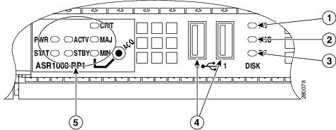
The Cisco ASR 1000 Series route processor (RP1) contains an internal hard drive disk that provides nonvolatile storage in the form of an internal flash disk. The Cisco ASR 1000 Series RP1 module can be configured with either a 40 GB or a 32 GB disk. Both components are field-replaceable on the Cisco ASR 1006 Router and the Cisco ASR 1004 Router (there is no hard disk in the Cisco ASR 1002 Router). On the front panel of the Cisco ASR 1000 Series RP, the DISK HD LED indicates activity on the hard drive.

This section explains how to remove a hard drive assembly from the Cisco ASR1000-RP1 module and replace it with a new internal hard drive.

Removing the Cisco ASR1000-RP1 Internal Hard Drive

To remove the Cisco ASR1000-RP1 from the Cisco ASR 1000 Series Router, follow this procedure:

SUMMARY STEPS

  1. Slip on the ESD-preventive wrist strap that was included in the accessory kit. Loosen the screw fasteners on the Cisco ASR 1000 Series RP1 module.
  2. Using the handles on both sides of the module, with two hands gently slide the Cisco ASR1000-RP1 out of the chassis.
  3. Place the module on a flat surface free of dust and dirt.
  4. Remove the internal hard drive cover:
  5. Remove the internal drive cover:
  6. Inspect the existing cables and replace them only if they are damaged. If you do not need to replace them, leave the connection to the Cisco ASR 1000 Series Route Processor 1 in place and only remove the connection to the internal hard drive.
  7. Carefully disconnect the cables at the rear of the hard drive. These cables are tie-wrapped in to prevent them from disconnecting from the Cisco ASR 1000 Series RP1 itself. If the cables are not damaged, leave the cables connected to the Cisco ASR 1000 Series RP1 with the tie wrap in place. Remove the old hard drive.
  8. If the cables are damaged:

DETAILED STEPS


Step 1

Slip on the ESD-preventive wrist strap that was included in the accessory kit. Loosen the screw fasteners on the Cisco ASR 1000 Series RP1 module.

Step 2

Using the handles on both sides of the module, with two hands gently slide the Cisco ASR1000-RP1 out of the chassis.

Step 3

Place the module on a flat surface free of dust and dirt.

Step 4

Remove the internal hard drive cover:

  1. Unscrew the fasteners.
  2. Slide the cover off.
  3. Lift the cover up from the board.

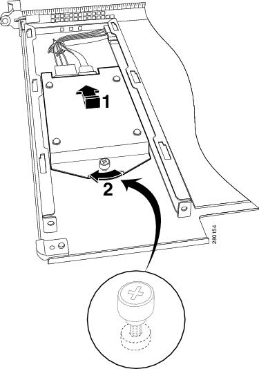
The following figure shows the Cisco ASR1000RP1 module internal hard drive unit.

Figure 1. Cisco ASR1000RP1 Module Internal Hard Drive Unit

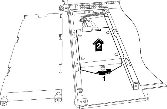
The following figure shows the Cisco ASR1000-RP1 module with the hard drive cover removed.

Figure 2. Cisco ASR1000-RP1 Module Hard Drive Cover and Screw Fastener
Step 5

Remove the internal drive cover:

  1. Using a # 2 Phillips screwdriver or a flat head screwdriver, loosen the screw fasteners on the cover.

  2. Slide the cover off as shown in xref Figure 14-2.

  3. Lift the cover up from the board.

Step 6

Inspect the existing cables and replace them only if they are damaged. If you do not need to replace them, leave the connection to the Cisco ASR 1000 Series Route Processor 1 in place and only remove the connection to the internal hard drive.

Step 7

Carefully disconnect the cables at the rear of the hard drive. These cables are tie-wrapped in to prevent them from disconnecting from the Cisco ASR 1000 Series RP1 itself. If the cables are not damaged, leave the cables connected to the Cisco ASR 1000 Series RP1 with the tie wrap in place. Remove the old hard drive.

The following figure shows the cables still connected because they do not have to be replaced.

Figure 3. Cisco ASR1000-RP1 Module With Internal Hard Drive Removed
Step 8

If the cables are damaged:

  1. Remove the tie wrap around the cables.

  2. Disconnect the cables from both the Cisco ASR 1000 Series Route Processor 1 connector and the internal hard drive connector as shown in the following figure.

    Figure 4. Cisco ASR1000-RP1 Module Internal Hard Drive and Module Base

    This completes the procedure for disconnecting the Cisco ASR 1000 Series RP internal hard drive.


Replacing the Cisco ASR1000-RP1 Internal Hard Drive

To replace the Cisco ASR1000-RP1 internal hard drive and insert the Cisco ASR 1000 Series Route Processor 1 into the Cisco ASR 1000 Series Router, follow these steps:

SUMMARY STEPS

  1. On the Cisco ASR1000-RP1, carefully align the new hard drive unit with its screw fastener to the base screw on the bottom of the module.
  2. Reconnect the two cables to the rear of the hard drive. These are keyed for easy connection.
  3. Align hard drive module to carrier base tabs, align the module fastener to base screw mate by hand, and then tighten with screw driver.
  4. Replace the cover by aligning the tabs in the slot and tightening the screw fasteners.
  5. With two hands, grab the handles on the Cisco ASR1000-RP1 module and slide it back into its slot in the Cisco ASR 1000 Series Router and tighten the captive screw.

DETAILED STEPS


Step 1

On the Cisco ASR1000-RP1, carefully align the new hard drive unit with its screw fastener to the base screw on the bottom of the module.

Step 2

Reconnect the two cables to the rear of the hard drive. These are keyed for easy connection.

The following figure shows the Cisco ASR1000-RP1 module internal hard drive and module base.

Figure 5. Cisco ASR1000-RP1 Module Internal Hard Drive and Module Base

1

Hard drive module fastener

2

Carrier mating fastener

Step 3

Align hard drive module to carrier base tabs, align the module fastener to base screw mate by hand, and then tighten with screw driver.

Step 4

Replace the cover by aligning the tabs in the slot and tightening the screw fasteners.

Step 5

With two hands, grab the handles on the Cisco ASR1000-RP1 module and slide it back into its slot in the Cisco ASR 1000 Series Router and tighten the captive screw.


Removing and Replacing the Cisco ASR1000-RP2 Module Internal Hard Drive

This section explains how to remove a hard drive assembly from the Cisco ASR 1000 Series RP2 module and replace it with a new internal hard drive.


Warning

During this procedure, wear grounding wrist straps to avoid ESD damage to the card. Do not directly touch the backplane with your hand or any metal tool, or you could shock yourself. Statement 94


Before you begin, read the following important notices:

  • The form-factor internal hard drive is accessible from the front panel of the Cisco ASR1000-RP2 and supports the online insertion and removal feature (OIR) using the following CLI commands for the standby and active RP2:
    • request platform hardware filesystem harddisk: offline (Unmounts the hard disk on the active RP2.)
    • request platform hardware filesystem harddisk: online (Mounts the hard disk on the active RP2.) If the disk is not provisioned properly, this command will provision the disk.
    • request platform hardware filesystem stby-harddisk: offline (Unmounts the hard disk on the standby RP2.)
    • request platform hardware filesystem stby-harddisk: online (Mounts the hard disk on the standby RP2. If the disk is not provisioned properly, this command will provision the disk.)
  • The reason you would be removing an internal hard drive is that it is failing or failed; so any data recovery may be lost.
  • If the drive is functioning, you can back it up to a drive plugged into a USB port using the archive tar command.

Removing the Cisco ASR1000-RP2 Internal Hard Drive

To remove the Cisco ASR1000-RP2 internal hard drive from the Cisco ASR 1006 Router and Cisco ASR 1004 Router, follow this procedure:

SUMMARY STEPS

  1. Run the request platform hardware filesystem harddisk: offline command.
  2. Slip on an ESD-preventive wrist strap.
  3. From the front panel of the Cisco ASR1000-RP2, unscrew the fastener screw (see the following figure).
  4. Pull the internal hard drive out as shown in the following figure.
  5. Place the component in an antistatic bag if you are returning it.
  6. Wait until the following console message is displayed:

DETAILED STEPS


Step 1

Run the request platform hardware filesystem harddisk: offline command.

Step 2

Slip on an ESD-preventive wrist strap.

Step 3

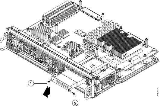
From the front panel of the Cisco ASR1000-RP2, unscrew the fastener screw (see the following figure).

Figure 6. Cisco ASR1000-RP2 Front Panel

1

Internal hard drive fastener screw

2

Internal hard drive

Step 4

Pull the internal hard drive out as shown in the following figure.

Figure 7. Cisco ASR1000-RP2 Internal Hard Drive

1

Internal hard drive fastener screw location

2

Internal hard drive

Step 5

Place the component in an antistatic bag if you are returning it.

Step 6

Wait until the following console message is displayed:

Example:

%IOSXE-0-PLATFORM: R0/0: udev: harddisk: has been removed

What to do next

You have successfully removed the Cisco ASR1000-RP2 hard drive.

Replacing the Cisco ASR1000-RP2 Internal Hard Drive

To replace the Cisco ASR1000-RP2 internal hard drive and insert the Cisco ASR1000-RP 2 into the Cisco ASR 1000 Series Router, follow these steps:

SUMMARY STEPS

  1. Carefully slide the internal hard drive unit into the Cisco ASR1000-RP2 faceplate slot. The component is keyed for easy insertion.
  2. Tighten the fastener screw on the front panel.
  3. Wait until the following console message is displayed:
  4. Verify the disk is working by running: dir harddisk

DETAILED STEPS


Step 1

Carefully slide the internal hard drive unit into the Cisco ASR1000-RP2 faceplate slot. The component is keyed for easy insertion.

Step 2

Tighten the fastener screw on the front panel.

Step 3

Wait until the following console message is displayed:

Example:

%IOSXE-0-PLATFORM: R0/0: udev: harddisk: file system ready” appears. 

If, after several minutes, the above message is not displayed, run:

request platform hardware filesystem harddisk: online

Note 
The only reason the system would not be able to automatically mount the new hard disk following a physical insertion is if the disk is not partitioned correctly.
Step 4

Verify the disk is working by running: dir harddisk


What to do next

You have completed the steps required to replace the Cisco ASR1000-RP2 internal hard drive.

Removing and Replacing the Hard Drive on the Cisco ASR 1002-X Router

The Cisco ASR 1002-X Router supports an optional removable hard drive. This section explains how to remove and replace this hard drive.


Warning

During this procedure, wear grounding wrist straps to avoid ESD damage to the card. Do not directly touch the backplane with your hand or any metal tool, or you could shock yourself. Statement 94


Before you begin, read the following important notices:

  • The hard drive is accessible from the front panel of the router and supports the online insertion and removal feature (OIR) using the following CLI commands:
    • request platform hardware filesystem harddisk: offline (unmounts the hard disk)
    • request platform hardware filesystem harddisk: online (mounts the hard disk.)
  • The reason you may be removing an internal hard drive is that it is failing or failed; so any data recovery may be lost.
  • If the drive is functioning, you can back it up to a drive plugged into a USB port using the archive tar command.

Removing the Hard Drive from the Cisco ASR 1002-X Router

To remove the hard drive from the Cisco ASR 1002-X Router, follow this procedure:

SUMMARY STEPS

  1. Run the request platform hardware filesystem harddisk: offline command.
  2. Slip on an ESD-preventive wrist strap.
  3. From the front panel of the router, unscrew the fastener screws by using a # 2 Phillips screwdriver or a flat head screwdriver (see xref Figure 14-6).
  4. Pull the hard drive out as shown in xref Figure 14-7.
  5. Place the hard drive in an antistatic bag if you are returning it.
  6. Wait until the following console message is displayed:

DETAILED STEPS


Step 1

Run the request platform hardware filesystem harddisk: offline command.

Step 2

Slip on an ESD-preventive wrist strap.

Step 3

From the front panel of the router, unscrew the fastener screws by using a # 2 Phillips screwdriver or a flat head screwdriver (see xref Figure 14-6).

Figure 8. Cisco ASR1002-X Router Front Panel

1

Internal hard drive fastener screw

2

Internal hard drive

Step 4

Pull the hard drive out as shown in xref Figure 14-7.

Figure 9. Cisco ASR1002-X Router Hard Drive

1

Hard drive fastener screw location

2

Hard drive

Step 5

Place the hard drive in an antistatic bag if you are returning it.

Step 6

Wait until the following console message is displayed:

Example:


%IOSXE-0-PLATFORM: R0/0: udev: harddisk: has been removed

What to do next

You have successfully removed the hard drive from the Cisco ASR 1002-X Router.

Replacing the Hard Drive on the Cisco ASR 1002-X Router

To insert or replace the hard drive on the Cisco ASR 1002-X Router, follow this procedure:

SUMMARY STEPS

  1. Carefully slide the hard drive unit into the slot on the front panel. The component is keyed for easy insertion.
  2. Tighten the fastener screw on the front panel by using a # 2 Phillips screwdriver or a flat head screwdriver.
  3. Wait until the following console message is displayed:
  4. Verify that the hard drive is working by running the following command:

DETAILED STEPS


Step 1

Carefully slide the hard drive unit into the slot on the front panel. The component is keyed for easy insertion.

Step 2

Tighten the fastener screw on the front panel by using a # 2 Phillips screwdriver or a flat head screwdriver.

Step 3

Wait until the following console message is displayed:

Example:


%IOSXE-0-PLATFORM: R0/0: udev: harddisk: file system ready” appears. 

If this message is not displayed after a few minutes, run the following command:

request platform hardware filesystem harddisk: online

Note 
If the new hard drive system does not get mounted automatically, the disk may not be partitioned correctly.
Step 4

Verify that the hard drive is working by running the following command:

dir harddisk


What to do next

You have successfully replaced the hard drive on the Cisco ASR 1002-X Router.

Removing and Replacing the Hard Drive on the Cisco ASR 1001 Router

The Cisco ASR 1001 Router supports an optional removable hard drive. This section explains how to remove and replace this hard drive.


Warning

During this procedure, wear grounding wrist straps to avoid ESD damage to the card. Do not directly touch the backplane with your hand or any metal tool, or you could shock yourself. Statement 94


Before you begin, read the following important notices:

  • The hard drive is accessible from the front panel of the router and supports the online insertion and removal feature (OIR) using the following CLI commands:
    • request platform hardware filesystem harddisk: offline (unmounts the hard disk)
    • request platform hardware filesystem harddisk: online (mounts the hard disk.)
  • The reason you may be removing an internal hard drive is that it is failing or failed; so any data recovery may be lost.
  • If the drive is functioning, you can back it up to a drive plugged into a USB port using the archive tar command.

Removing the Hard Drive from the Cisco ASR 1001 Router

To remove the hard drive from the Cisco ASR 1001 Router, follow this procedure:

SUMMARY STEPS

  1. Run the request platform hardware filesystem harddisk: offline command.
  2. Slip on an ESD-preventive wrist strap.
  3. From the front panel of the router, unscrew the fastener screws by using a # 2 Phillips screwdriver or a flat head screwdriver (see xref Figure 14-6).
  4. Pull the hard drive out as shown in xref Figure 14-7.
  5. Place the hard drive in an antistatic bag if you are returning it.
  6. Wait until the following console message is displayed:

DETAILED STEPS


Step 1

Run the request platform hardware filesystem harddisk: offline command.

Step 2

Slip on an ESD-preventive wrist strap.

Step 3

From the front panel of the router, unscrew the fastener screws by using a # 2 Phillips screwdriver or a flat head screwdriver (see xref Figure 14-6).

Figure 10. Cisco ASR1001 Router Front Panel

1

Internal hard drive fastener screw

2

Internal hard drive

Step 4

Pull the hard drive out as shown in xref Figure 14-7.

Figure 11. Cisco ASR1001 Router Hard Drive

1

Hard drive fastener screw location

2

Hard drive

Step 5

Place the hard drive in an antistatic bag if you are returning it.

Step 6

Wait until the following console message is displayed:

Example:


%IOSXE-0-PLATFORM: R0/0: udev: harddisk: has been removed

What to do next

You have successfully removed the hard drive from the Cisco ASR 1001 Router.

Replacing the Hard Drive on the Cisco ASR 1001 Router

To insert or replace the hard drive on the Cisco ASR 1001 Router, follow this procedure:

SUMMARY STEPS

  1. Carefully slide the hard drive unit into the slot on the front panel. The component is keyed for easy insertion.
  2. Tighten the fastener screw on the front panel by using a # 2 Phillips screwdriver or a flat head screwdriver.
  3. Wait until the following console message is displayed:
  4. Verify that the hard drive is working by running the following command:

DETAILED STEPS


Step 1

Carefully slide the hard drive unit into the slot on the front panel. The component is keyed for easy insertion.

Step 2

Tighten the fastener screw on the front panel by using a # 2 Phillips screwdriver or a flat head screwdriver.

Step 3

Wait until the following console message is displayed:

Example:


%IOSXE-0-PLATFORM: R0/0: udev: harddisk: file system ready” appears. 

If this message is not displayed after a few minutes, run the following command:

request platform hardware filesystem harddisk: online

Note 
If the new hard drive system does not get mounted automatically, the disk may not be partitioned correctly.
Step 4

Verify that the hard drive is working by running the following command:

dir harddisk


What to do next

You have successfully replaced the hard drive on the Cisco ASR 1001 Router.

Removing and Replacing the Cisco ASR 1000 Series DIMM Memory Modules

Cisco ASR 1000 Series Routers support the Cisco ASR1000-RP1 and the Cisco ASR1000-RP2 route processor DIMM memory modules for system DRAM. This section describes how to replace the DIMMs on the Cisco ASR1000-RP1, the Cisco ASR1000-RP2 route processors, the Cisco ASR 1001, and the Cisco ASR 1002-X routers.

The following table shows the Cisco ASR1000-RP1 and Cisco ASR1000-RP2 memory design.

Table 1. Cisco ASR 1000 Series Route Processor Memory Support

Cisco ASR1000-RP1

Cisco ASR1000-RP2

Supports up to 4 GB memory

Supports up to 16 GB memory

  • 1 GB (2 GB) miniDIMMs
  • 4 GB dual rank VLP DIMMs
  • DDR-533
  • Up to 4 DIMMs with up to two DIMMs per channel

  • Allowable memory options of 4 GB, 8 GB, or 16 GB

  • DDR-667

You might need to upgrade the DIMM for the following reasons:

  • You have upgraded to a new Cisco IOS feature set or release that requires more memory.
  • You are using very large routing tables or many protocols.

This section contains the following topics:

Removing and Replacing the DIMM Memory Modules on the Cisco ASR 1006 Router and the Cisco ASR 1013 Router

The Cisco ASR 1006 Router and the Cisco ASR 1013 Router have redundant RPs. The following is an overview of the steps to remove and replace the DIMM memory modules on these routers:

SUMMARY STEPS

  1. Remove the standby RP by performing the procedure described in the xref “Removing the Cisco ASR 1000 Series Route Processor from the Cisco ASR 1006, Cisco ASR 1004, and Cisco ASR 1013 Routers” section.
  2. Remove the DIMM memory module from the standby RP by performing one of the following procedures:
    • Removing and Replacing the Cisco ASR1000-RP1 DIMM Memory Modules

      Removing the Cisco ASR1000-RP2 DIMMs

  3. Insert the new DIMM memory module on the standby RP by performing one of the following procedures:
    • Removing and Replacing the Cisco ASR1000-RP1 DIMM Memory Modules

      Removing the Cisco ASR1000-RP2 DIMMs

  4. Insert the standby RP by performing the procedure described in the xref “Removing the Cisco ASR 1000 Series Route Processor from the Cisco ASR 1006, Cisco ASR 1004, and Cisco ASR 1013 Routers” section.
  5. Verify the memory upgrade on the standby RP by running the following commands:
  6. Use the redundancy force-switchover command to switch the upgraded standby RP to the active state. The RP that was in the active state moves to the standby state.
  7. Repeat Step 1 through Step 5 on the standby RP.

DETAILED STEPS


Step 1

Remove the standby RP by performing the procedure described in the xref “Removing the Cisco ASR 1000 Series Route Processor from the Cisco ASR 1006, Cisco ASR 1004, and Cisco ASR 1013 Routers” section.

Step 2

Remove the DIMM memory module from the standby RP by performing one of the following procedures:

  • Removing and Replacing the Cisco ASR1000-RP1 DIMM Memory Modules

    Removing the Cisco ASR1000-RP2 DIMMs

Step 3

Insert the new DIMM memory module on the standby RP by performing one of the following procedures:

  • Removing and Replacing the Cisco ASR1000-RP1 DIMM Memory Modules

    Removing the Cisco ASR1000-RP2 DIMMs

Step 4

Insert the standby RP by performing the procedure described in the xref “Removing the Cisco ASR 1000 Series Route Processor from the Cisco ASR 1006, Cisco ASR 1004, and Cisco ASR 1013 Routers” section.

Step 5

Verify the memory upgrade on the standby RP by running the following commands:

Example:


Router# configure terminal
Router(config-red)# redundancy
Router(config-r-mc)# main-cpu
Router(config-r-mc)# standby console enable
Router(config-r-mc)# end
Router-stby# show version
Cisco IOS Software, IOS-XE Software (PPC_LINUX_IOSD-ADVENTERPRISEK9-M), Experimental Version 15.2(20111220:221816) [v152_2_s_xe36_throttle-tozhang-xe36_ios 114]
.
.
.
cisco ASR1006 (RP1) processor with 1689519K/6147K bytes of memory.
Processor board ID FOX1224G4VX
20 Gigabit Ethernet interfaces
32768K bytes of non-volatile configuration memory.
4194304K bytes of physical memory.
955063K bytes of eUSB flash at bootflash:.
39004543K bytes of SATA hard disk at harddisk:.
.
.
.
Step 6

Use the redundancy force-switchover command to switch the upgraded standby RP to the active state. The RP that was in the active state moves to the standby state.

Step 7

Repeat Step 1 through Step 5 on the standby RP.


Removing and Replacing the Cisco ASR1000-RP1 DIMM Memory Modules

The Cisco ASR1000-RP1 module memory interface supports two DDR-II SDRAM MiniDIMMs with ECC protection.


Note

Unlike the Cisco ASR 1006, ASR 1004, and ASR 1013 routers, the DIMM memory interface is not field-replaceable on the Cisco ASR 1002 router.

This section provides instructions for removing and replacing the Cisco ASR1000-RP1 Mini DIMM memory modules.


Note

The Cisco ASR 1000 Series RP memory spares are sold as pairs. For example, the 2 GB memory spare (M-ASR1K-RP1-2GB=) is sold as a pair of 1 GB modules and the 4 GB memory spare (M-ASR1K-RP1-4GB=) is sold as a pair of 2 GB modules. Memory repairs or upgrades must utilize the complete memory pairs as shipped from Cisco. For example, if 1 of the 2 memory modules were to fail on the Cisco ASR 1000route processor, then both memory modules must be removed and replaced with a spare memory pair (as shipped from Cisco) and the failing memory should be returned as a pair to Cisco.To prevent the system from operating incorrectly, do not mix modules from different vendors. The modules might not be compatible with each other.

Warning

During these procedures, wear grounding wrist straps to avoid ESD damage to the card. Do not directly touch the backplane with your hand or any metal tool, or you could shock yourself. Statement 94


The following table shows the slots that are supported for inserting memory DIMMs in Cisco ASR1000-RP1

Table 2. Cisco ASR1000-RP1 Supported Slots for Inserting Memory DIMMs

Memory PID Option

Slot 0

Slot 1

M-ASR1K-RP1-4GB=

2 GB module

2 GB module

M-ASR1K-RP1-2GB=

1 GB module

1GB module

Perform the following steps before you begin:

  • Use an ESD-preventive wrist strap
  • Back up data before replacing a eUSB device.
  • The card is keyed and slotted for easier connection.
  • Never wiggle the DIMM.
  • Handle the connector according to the instructions (see xref Figure 14-15).

To replace or upgrade the Cisco ASR1000-RP1 DIMM memory spare, follow these steps:

SUMMARY STEPS

  1. Attach an ESD-preventive wrist strap between you and an unpainted router surface.
  2. Locate the DIMM on the system board.
  3. Press both spring latches outward to release the DIMM.
  4. Pull the latches away from the DIMM on both edges. This lifts the DIMM slightly. Gently lift the DIMM free from the DIMM connector, taking care not to touch the pins that insert into the socket.
  5. Place the DIMM in an antistatic bag to protect the DIMM from ESD damage.
  6. To install the DIMM memory card, locate the notches and align the DIMM with the socket before inserting it.
  7. Make certain that both latches on the DIMM connector are open.
  8. Gently insert the new DIMM, taking care not to damage the pins on the edge of the DIMM.Using two hands, place the index fingers on the edge of the DIMM and place the thumbs on the socket, being careful not to touch the socket pins. Press on the back of the DIMM towards the socket by squeezing the index fingers and the thumbs together, being careful to only apply force onto the DIMM parallel with the plane of the DIMM.
  9. To allow the DIMM to slide into the socket smoothly with minimum force, one can alternate applying force back and forth between the left hand and the right hand, allowing one side to engage prior to the other. Carefully and firmly press the DIMM into the connector until the spring latches lock the DIMM in place. See Figure 14-12.
  10. Slide the DIMM one side at a time. Use light insertion force and insert smoothly; but make certain the DIMM is inserted straight .

DETAILED STEPS


Step 1

Attach an ESD-preventive wrist strap between you and an unpainted router surface.

Step 2

Locate the DIMM on the system board.

Note 
The DIMMs shown in xref Figure 14-12 and Figure 14-13 are representative and might not look exactly like the DIMMs used on the RP; but the procedure is the same.
Step 3

Press both spring latches outward to release the DIMM.

The following figure shows the Cisco ASR 1000 Series RP DIMM module spring latches.

Figure 12. Cisco ASR 1000 Series RP DIMM Module Spring Latches

insert callout table

1 - Pull spring clips outward.

2 - Pull DIMM out.

Step 4

Pull the latches away from the DIMM on both edges. This lifts the DIMM slightly. Gently lift the DIMM free from the DIMM connector, taking care not to touch the pins that insert into the socket.

Step 5

Place the DIMM in an antistatic bag to protect the DIMM from ESD damage.

Caution 

Forcing the DIMM into the socket can damage the DIMM. Use the notches on the DIMM to align the DIMM in the DIMM socket before inserting it (see the following figure).

Figure 13. Cisco ASR 1000 Series RP DIMM Module Notch Location
Step 6

To install the DIMM memory card, locate the notches and align the DIMM with the socket before inserting it.

The following figure shows the Cisco ASR 1000 Series RP DIMM module alignment.

Figure 14. Cisco ASR 1000 Series RP DIMM Module Alignment
Note 
Hold the DIMM with two hands at its edge and insert the card.
Step 7

Make certain that both latches on the DIMM connector are open.

Step 8

Gently insert the new DIMM, taking care not to damage the pins on the edge of the DIMM.Using two hands, place the index fingers on the edge of the DIMM and place the thumbs on the socket, being careful not to touch the socket pins. Press on the back of the DIMM towards the socket by squeezing the index fingers and the thumbs together, being careful to only apply force onto the DIMM parallel with the plane of the DIMM.

Step 9

To allow the DIMM to slide into the socket smoothly with minimum force, one can alternate applying force back and forth between the left hand and the right hand, allowing one side to engage prior to the other. Carefully and firmly press the DIMM into the connector until the spring latches lock the DIMM in place. See Figure 14-12.

Caution 

Strong insertion force introduces excessive mechanical stress on the DIMM. To prevent any stress on the soldering joints, there should be no up, down, or wiggling motion to be done on the DIMM during the insertion. Forcing the DIMM into the socket can damage the DIMM. Check that the notches on the DIMM are properly aligned with the ones on the connector before fully inserting the DIMM.

The following figure shows how the Cisco ASR 1000 Series RP DIMM module must not be handled.

Figure 15. Handling Cisco ASR 1000 Series RP DIMM Module
Step 10

Slide the DIMM one side at a time. Use light insertion force and insert smoothly; but make certain the DIMM is inserted straight .

Note 
Make sure you perform steps 3 thru 11 for both DIMMs on the RP 1 before you replace the Cisco ASR1000-RP1 in the system. Replace the Cisco ASR1000-RP1. All DIMMS must be replaced; not just one.

What to do next

This completes the procedure for replacing a DIMM memory module on the Cisco ASR1000-RP1.

Removing and Replacing the Cisco ASR1000-RP2 DIMM Memory Modules

Perform the following steps before you begin:

  • Use an ESD-preventive wrist strap.
  • Back up data that you want to save before replacing a eUSB device.
  • Note that the component is keyed and slotted for easier connection.
  • To ensure the DIMMs are functioning properly, all four DIMMs must be replaced at the same time and must be of the same manufacturer and part number (since vendors may have multiple versions of the DIMM).

The following table shows the slots that are supported for inserting memory DIMMs in Cisco ASR1000-RP2

Table 3. Cisco ASR1000-RP2 Supported Slots for Inserting Memory DIMMs

Memory PID Option

Slot 0

Slot 1

Slot 2

Slot 3

M-ASR1K-RP2-8GB=

2 GB module

2 GB module

2 GB module

2 GB module

M-ASR1K-RP2-16GB=

4 GB Module

4 GB Module

4 GB Module

4 GB Module

This section describes how to remove and then replace the Cisco ASR1000-RP2 module DIMMs (see the following figure).

Figure 16. Cisco ASR1000-RP2 Module Internal Component Location

1

Internal hard drive location

3

Cisco ASR1000-RP2 internal eUSB device

2

Cisco ASR1000-RP2 DIMM location

Removing the Cisco ASR1000-RP2 DIMMs

Follow these steps to remove the Cisco ASR1000-RP2 DIMMs:

SUMMARY STEPS

  1. With a wrist strap on, loosen the two captive screws on the faceplate of the Cisco ASR 1000 Series RP.
  2. Using the handles on both sides of the module, with two hands gently slide the module out of the chassis slot.
  3. Place the route processor on an antistatic mat or pad and ensure that you are wearing an antistatic device, such as a wrist strap.
  4. Position the route processor so that the faceplate is toward you and the edge connector is away from you.
  5. Locate the DIMMs on the ASR1000-RP2. See xref Figure 14-16, callout 2.
  6. For the DIMM you want to remove, pull down the lever on the DIMM socket to release the DIMM from the socket. See the following figure.
  7. When one end of the DIMM is released from the socket, grasp each end of the DIMM with your thumb and forefinger and pull the DIMM completely out of the socket. Handle the edges of the DIMM only; avoid touching the memory module or pins and the metal traces (the metal fingers along the connector edge of the DIMM) along the socket edge.
  8. Place the DIMM in an antistatic bag to protect it from ESD damage.
  9. Repeat Step 5 through Step 8 for the remaining DIMMs if required for your upgrade.

DETAILED STEPS


Step 1

With a wrist strap on, loosen the two captive screws on the faceplate of the Cisco ASR 1000 Series RP.

Step 2

Using the handles on both sides of the module, with two hands gently slide the module out of the chassis slot.

Step 3

Place the route processor on an antistatic mat or pad and ensure that you are wearing an antistatic device, such as a wrist strap.

Step 4

Position the route processor so that the faceplate is toward you and the edge connector is away from you.

Step 5

Locate the DIMMs on the ASR1000-RP2. See xref Figure 14-16, callout 2.

Step 6

For the DIMM you want to remove, pull down the lever on the DIMM socket to release the DIMM from the socket. See the following figure.

Figure 17. DIMM Socket Release Lever to Remove the DIMM
Step 7

When one end of the DIMM is released from the socket, grasp each end of the DIMM with your thumb and forefinger and pull the DIMM completely out of the socket. Handle the edges of the DIMM only; avoid touching the memory module or pins and the metal traces (the metal fingers along the connector edge of the DIMM) along the socket edge.

Step 8

Place the DIMM in an antistatic bag to protect it from ESD damage.

Step 9

Repeat Step 5 through Step 8 for the remaining DIMMs if required for your upgrade.


What to do next

This completes the steps for removing the Cisco ASR1000-RP2 DIMMs from the module.

Replacing the Cisco ASR1000-RP2 DIMMs

This section lists the steps to replace the Cisco ASR1000-RP2 DIMMs.

SUMMARY STEPS

  1. Place the route processor on an antistatic mat or pad and ensure that you are wearing an antistatic device, such as a wrist strap.
  2. Position the route processor so that the faceplate is toward you and the edge connector is away from you.
  3. Remove the new DIMM from the antistatic bag.
  4. Hold the DIMM component-side up, with the connector edge (the metal fingers) closest to you. Hold the ends of the DIMM between your thumb and forefinger. See the following figure.
  5. Tilt the DIMM to approximately the same angle as the socket and insert the connector edge into the socket. Note the two notches (keys) on the connector edge of the DIMM. These keys are intended to ensure correct orientation of the DIMM in the socket.
  6. Note the orientation of the socket key on the DIMM and the DIMM socket and gently push the DIMM into the socket until the lever is flush against the side of the DIMM socket, and the DIMM edge connector is fully inserted. If necessary, rock the DIMM gently back and forth to seat it properly. The following figure shows how to install the DIMM in the socket.
  7. When the DIMM is installed, check that the release lever is flush against the side of the DIMM socket. If it is not, the DIMM might not be seated properly. If the DIMM appears misaligned, carefully remove it according to the removal procedure and then reseat it in the socket. Push the DIMM firmly back into the socket until the release lever is flush against the side of the DIMM socket.
  8. Repeat Step 3 through Step 7 for the remaining DIMMs.
  9. Replace the Cisco ASR1000-RP2.

DETAILED STEPS


Step 1

Place the route processor on an antistatic mat or pad and ensure that you are wearing an antistatic device, such as a wrist strap.

Step 2

Position the route processor so that the faceplate is toward you and the edge connector is away from you.

Caution 

DIMMs are sensitive components that can be shorted by mishandling; they are susceptible to ESD damage. Handle DIMMs by the edges only and avoid touching the pins.

Step 3

Remove the new DIMM from the antistatic bag.

Step 4

Hold the DIMM component-side up, with the connector edge (the metal fingers) closest to you. Hold the ends of the DIMM between your thumb and forefinger. See the following figure.

Figure 18. Handling the Cisco ASR1000-RP2 DIMM
Step 5

Tilt the DIMM to approximately the same angle as the socket and insert the connector edge into the socket. Note the two notches (keys) on the connector edge of the DIMM. These keys are intended to ensure correct orientation of the DIMM in the socket.

Caution 

When inserting DIMMs, use firm but not excessive pressure. If you damage a socket, you will have to return the route processor to the factory for repair.

Step 6

Note the orientation of the socket key on the DIMM and the DIMM socket and gently push the DIMM into the socket until the lever is flush against the side of the DIMM socket, and the DIMM edge connector is fully inserted. If necessary, rock the DIMM gently back and forth to seat it properly. The following figure shows how to install the DIMM in the socket.

Figure 19. Installing the DIMM in the Socket
Step 7

When the DIMM is installed, check that the release lever is flush against the side of the DIMM socket. If it is not, the DIMM might not be seated properly. If the DIMM appears misaligned, carefully remove it according to the removal procedure and then reseat it in the socket. Push the DIMM firmly back into the socket until the release lever is flush against the side of the DIMM socket.

Step 8

Repeat Step 3 through Step 7 for the remaining DIMMs.

Step 9

Replace the Cisco ASR1000-RP2.


What to do next

This completes the procedure for replacing Cisco ASR1000-RP2 DIMMs.

After you have correctly installed the Cisco ASR1000-RP2 DIMMs and reinstalled the route processor, the system should reboot properly.

If the system fails to boot properly or if the console terminal displays a checksum or memory error after you have installed new DIMMs, check the following:

  • Ensure that all DIMMs are installed correctly. If necessary, shut down the system and remove the route processor. Check the DIMMs by looking straight down on them to inspect them at eye level. The DIMMs should all be aligned at the same angle and the same height when properly installed. If a DIMM appears to stick out or rest in the socket at a different angle from the others, remove the DIMM and reinsert it. Then replace the route processor and reboot the system for another installation check.
  • Make certain that all DIMMs are of the same manufacturer and part number.

Note

If after several attempts the system fails to restart properly, contact a service representative for assistance. Before you call, make note of any error messages, unusual LED states, or any other indications that might help solve the problem.

Removing and Replacing the Cisco ASR 1001 Router DIMM Memory Modules

Perform the following steps before you begin:

  • Use an ESD-preventive wrist strap.
  • Back up data that you want to save.
  • Remove the power supplies before you remove the chassis top cover.

Caution

The top cover cannot be removed until the power supplies are removed from the chassis. The chassis has a safety mechanism built in to prevent the removal of the top cover until the power supplies are removed.


  • The DIMM component is keyed and slotted for easier connection.
  • The Cisco ASR 1001 Router has four DIMM slots.

Warning

Do not install power supplies with the Cisco ASR 1001 chassis cover off.


The following table shows the slots that are supported for inserting memory DIMMs in the Cisco ASR1001 Router.

Table 4. Cisco ASR1001 Router Supported Slots for Inserting Memory DIMMs

Memory PID Option

Slot 0 (U101D)

Slot 1 (U103D)

Slot 2 (U100D)

Slot 3 (U102D)

M-ASR1K-1001-4GB

2 GB module

2 GB module

M-ASR1K-1001-8GB

2 GB Module

2 GB Module

2 GB Module

2 GB Module

M-ASR1K-1001-16GB

4 GB Module

4 GB Module

4 GB Module

4 GB Module


Note

Ensure that the vendor and manufacturing part number (MPN) for all DIMMs are the same.

Note

When upgrading memory from 4 GB to 8 GM, remove all existing memory DIMMS in the Cisco ASR 1001 Router, and then populate the DIMM Slots with the new 8 GB memory upgrade kit.

This section describes how to remove the chassis cover and then remove and replace the Cisco ASR 1001 Router DIMM. The following figure shows the location of the DIMM and eUSB in the Cisco ASR 1001 Router.

Figure 20. Cisco ASR 1001 Router Internal Component Location

1

Cisco ASR 1001 Router DIMM location (four slots)

2

Cisco ASR 1001 Router eUSB location

Removing the Cisco ASR 1001 Router DIMMs

Follow these steps to remove the Cisco ASR 1001 Router DIMM:

SUMMARY STEPS

  1. With a wrist strap on, remove the power supplies from the chassis.
  2. After the power supplies are removed, remove the chassis top cover by performing the following steps:
  3. Position the chassis so that you are facing the front of the chassis to remove the DIMM.
  4. Locate the DIMM on the ASR 1001 Router. See Figure 14-20, callout 1.
  5. Pull down the lever on the DIMM socket to release the corresponding DIMM from the socket. See the following figure.
  6. When one end of the DIMM is released from the socket, grasp each end of the DIMM with your thumb and forefinger and pull the DIMM completely out of the socket. Handle only the edges of the DIMM; avoid touching the memory module, pins, and the metal traces (the metal fingers along the connector edge of the DIMM) along the socket edge.
  7. Place the DIMM in an antistatic bag to protect it from ESD damage.
  8. Repeat Step 8 through Step 10 for the remaining DIMMs if required for your upgrade.

DETAILED STEPS


Step 1

With a wrist strap on, remove the power supplies from the chassis.

Note 
The chassis cover cannot be removed until the power supplies are removed from the chassis.

For instructions about how to remove the AC and DC power supplies from the Cisco ASR 1001 Router, see:

xref Removing AC Power Supply from the Cisco ASR 1001 Router

xref Removing DC Input Power from the Cisco ASR 1001 Router

Step 2

After the power supplies are removed, remove the chassis top cover by performing the following steps:

  1. Loosen all top surface screws on the chassis cover, as shown in the following figure, callout 3.

  2. Loosen the three screws on the faceplate at the front of the chassis, as shown in the following figure, callout 6.

    Figure 21. Removing the Cisco ASR 1001 Router Cover

    1

    Interlock pin safety feature

    4

    Interlock hook feature on the chassis cover and base

    2

    Chassis cover

    5

    Chassis base

    3

    Top surface perimeter screws

    6

    Three screws at the front of the chassis faceplate

  3. Using both hands, gently slide the cover forward and off of the chassis.

    Note 
    The cover will not come off the chassis if the power supplies are present in the chassis.
  4. Place the cover aside while wearing an antistatic device, such as a wrist strap.

Step 3

Position the chassis so that you are facing the front of the chassis to remove the DIMM.

Step 4

Locate the DIMM on the ASR 1001 Router. See Figure 14-20, callout 1.

Step 5

Pull down the lever on the DIMM socket to release the corresponding DIMM from the socket. See the following figure.

Figure 22. DIMM Socket Release Lever to Remove the DIMM from the Cisco ASR 1001 Router
Step 6

When one end of the DIMM is released from the socket, grasp each end of the DIMM with your thumb and forefinger and pull the DIMM completely out of the socket. Handle only the edges of the DIMM; avoid touching the memory module, pins, and the metal traces (the metal fingers along the connector edge of the DIMM) along the socket edge.

Step 7

Place the DIMM in an antistatic bag to protect it from ESD damage.

Step 8

Repeat Step 8 through Step 10 for the remaining DIMMs if required for your upgrade.


What to do next

This completes the steps for removing the Cisco ASR 1001 Router DIMMs from the chassis.

Replacing the Cisco ASR 1001 Router DIMM

This section lists the steps to replace a DIMM into the Cisco ASR 1001 Router.

SUMMARY STEPS

  1. Place the DIMM on an antistatic mat or pad while wearing an antistatic device, such as a wrist strap.
  2. Remove the new DIMM from the antistatic bag.
  3. Hold the DIMM component side up, with the connector edge (the metal fingers) closest to you. Hold the ends of the DIMM between your thumb and forefinger. See the following figure.
  4. Tilt the DIMM to approximately the same angle as the socket and insert the connector edge into the socket. Note the two notches (keys) on the connector edge of the DIMM. These keys are intended to ensure correct orientation of the DIMM in the socket.
  5. Note the orientation of the socket key on the DIMM and the DIMM socket, and gently push the DIMM into the socket until the lever is flush against the side of the DIMM socket, and the DIMM edge connector is fully inserted. If necessary, rock the DIMM gently back and forth to seat it properly. The following figure shows how to install the DIMM in the socket for the Cisco ASR 1001 Router.
  6. After the DIMM is installed, check whether the release lever is flush against the side of the DIMM socket. If it is not, the DIMM might not be seated properly. If the DIMM appears misaligned, carefully remove it according to the removal procedure and then reseat it in the socket. Push the DIMM firmly back into the socket until the release lever is flush against the side of the DIMM socket.
  7. Repeat Step 4 through Step 6 for the remaining DIMMs.
  8. Replace the Cisco ASR 1001 Router top cover:
  9. Install the power supplies into the chassis. See: xref Installing AC Input Power to Cisco ASR 1001 Router, xref Installing DC Input Power on the Cisco ASR 1001 Router

DETAILED STEPS


Step 1

Place the DIMM on an antistatic mat or pad while wearing an antistatic device, such as a wrist strap.

Caution 

DIMMs are sensitive components that can be shorted by mishandling; they are susceptible to ESD damage. Handle the DIMM by the edges only, and avoid touching the pins.

Step 2

Remove the new DIMM from the antistatic bag.

Step 3

Hold the DIMM component side up, with the connector edge (the metal fingers) closest to you. Hold the ends of the DIMM between your thumb and forefinger. See the following figure.

Figure 23. Handling the Cisco ASR 1001 Router DIMM
Step 4

Tilt the DIMM to approximately the same angle as the socket and insert the connector edge into the socket. Note the two notches (keys) on the connector edge of the DIMM. These keys are intended to ensure correct orientation of the DIMM in the socket.

Caution 

When inserting DIMMs, use firm but not excessive pressure. If you damage a socket, you will have to return the route processor to the factory for repair.

Step 5

Note the orientation of the socket key on the DIMM and the DIMM socket, and gently push the DIMM into the socket until the lever is flush against the side of the DIMM socket, and the DIMM edge connector is fully inserted. If necessary, rock the DIMM gently back and forth to seat it properly. The following figure shows how to install the DIMM in the socket for the Cisco ASR 1001 Router.

Figure 24. Installing the DIMM in the Socket for the Cisco ASR 1001 Router
Step 6

After the DIMM is installed, check whether the release lever is flush against the side of the DIMM socket. If it is not, the DIMM might not be seated properly. If the DIMM appears misaligned, carefully remove it according to the removal procedure and then reseat it in the socket. Push the DIMM firmly back into the socket until the release lever is flush against the side of the DIMM socket.

Step 7

Repeat Step 4 through Step 6 for the remaining DIMMs.

Step 8

Replace the Cisco ASR 1001 Router top cover:

  1. Slide the cover onto the chassis ensuring that the interlock hook feature fits on the chassis cover and base, as shown in xref Figure 14-21, callout 4.

  2. Tighten the top surface screws and then the three screws on the front faceplate.

Step 9

Install the power supplies into the chassis. See: xref Installing AC Input Power to Cisco ASR 1001 Router, xref Installing DC Input Power on the Cisco ASR 1001 Router


What to do next

This completes the procedure for replacing the Cisco ASR 1001 Router DIMMs.

After you have correctly installed the Cisco ASR 1001 Router DIMMs, the system should reboot properly.

If the system fails to reboot properly or if the console terminal displays a checksum or memory error after you have installed new DIMMs, check the following:

  • Ensure that all the DIMMs are installed correctly. If necessary, shut down the system and remove the chassis cover. Check the DIMMs by looking straight down on them to inspect them at eye level. The DIMMs should all be aligned at the same angle and the same height when properly installed. If a DIMM appears to stick out or rest in the socket at a different angle from the others, remove the DIMM and reinsert it. Replace the top chassis cover, and reboot the system for another installation check.

  • Ensure that all the DIMMs are from the same manufacturer and part number.


Note

After several attempts, if the system fails to restart properly, contact a service representative for assistance. Before you call, make note of any error messages, unusual LED states, or other indications that might help solve the problem.

Removing and Replacing the Cisco ASR 1002-X Router DIMM Memory Modules

Perform the following steps before you begin:

  • Use an ESD-preventive wrist strap.

  • Back up data that you want to save before replacing a eUSB device.

  • Note that the component is keyed and slotted for easier connection.

  • To ensure that the DIMMs function correctly, all the DIMMs must be replaced at the same time. In addition, you must ensure that all the DIMMs are from the same manufacturer and have the same part number, because manufacturers may have multiple versions of a DIMM.

The following table shows the slots that are supported for inserting memory DIMMs in the Cisco ASR1002-X Router.

Table 5. Cisco ASR1002-X Router Supported Slots for Inserting Memory DIMMs

Memory PID Option

Slot 0 (U2D0)

Slot 1 (U2D1)

Slot 2 (U1D0)

Slot 3 (U1D1)

M-ASR1002X-4GB

2 GB module

2 GB module

M-ASR1002X-8GB

2 GB Module

2 GB Module

2 GB Module

2 GB Module

M-ASR1002X-16GB

4 GB Module

4 GB Module

4 GB Module

4 GB Module


Note

To ensure vendor and MPN compatibility during memory upgrades, remove the installed DIMMs and replace them with the DIMMs provided in the upgrade kit.

This section describes how to remove and then replace the Cisco ASR 1002-X Router DIMMs (see xref Figure 14-16).

Figure 25. Cisco ASR1002-X Router Module Internal Component Location

1

Internal hard drive location

3

Cisco ASR1002-X Router DIMM location

Removing the Cisco ASR1002-X Router DIMMs

Follow these steps to remove the Cisco ASR1002-X Router DIMMs:

SUMMARY STEPS

  1. With a wrist strap on, loosen the two captive screws on the faceplate of the Cisco ASR 1002-X Router module.
  2. Using the handles on both sides of the module, with two hands gently slide the module out of the chassis slot.
  3. Place the module on an antistatic mat or pad and ensure that you are wearing an antistatic device, such as a wrist strap.
  4. Position the module so that the faceplate is toward you and the edge connector is away from you.
  5. Locate the DIMMs on the module. See xref Figure 14-16, callout 2.
  6. For the DIMM you want to remove, pull down the lever on the DIMM socket to release the DIMM from the socket. See the following figure.
  7. When one end of the DIMM is released from the socket, grasp each end of the DIMM with your thumb and forefinger and pull the DIMM completely out of the socket. Handle the edges of the DIMM only; avoid touching the memory module or pins and the metal traces (the metal fingers along the connector edge of the DIMM) along the socket edge.
  8. Place the DIMM in an antistatic bag to protect it from ESD damage.
  9. Repeat Step 5 through Step 8 for the remaining DIMMs if required for your upgrade.

DETAILED STEPS


Step 1

With a wrist strap on, loosen the two captive screws on the faceplate of the Cisco ASR 1002-X Router module.

Step 2

Using the handles on both sides of the module, with two hands gently slide the module out of the chassis slot.

Step 3

Place the module on an antistatic mat or pad and ensure that you are wearing an antistatic device, such as a wrist strap.

Step 4

Position the module so that the faceplate is toward you and the edge connector is away from you.

Step 5

Locate the DIMMs on the module. See xref Figure 14-16, callout 2.

Step 6

For the DIMM you want to remove, pull down the lever on the DIMM socket to release the DIMM from the socket. See the following figure.

Figure 26. DIMM Socket Release Lever to Remove the DIMM
Step 7

When one end of the DIMM is released from the socket, grasp each end of the DIMM with your thumb and forefinger and pull the DIMM completely out of the socket. Handle the edges of the DIMM only; avoid touching the memory module or pins and the metal traces (the metal fingers along the connector edge of the DIMM) along the socket edge.

Step 8

Place the DIMM in an antistatic bag to protect it from ESD damage.

Step 9

Repeat Step 5 through Step 8 for the remaining DIMMs if required for your upgrade.


What to do next

This completes the steps for removing the Cisco ASR1002-X DIMMs from the module.

Replacing the Cisco ASR1002-X Router DIMMs

This section lists the steps to replace the Cisco ASR1002-X Router DIMMs.

SUMMARY STEPS

  1. Place the module on an antistatic mat or pad and ensure that you are wearing an antistatic device, such as a wrist strap.
  2. Position the module so that the faceplate is toward you and the edge connector is away from you.
  3. Remove the new DIMM from the antistatic bag.
  4. Hold the DIMM component-side up, with the connector edge (the metal fingers) closest to you. Hold the ends of the DIMM between your thumb and forefinger. See the following figure.
  5. Align the DIMM with the socket, and insert the connector edge into the socket. Note the two notches (keys) on the connector edge of the DIMM. These keys are intended to ensure correct orientation of the DIMM in the socket.
  6. Note the orientation of the socket key on the DIMM and the DIMM socket, and gently push the DIMM into the socket until the lever is flush against the side of the DIMM socket, and the DIMM edge connector is fully inserted. If necessary, rock the DIMM gently back and forth to seat it properly. The following figure shows how to install the DIMM in the socket.
  7. When the DIMM is installed, check that the release lever is flush against the side of the DIMM socket. If it is not, the DIMM might not be seated properly. If the DIMM appears misaligned, carefully remove it according to the removal procedure and then reseat it in the socket. Push the DIMM firmly back into the socket until the release lever is flush against the side of the DIMM socket.
  8. Repeat Step 3 through Step 7 for the remaining DIMMs.
  9. Replace the module.

DETAILED STEPS


Step 1

Place the module on an antistatic mat or pad and ensure that you are wearing an antistatic device, such as a wrist strap.

Step 2

Position the module so that the faceplate is toward you and the edge connector is away from you.

Caution 

DIMMs are sensitive components that can be shorted by mishandling; they are susceptible to ESD damage. Handle DIMMs by the edges only and avoid touching the pins.

Step 3

Remove the new DIMM from the antistatic bag.

Step 4

Hold the DIMM component-side up, with the connector edge (the metal fingers) closest to you. Hold the ends of the DIMM between your thumb and forefinger. See the following figure.

Figure 27. Handling the Cisco ASR1000-RP2 DIMM
Step 5

Align the DIMM with the socket, and insert the connector edge into the socket. Note the two notches (keys) on the connector edge of the DIMM. These keys are intended to ensure correct orientation of the DIMM in the socket.

Caution 

When inserting DIMMs, use firm but not excessive pressure. If you damage a socket, you will have to return the module for repair.

Step 6

Note the orientation of the socket key on the DIMM and the DIMM socket, and gently push the DIMM into the socket until the lever is flush against the side of the DIMM socket, and the DIMM edge connector is fully inserted. If necessary, rock the DIMM gently back and forth to seat it properly. The following figure shows how to install the DIMM in the socket.

Figure 28. Installing the DIMM in the Socket
Step 7

When the DIMM is installed, check that the release lever is flush against the side of the DIMM socket. If it is not, the DIMM might not be seated properly. If the DIMM appears misaligned, carefully remove it according to the removal procedure and then reseat it in the socket. Push the DIMM firmly back into the socket until the release lever is flush against the side of the DIMM socket.

Step 8

Repeat Step 3 through Step 7 for the remaining DIMMs.

Step 9

Replace the module.


What to do next

This completes the procedure for replacing Cisco ASR1002-X Router DIMMs.

After you have correctly installed the DIMMs and reinstalled the route processor, the system should reboot correctly.

If the system fails to boot properly or if the console terminal displays a checksum or memory error after you have installed new DIMMs, ensure that all DIMMs are installed correctly. If necessary, shut down the system and remove the route processor. Check the DIMMs by looking straight down on them to inspect them at eye level. The DIMMs should all be aligned at the same angle and the same height when properly installed. If a DIMM appears to stick out or rest in the socket at a different angle from the others, remove the DIMM and reinsert it. Then replace the route processor and reboot the system for another installation check.


Note

If after several attempts the system fails to restart properly, contact a service representative for assistance. Before you call, make note of any error messages, unusual LED states, or any other indications that might help solve the problem.

Removing and Replacing Cisco ASR 1000 Router eUSB Devices

The Cisco ASR1000-RP1 and ASR1000-RP2 come with an embedded USB (eUSB) flash device that functions as the route processor Non-Volatile Random Access Memory (NVRAM) and boot disk of the route processor. The Cisco ASR1000-RP1 supports a 1 GB eUSB flash field-replaceable unit (FRU), and the Cisco ASR1000-RP2 supports a 2 GB eUSB on the Cisco ASR 1006 Router and the Cisco ASR 1004 Router.

The Cisco ASR 1001 Router has only one eUSB on the chassis. It is located at the eUSB connector P26, as shown in xref figure. To replace this component, you must remove a screw on the mounting hole.


Note

The 8 GB eUSB on the integrated route processor is not an FRU on the Cisco ASR 1002 Router. The Cisco ASR1000-RP2 is not supported on the Cisco ASR 1002 Router and the Cisco ASR 1001 Router.

This section contains the following topics:

Remove and Replace the eUSB Device on the Cisco ASR 1006 and Cisco ASR 1004 Routers

To remove the Cisco ASR1000-RP eUSB from the Cisco ASR 1004 and Cisco ASR 1006 router, follow these steps:

SUMMARY STEPS

  1. Before you physically replace the eUSB device, make a backup of startup-config and boot image to a storage device. For example, to backup to an external USB flash drive, enter:
  2. To remove the Cisco ASR1000-RP and then the eUSB device from the chassis, follow these steps:

DETAILED STEPS


Step 1

Before you physically replace the eUSB device, make a backup of startup-config and boot image to a storage device. For example, to backup to an external USB flash drive, enter:

Example:


router# copy nvram:startup-config usb0
router# copy bootflash:asr1000rp1-adventerprisek9.02.01.00.122-33.XNA.bin usb0:
Step 2

To remove the Cisco ASR1000-RP and then the eUSB device from the chassis, follow these steps:

  1. Attach an ESD-preventive wrist strap between you and an unpainted router surface.

  2. If connected, remove any I/O cables from the Cisco ASR1000-RP.

  3. Using a number two Phillips or a 3/16-inch flat-blade screwdriver, loosen the two captive screws on the faceplate of the Cisco ASR1000- RP.

  4. Using the handles on both sides of the module, with two hands, gently slide the module out of the chassis slot.

    Caution 

    Handle the Cisco ASR1000-RP by the carrier edges only; never touch the printed circuit board components or connector pins.

  5. Place the Cisco ASR1000-RP module on an antistatic surface with its printed circuit board components facing upward.

  6. Locate the eUSB device on the ASR1000 Series RP board. The following figure shows the location of the eUSB component on the Cisco ASR1000-RP1 and xref figure shows the location of the eUSB component on the Cisco ASR1000-RP2 route processor.

    Figure 29. Cisco ASR1000-RP1 eUSB Location

    1

    Cisco ASR 1000 Series RP1 eUSB device location

  7. Remove the small Phillips screw holding the eUSB board in-place (see the following figure).

    Figure 30. Cisco ASR1000-RP eUSB Device

    1

    Cisco ASR 1000 Series RP eUSB device Phillips screw

  8. Gently pull the eUSB device up from its connector and remove it.

  9. Place the eUSB device in an antistatic bag for return.


What to do next

You have removed the Cisco ASR1000-RP and eUSB component.

Remove and Replace the eUSB Device on the Cisco ASR 1006 and Cisco ASR 1004 Routers

To replace the eUSB component, follow these steps:

SUMMARY STEPS

  1. Align the replacement eUSB device over the connector and standoff. The device fits over the threaded post that sticks up off the board and accepts a screw to hold the eUSB firmly to the Cisco ASR 1000 Series RP board.
  2. Gently insert the new eUSB device by pressing it into the connector keeping aligned with the standoff and secure the eUSB device with the small Phillips screw as displayed in the following figure.
  3. Replace the Cisco ADR1000-RP into chassis and remove any external USB sticks.
  4. Restore the backup copy of the startup-config and boot image to the eUSB device.
  5. Verify that the Cisco ASR1000-RP1 is operating properly. Check that the internal hard drive LED (labeled as DISK HD) is flashing green. To check if the LED flashes green, from the ROMMON or IOS prompt, perform a:
  6. To restore data after the internal hard drive replacement, type:

DETAILED STEPS


Step 1

Align the replacement eUSB device over the connector and standoff. The device fits over the threaded post that sticks up off the board and accepts a screw to hold the eUSB firmly to the Cisco ASR 1000 Series RP board.

Step 2

Gently insert the new eUSB device by pressing it into the connector keeping aligned with the standoff and secure the eUSB device with the small Phillips screw as displayed in the following figure.

Figure 31. Cisco ASR1000 Series RP eUSB Device Removal and Replacement

1

Phillips screw

3

Standoff

2

eUSB connector

Step 3

Replace the Cisco ADR1000-RP into chassis and remove any external USB sticks.

Note 
Once the new eUSB is installed and BinOS has successfully booted, this verifies that the new eUSB is functioning properly.
Step 4

Restore the backup copy of the startup-config and boot image to the eUSB device.

Example:


Router# copy nvram:startup-config stby-nvram:startup-config
Router# copy bootflash:asr1000rp1-adventerprisek9.02.01.00.122-33.XNA.bin stby-bootflash:
Step 5

Verify that the Cisco ASR1000-RP1 is operating properly. Check that the internal hard drive LED (labeled as DISK HD) is flashing green. To check if the LED flashes green, from the ROMMON or IOS prompt, perform a:

Example:


dir harddisk
Step 6

To restore data after the internal hard drive replacement, type:

Example:


archive tar/xtrac tftp:usb0:asr1000.tar harddisk:

What to do next

You have completed the replacement procedure for the eUSB device on a Cisco ASR1000-RP module.

Remove and Replace the eUSB Device on the Cisco ASR 1001 Router

To remove the Cisco ASR 1001 Router eUSB device, follow these steps:

SUMMARY STEPS

  1. Before you physically replace the eUSB device, create a backup of the startup-config and the boot image. For example, to backup to an external USB flash drive, enter:
  2. Remove the power supplies from the chassis before you remove the chassis cover. For instructions about how to remove the AC and DC power supplies from the Cisco ASR 1001 Router, see: xref sections.
  3. After the power supplies are removed, remove the chassis top cover and follow theses steps:
  4. Position the chassis so that you are facing the front.
  5. Locate the eUSB device on the ASR 1001 chassis. See xref figure, callout number 2.
  6. Remove the small Phillips screw holding the eUSB board in place. See the following figure.
  7. Gently pull the eUSB device up from its connector, and remove it.
  8. Place the eUSB device in an antistatic bag for return.

DETAILED STEPS


Step 1

Before you physically replace the eUSB device, create a backup of the startup-config and the boot image. For example, to backup to an external USB flash drive, enter:

Example:


router# copy nvram:startup-config usb0
router# copy bootflash:asr1000rp1-adventerprisek9.02.01.00.122-33.XNA.bin usb0:
Step 2

Remove the power supplies from the chassis before you remove the chassis cover. For instructions about how to remove the AC and DC power supplies from the Cisco ASR 1001 Router, see: xref sections.

Step 3

After the power supplies are removed, remove the chassis top cover and follow theses steps:

  1. Loosen all top surface screws on the chassis cover, as shown in xref figure, callout number 3.

  2. Loosen the three screws on the faceplate at the front of the chassis, as shown in xref figure, callout 6.

  3. Using both hands, gently slide the cover forward and off of the chassis.

    Note 
    The cover will not come off the chassis if the power supplies are installed.
  4. Place the cover aside and ensure that you are wearing an antistatic device, such as a wrist strap.

Step 4

Position the chassis so that you are facing the front.

Step 5

Locate the eUSB device on the ASR 1001 chassis. See xref figure, callout number 2.

Step 6

Remove the small Phillips screw holding the eUSB board in place. See the following figure.

Figure 32. Cisco ASR 1001 Router eUSB Device

1

Cisco ASR 1001 router eUSB device Phillips screw

Step 7

Gently pull the eUSB device up from its connector, and remove it.

Step 8

Place the eUSB device in an antistatic bag for return.


What to do next

You have removed the eUSB device from the Cisco ASR 1001 Router.

Remove and Replace the eUSB Device on the Cisco ASR 1001 Router

To replace the eUSB component into the Cisco ASR 1001 Router, follow these steps:

SUMMARY STEPS

  1. With the chassis cover removed, align the replacement eUSB device over the connector and standoff. The device fits over the threaded post that sticks up off the board and accepts a screw to hold the eUSB firmly to the Cisco ASR 1001 chassis base.
  2. Gently insert the new eUSB device by pressing it into the connector while keeping the eUSB device aligned with the standoff. Secure the eUSB device with the small Phillips screw, as displayed in the following figure.
  3. Replace the chassis cover and power supplies. To replace the Cisco ASR 1001 Router top cover:
  4. Install the power supplies into the chassis. See: xref sections.
  5. Restore the backup copy of the startup-config and the boot image to the eUSB device:
  6. Verify that the Cisco ASR 1001 Router is operating properly. Check whether the internal hard drive LED (labeled as DISK HD) is flashing green. To check if the LED is flashing green, from the ROMMON or IOS prompt, run the following command:
  7. To restore data after the internal hard drive replacement, run the following command:

DETAILED STEPS


Step 1

With the chassis cover removed, align the replacement eUSB device over the connector and standoff. The device fits over the threaded post that sticks up off the board and accepts a screw to hold the eUSB firmly to the Cisco ASR 1001 chassis base.

Step 2

Gently insert the new eUSB device by pressing it into the connector while keeping the eUSB device aligned with the standoff. Secure the eUSB device with the small Phillips screw, as displayed in the following figure.

Figure 33. Cisco ASR 1001 Router eUSB Device Removal and Replacement

1

Phillips screw

3

Standoff

2

eUSB connector

Step 3

Replace the chassis cover and power supplies. To replace the Cisco ASR 1001 Router top cover:

  1. Slide the cover onto the chassis while ensuring that the interlock hook feature is fitted on the chassis cover and base, as shown in xref fig, callout 4.

  2. Tighten the top surface screws and then the three screws on the front faceplate.

Step 4

Install the power supplies into the chassis. See: xref sections.

Note 
After the new eUSB is installed and BinOS has been successfully booted, it is verified that the new eUSB is functioning properly.
Step 5

Restore the backup copy of the startup-config and the boot image to the eUSB device:

Example:


Router# copy nvram:startup-config stby-nvram:startup-config
Router# copy bootflash:asr1000rp1-adventerprisek9.02.01.00.122-33.XNA.bin stby-bootflash:
Step 6

Verify that the Cisco ASR 1001 Router is operating properly. Check whether the internal hard drive LED (labeled as DISK HD) is flashing green. To check if the LED is flashing green, from the ROMMON or IOS prompt, run the following command:

Example:


dir harddisk
Step 7

To restore data after the internal hard drive replacement, run the following command:

Example:


archive tar/xtrac tftp:usb0:asr1000.tar harddisk:

What to do next

You have completed the replacement procedure for the eUSB device in the Cisco ASR 1001 Router.

Removing and Replacing Cisco ASR 1000 Series Router 1 GB USB Flash Token Memory Stick

The Cisco ASR1000-RPs contain ports for a 1 GB flash token memory stick to store configurations or Cisco IOS XE consolidated packages.

The following figure shows the USB port 0 or 1 connector on the Cisco ASR 1000 Series route processor for the 1 GB flash token memory stick.

Figure 34. Cisco ASR 1000 Series Route Processor 1 Token Memory Stick Port

1

Internal hard drive LED

4

USB0 and USB1 connectors

2

External USB Flash LED

5

Cisco ASR 1000 Series RP LEDs

3

Internal USB bootflash LED


Caution

Do not remove a USB Flash memory module when issuing some file access command or a read/write operation to the Flash memory module when it is processing. The router might reload or the USB Flash memory module can be damaged. You can check to see if the USB activity LED on the Cisco ASR1000-RP front panel is flashing, prior to the removal of the USB device


To remove and then replace a USB 1 GB flash token memory stick from a Cisco ASR1000-RP, follow these steps:

SUMMARY STEPS

  1. Pull the memory stick from the USB port.
  2. To replace a Cisco USB Flash memory stick, simply insert the module into the USB port 0 or 1 port as shown in the following figure. The Flash memory module can be inserted only in one way, and can be inserted or removed regardless of whether the router is powered up or not.

DETAILED STEPS


Step 1

Pull the memory stick from the USB port.

Note 
The Cisco ASR 1002 Router has only one USB port.
Step 2

To replace a Cisco USB Flash memory stick, simply insert the module into the USB port 0 or 1 port as shown in the following figure. The Flash memory module can be inserted only in one way, and can be inserted or removed regardless of whether the router is powered up or not.

Note 
The following figure is only a sample of how the memory stick is inserted into the port and does not display the Cisco ASR 1000 Series RP faceplate.
Figure 35. Cisco ASR 1000 Series Route Processor 1 Flash Token Memory Stick
Note 
You can insert or remove the memory stick whether the router is powered on or not.

What to do next

This completes the USB Flash memory installation procedure.

Minimum Requirements of eUSB Devices Supported on Cisco ASR 1000 Series Routers

This section provides details regarding addition of an output message, indicating whether the eUSB device currently used on the Route Processor (RP) is correct or the eUSB device is of less capacity and is incompatible with the RP. This additional message has been introduced for the ASR 1000 Chassis Types (2,4,6,13RU) in Cisco IOS XE Release 2.3.0S. Additionally, this change specifically for Cisco ASR 1001 Router Chassis has been introduced in the Cisco IOS XE Release 2.4.0S.

Previous Behavior

Some of the Cisco ASR 1000 Series Routers were shipped with low-capacity eUSB devices on the Route-processor boards. It is not an easy way to detect the presence of an invalid eUSB device with low capacity on the RP. As the RP boards has already been shipped, it is important to provide information about the presence of an incorrect eUSB device or a eUSB device with less capacity. Earlier, an additional informational message was not displayed even if the eUSB device was of less capacity for the RP used on the system.

Corrective Action Required

If the eUSB device is of less capacity and is not compatible as indicated in the Cisco IOS message then you need to contact Cisco System Inc. and get the eUSB replaced. Prolonged use of routers with less capacity eUSB devices would result in unpredictable behavior.

New Behavior

From Cisco IOS XE Release 2.3.0 onwards, an additional message is displayed on the auxiliary port and on the Cisco IOS console port, providing information whether the eUSB device currently used is correct. For Cisco ASR 1001 Router, this change for eUSB compatibility has been implemented from Cisco IOS XE Release 2.4.0S onwards. The recommended eUSB devices with the minimum memory capacity for the RP types compatible are:

Table 6. Matrix for eUSB Memory Capacity Support and Route Processor on ASR 1000 Routers

Router Type

eUSB Capacity (Gigabytes)

1RU-RP

8

2RU-RP

8

4RU-RP1

1

6RU-RP1

1

13RI-RP1

1 (subject to change)

4RU-RP2

2

6RU-RP2

2

13RU-RP2

2

When the system is started, Cisco IOS Software detects the capacity of the eUSB device currently used on the system. If the eUSB device matches the minimum value of the eUSB capacity as specified above then no messages are displayed at the Cisco IOS console.

However, an informational message is displayed at the auxiliary port. For example, on a 6RU system, at the auxiliary port, the following message appears if the eUSB is valid:

....


Checking eUSB capacity information for 6RU:ASR1000-RP1 ... 1003520 KBytes [ OK ]
..

However, when an invalid eUSB device is found, the following messages are displayed at the Cisco IOS Console:


...
    %IOSXEBOOT-4-EUSB_PROVISIONING: (rp/0): Unsupported low capacity eUSB detected in 2RU board
...

The following message is displayed at the auxiliary port:


...
    Checking eUSB capacity information for 2RU:ASR1000-RP-2RU ... 
	 The capacity of the installed eUSB device is insufficient.
	 It is 1003520 KBytes. The recommended capacity is 8 GByte(s).
	%IOSXEBOOT-4-EUSB_PROVISIONING: (rp/0): Unsupported low capacity eUSB detected in 2RU board
...

Note

Even though this message is displayed, the system is permitted to proceed through it’s bring up and should start functioning properly initially. The router should perform normally until the free resource available in the eUSB device drops to an unacceptably low level. That low threshold is non-deterministic and hence the invalid eUSB device should be replaced at the earliest opportunity. System behavior is unpredictable when the eUSB resources are running low.

Removing and Replacing Cisco ASR 1000 Series Embedded Service Processors

The following sections describe the procedures for replacing the Cisco ASR 1000 Series embedded service processors in your system. The module also contains card handles to assist in insertion and removal of the module and retention of the module into the chassis. The Cisco ASR 1000 Series embedded services processors have no front panel I/O connectors.


Note

See xref Table 1-2 for information about the embedded services processors that are supported on the various Cisco ASR 1000 Aggregation Services Routers. On some routers, the embedded services processor is an integral part of the router. On these routers, you cannot remove the embedded services processor. For example, Cisco ASR1002-ESP-F is integrated on the chassis of Cisco ASR 1002-F Router.

This section contains the following topics:


Note

Before you begin the procedure, verify that your system meets the minimum requirements as described in xref Chapter 2, “Cisco ASR 1000 Series Routers Component Overview.”

Important Notes about Cisco ASR1000-ESP Upgrades

You can upgrade from an earlier release of an embedded services processor to a later release. For example, a router can be upgraded from Cisco ASR1000-ESP10 to Cisco ASR1000-ESP20 or from Cisco ASR1000-ESP20 to Cisco ASR1000-ESP40.

The following sample procedure describes an upgrade from Cisco ASR1000-ESP20 to Cisco ASR1000-ESP40 on Cisco ASR 1006 Router:

Procedure


Step 1

Ensure that Cisco ASR 1006 Router has Cisco ASR1000-ESP20 in the F0 slot in the Active state.

Step 2

Insert Cisco ASR1000-ESP40 in the F1 slot. The Cisco ASR1000-ESP40 comes up as the standby.

Step 3

Reload Cisco ASR1000-ESP20. The ASR1000-ESP40 becomes active, the Cisco ASR1000-ESP20 is disabled, and an error message is displayed.

Note 
If there are two different versions of the Cisco ASR1000-ESP in a router when you reload, the F0 slot always comes up as Active and the F1 slot comes up as Standby or Disabled, depending on whether the F1 slot has a later version of the Cisco ASR1000-ESP or an earlier one. A downgrade from a later version ESP to an earlier version is not supported and that is the reason the Cisco ASR1000-ESP20 is disabled in this step. To downgrade back to a Cisco ASR1000-ESP20, you must remove the Cisco ASR1000-ESP40 and reload the router. Similarly, to downgrade back to a Cisco ASR1000-ESP10 from a Cisco ASR1000-ESP20, you must remove the Cisco ASR1000-ESP20 and reload the router.

Removing a Cisco ASR1000-ESP

To remove the Cisco ASR1000 ESP from the Cisco ASR 1000 Series Routers, follow this procedure:

SUMMARY STEPS

  1. Slip on the ESD-preventive wrist strap that was included in the accessory kit. Loosen the captive screws on the Cisco ASR 1000 Series Embedded Services Processor.
  2. Using the handles on both sides of the module, with two hands gently slide the Cisco ASR 1000 Series Embedded Services Processor out of the chassis slot.
  3. Place the Cisco ASR1000 ESP module on an antistatic surface with its printed circuit board components facing upward or in a static shielding bag.

DETAILED STEPS


Step 1

Slip on the ESD-preventive wrist strap that was included in the accessory kit. Loosen the captive screws on the Cisco ASR 1000 Series Embedded Services Processor.

Step 2

Using the handles on both sides of the module, with two hands gently slide the Cisco ASR 1000 Series Embedded Services Processor out of the chassis slot.

Note 
Handle the ESP by the carrier edges only; never touch the printed circuit board components or connector pins.
Step 3

Place the Cisco ASR1000 ESP module on an antistatic surface with its printed circuit board components facing upward or in a static shielding bag.


What to do next

You have completed the removal procedure for the Cisco ASR 1000 Series Embedded Services Processor.

Replacing the Cisco ASR1000 ESP

To replace the Cisco ASR 1000 Series Embedded Services Processor in the Cisco ASR 1000 Series Router, follow this procedure:

SUMMARY STEPS

  1. Attach an ESD-preventive wrist strap between you and an unfinished chassis surface.
  2. Remove the new ESP from its static shielding bag.
  3. Using both hands, grasp the ESP by its metal carrier edges and orient the it so that its printed circuit board components are upward.
  4. Align the left and right edges of the ESP printed circuit board between the Cisco ASR1000-ESP slot guides.
  5. Gently slide the ESP all the way into its chassis slot until you feel the connectors seat with the router midplane.
  6. Seat the ESP in the router midplane by tightening its captive installation screws with a number 2 Phillips or a 3/16-inch flat-blade screwdriver.

DETAILED STEPS


Step 1

Attach an ESD-preventive wrist strap between you and an unfinished chassis surface.

Step 2

Remove the new ESP from its static shielding bag.

Step 3

Using both hands, grasp the ESP by its metal carrier edges and orient the it so that its printed circuit board components are upward.

Caution 

Handle the ESP by the carrier edges and handle only; never touch the printed circuit board components or connector pins.

Step 4

Align the left and right edges of the ESP printed circuit board between the Cisco ASR1000-ESP slot guides.

Step 5

Gently slide the ESP all the way into its chassis slot until you feel the connectors seat with the router midplane.

Step 6

Seat the ESP in the router midplane by tightening its captive installation screws with a number 2 Phillips or a 3/16-inch flat-blade screwdriver.


What to do next

This completes the procedure for replacing the ESP in the Cisco ASR 1000 Series Router.

Removing and Replacing Cisco ASR 1000 Series Router SPAs and SPA Interface Processors

This section contains the following topics:


Note

For detailed information about SIP and SPA software commands such as activating and deactivating SIPs, prepare for online insertion and removal of SPAs, and activate and deactivate configuration examples, see Cisco ASR 1000 Series Aggregation Services Routers SIP and SPA Hardware Installation Guide .

Note

The embedded shared port adapter interface processor (SIP) on the Cisco ASR 1002 Router and Cisco ASR 1002-F Router do not support online insertion and removal. However, the SPAs on the Cisco embedded services processors do support online insertion and removal.

Caution

When removing or replacing SPAs, make certain that all the screw fasteners on each card and each SIP are screwed in tightly to prevent accidental removal of another card. Each SIP has two screw fasteners per slot and each SPA has two screw fasteners.


We suggest you have the following tools and parts readily available for installation of the SIPs and SPAs:

  • Number 2 Phillips or a 3/16-inch flat-blade screwdriver
  • Shared port adapter interface processor (SIP)
  • Shared port adapters (SPAs)
  • Cables
  • Your own ESD-prevention equipment or the disposable grounding wrist strap included with all upgrade kits, field-replaceable units (FRUs), and spares
  • Antistatic mat or surface, or static shielding bag

If you need additional equipment, contact a service representative for ordering information.

Electrostatic Discharge Prevention

Electrostatic discharge (ESD) damages equipment and impairs electrical circuitry. ESD occurs when printed circuit boards are improperly handled and results in complete or intermittent failures.

Each SPA circuit board is mounted to a metal carrier and is sensitive to electrostatic discharge (ESD) damage. The SIP and SPAs consist of a printed circuit board that is fixed in a metal carrier. Electromagnetic interference (EMI) shielding, connectors, and a handle are integral components of the carrier.

When a subslot is not in use, a SPA blank filler plate must fill the empty subslot to allow the router to conform to electromagnetic interference (EMI) emissions requirements and to allow proper airflow across the installed modules. If you plan to install a SPA in a subslot that is not in use, you must first remove the SPA blank filler plate.


Caution

Always handle the SIP by the carrier edges and its handle; never touch the SIP components or connector pins.


Figure 36. Handling the Cisco ASR 1000 Series SPA Interface Processor

Add a callout table.

1 - Printed circuit board

2 - Metal carrier

Although the metal carrier helps to protect the SIP and SPA from ESD, wear a preventive antistatic strap whenever handling the SIP and SPA. Ensure that the strap makes good skin contact and connect the strap’s clip to an unpainted chassis surface to safely channel unwanted ESD voltages to ground.

If no wrist strap is available, ground yourself by touching the metal part of the chassis.

Following are guidelines for preventing ESD damage:

  • Always use an ESD wrist strap or ankle strap when installing or replacing the Cisco ASR 1000 Series SPA Interface (SIP) and shared port adapter. Ensure that the ESD strap makes contact with your skin.
  • Handle the Cisco ASR 1000 Series SPA Interface (SIP) or shared port adapter by its metal carrier edges and handles; avoid touching the printed circuit board or any connector pins.
  • When removing an Cisco ASR 1000 Series SPA Interface (SIP) or shared port adapter, place it on an antistatic surface with the printed circuit board components facing upward, or in a static shielding bag. If you are returning a shared port adapter or Cisco ASR 1000 Series SPA Interface (SIP) to the factory, immediately place it in a static shielding bag.

Removing the Cisco ASR 1000 SPA Interface Processor

To remove a SPA Interface Processor (SIP) in the Cisco ASR 1006 Router and Cisco ASR 1004 Router, follow these steps.

SUMMARY STEPS

  1. Slip on the ESD-preventive wrist strap that was included in the accessory kit. Loosen the captive screws on the Cisco ASR 1000 Series SPA Interface Processor.
  2. Using the handles on both sides of the module, with two hands gently slide the Cisco ASR 1000 Series SPA Interface Processor out of the chassis slot.
  3. Place the Cisco ASR1000-SIP10 on an antistatic surface with its printed circuit board components facing upward or in a static shielding bag.

DETAILED STEPS


Step 1

Slip on the ESD-preventive wrist strap that was included in the accessory kit. Loosen the captive screws on the Cisco ASR 1000 Series SPA Interface Processor.

Step 2

Using the handles on both sides of the module, with two hands gently slide the Cisco ASR 1000 Series SPA Interface Processor out of the chassis slot.

Note 
Handle the Cisco ASR1000-SIP10 by the card edges only; never touch the printed circuit board components or connector pins.
Step 3

Place the Cisco ASR1000-SIP10 on an antistatic surface with its printed circuit board components facing upward or in a static shielding bag.

For detailed information about installing and removing SIPs and SPAs, see Cisco ASR 1000 Series Aggregation Services Routers SIP and SPA Hardware Installation Guide .


What to do next

You have completed the removal procedure for the Cisco ASR1000-SIP10.

Replacing the Cisco ASR 1000 SPA Interface Processor

To replace a SPA Interface Processor (SIP), follow these steps.

SUMMARY STEPS

  1. Before inserting a SIP, make sure that the chassis is grounded.
  2. To insert the SIP, carefully align the edges of the SIP between the upper and lower edges of the router slot.
  3. Carefully slide the SIP into the router slot until the SIP makes contact with the backplane.
  4. Tighten the locking thumbscrews on both sides of the SIP.
  5. Connect all cables to each SPA.

DETAILED STEPS


Step 1

Before inserting a SIP, make sure that the chassis is grounded.

Step 2

To insert the SIP, carefully align the edges of the SIP between the upper and lower edges of the router slot.

Step 3

Carefully slide the SIP into the router slot until the SIP makes contact with the backplane.

Step 4

Tighten the locking thumbscrews on both sides of the SIP.

Step 5

Connect all cables to each SPA.


Removing a Shared Port Adapter from a SIP

To remove a shared port adapter (SPA), follow these steps.

SUMMARY STEPS

  1. Attach an ESD wrist strap between you and an unpainted chassis surface.
  2. Shut down the interface so that there is no traffic running through the shared port adapter when it is removed.
  3. Disconnect all cables from the shared port adapter.
  4. Unscrew the captive installation screws on either side of the SPA.
  5. Grasp the handles and pull the SPA from the SIP.

DETAILED STEPS


Step 1

Attach an ESD wrist strap between you and an unpainted chassis surface.

Step 2

Shut down the interface so that there is no traffic running through the shared port adapter when it is removed.

Caution 

Removing a shared port adapter while traffic is flowing through the ports can cause system disruption.

Refer to the following example to shut down the interface FastEthernet0/1/0 on the 8-Port Fast Ethernet Shared Port Adapter (SPA-8X1FE-TX-V2).

  1. At the router# prompt, type:configure terminal and press Enter. The global configuration mode prompt Router (config)# appears.

  2. At the router (config)# prompt, type:interface FastEthernet0/1/0 and press Enter. The interface configuration mode prompt Router(config-if)# appears.

  3. At the router (config-if)# prompt, type:shutdown and press Enter. This disables the interface FastEthernet0/1/0.

  4. At the router(config-if)# prompt, type:end and press Enter. The privileged EXEC mode prompt Router# appears.

Step 3

Disconnect all cables from the shared port adapter.

Step 4

Unscrew the captive installation screws on either side of the SPA.

Step 5

Grasp the handles and pull the SPA from the SIP.


What to do next

You have completed the removal procedure for the Cisco ASR 1000 Series SPA.

Replacing a Shared Port Adapter in a SIP

To replace a shared port adapter in a SIP module, follow these steps:

SUMMARY STEPS

  1. To insert the SPA in the SIP, locate the guide rails inside the SIP that hold the SPA in place. They are at the top left and top right of the SPA slot and are recessed about an inch.
  2. Carefully slide the SPA all the way in the SIP until the SPA is firmly seated in the SPA interface connector. When fully seated, the SPA might be slightly behind the SIP faceplate.
  3. After the SPA is properly seated, fasten the SPA in place with the captive installation screws on either side of the SPA.

DETAILED STEPS


Step 1

To insert the SPA in the SIP, locate the guide rails inside the SIP that hold the SPA in place. They are at the top left and top right of the SPA slot and are recessed about an inch.

Step 2

Carefully slide the SPA all the way in the SIP until the SPA is firmly seated in the SPA interface connector. When fully seated, the SPA might be slightly behind the SIP faceplate.

Step 3

After the SPA is properly seated, fasten the SPA in place with the captive installation screws on either side of the SPA.


Removing and Replacing the Cisco ASR 1006 Router Power Supplies

The Cisco ASR 1006 Router contains power supplies that are field replaceable units. This section contains the following topics:

Removing and Replacing a AC Power Supply in Cisco ASR 1006 Router

This section provides information about removing and replacing an AC power supply in the Cisco ASR 1006 Router.

Removing the AC Power Supply from Cisco ASR 1006 Router

Because of the power supply redundancy, there is no need to power off the Cisco ASR 1006 Router before removing one of the AC power supplies.

The Cisco ASR 1006 Router has two of the same type power supplies in power supply slot 0 and power supply slot 1.

To remove the Cisco ASR 1006 Router AC power supply that is not operating normally (and then replace the AC power supply within five minutes), follow this procedure:

SUMMARY STEPS

  1. Slip on the ESD-preventive wrist strap that was included in the accessory kit.
  2. Before you turn off a power supply, make certain the chassis is grounded.
  3. Turn the power supply Standby switch to the Standby position.
  4. Unplug the power cable from the AC inlet on the back of the power supply and the power source.
  5. Unscrew the power supply captive screws.
  6. Grasping the power supply handles, pull the power supply from the chassis.
  7. Replace the AC power supply within five minutes.

DETAILED STEPS


Step 1

Slip on the ESD-preventive wrist strap that was included in the accessory kit.

Step 2

Before you turn off a power supply, make certain the chassis is grounded.

Step 3

Turn the power supply Standby switch to the Standby position.

The following figure shows the power inlet and standby switch for the ASR1006-PWR-DC power supply. On the ASR1013/06-PWR-DC power supply, the AC power inlet and standby switch are at relatively the same positions.

Figure 37. AC Power Inlet and Standby Switch

1

Power inlet

2

Power supply AC standby switch

Step 4

Unplug the power cable from the AC inlet on the back of the power supply and the power source.

Step 5

Unscrew the power supply captive screws.

Note 
Two power supplies must be installed in the chassis at all times, with a minimum of one power supply connected to the mains in order to power on the system and ensure sufficient cooling. The system fans are inside the power supply units and must spin for cooling. Because all the system fans can be powered by one power supply, the second power supply unit does not have to be powered on, but must be connected.
Caution 

If you remove a power supply from a system that has four power supplies that are connected and powered on, the system can run only for a maximum of five minutes before shutting down. However, because the fans and power elements are independent within the power supply, the replacement power supply does not have to be energized within five minutes. The only requirement is that the power supply be installed in the chassis in order to energize the fans and maintain proper system cooling.

Step 6

Grasping the power supply handles, pull the power supply from the chassis.

Step 7

Replace the AC power supply within five minutes.


What to do next

This completes the procedure for removing the AC power supply from the Cisco ASR 1006 chassis.

Replacing the AC Power Supply in Cisco ASR 1006 Router

This section provides information about installing an AC power supply in the Cisco ASR 1006 Router.


Warning

Never install an AC power module and a DC power module in the same chassis. Statement 1050


The following figure shows the ASR1006-PWR-AC power supply of the Cisco ASR 1006 Router.

Figure 38. Cisco ASR 1006 Router AC Power Supply (ASR1006-PWR-AC)

1

AC power supply fan

5

AC power supply handle

2

DB-25 alarm connector*

6

AC power inlet

3

Cable tie-wrap tabs

7

AC power supply Standby switch. A Standby switch is not considered a disconnect.

4

AC power supply captive screws

8

AC power supply LEDs

*For information about the DB-25 alarm connector, how it works, and Cisco ASR 1000 series route processor LEDs, see xref “How Cisco ASR1000-RP Alarm Monitoring Works” section on page 2-20.

Note: Shielded cables must be used to connect to the DB-25 alarm connector on both the AC and DC power supplies, in order to comply with FCC/EN55022/CISPR22 Class A emissions requirements.

The following figure shows the ASR1013/06-PWR-AC power supply of the Cisco ASR 1006 Router.

1

AC power supply fan

6

AC power inlet

2

DB-25 alarm connector

7

AC power supply Standby switch

3

Tie-wrap tab

8

Protective shielding on both sides of the Standby switch

4

AC power supply captive screw

9

AC power supply LEDs

5

AC power supply handle

SUMMARY STEPS

  1. Insert an AC power supply in power supply slot 0 or power supply slot 1 until it is fully seated.
  2. Tighten the captive screws.
  3. Insert the AC power cable.
  4. Plug the power supply cable into the power source.
  5. Turn the power supply Standby switch to the On (|) position.

DETAILED STEPS


Step 1

Insert an AC power supply in power supply slot 0 or power supply slot 1 until it is fully seated.

Step 2

Tighten the captive screws.

Step 3

Insert the AC power cable.

Step 4

Plug the power supply cable into the power source.

Step 5

Turn the power supply Standby switch to the On (|) position.


What to do next

This completes the procedure for installing the AC power supply in the Cisco ASR 1006 Router.

Removing and Replacing a DC Power Supply in Cisco ASR 1006 Router

This section provides information about removing and installing a DC power supply in the Cisco ASR 1006 Router.


Warning

When you install the unit, the ground connection must always be made first and disconnected last. Statement 1046


Warning

Before performing any of the following procedures, ensure that power is removed from the DC circuit. Statement 1003


Warning

Only trained and qualified personnel should be allowed to install, replace, or service this equipment. Statement 1030


Warning

Installation of the equipment must comply with local and national electrical codes. Statement 1074


The following figure shows the ASR1006-PWR-DC power supply and components.

Figure 39. Cisco ASR 1006 Router DC Power Supply (ASR1006-PWR-DC)

1

Fan

6

DC power supply ground studs

2

DB-25 alarm connector*

7

DC power supply captive screw

3

Tie-wrap tab

8

DC power supply handle

4

DC power supply terminal block and plastic cover

9

On/Off (|/O) circuit breaker switch

5

Ground symbol

10

Power supply LEDs

*For information about the DB-25 alarm connector, how it works, and Cisco ASR 1000 route processor LEDs, see the xref “How Cisco ASR1000-RP Alarm Monitoring Works” section on page 2-20.

Note: Shielded cables must be used to connect to the DB-25 alarm connector on both the AC and DC power supplies, in order to comply with FCC/EN55022/CISPR22 Class A emissions requirements.

The following figure shows the ASR1013/06-PWR-DC power supply and components.

Figure 40. Cisco ASR 1006 Router DC Power Supply (ASR1013/06-PWR-DC)

1

Fan

7

DC power supply captive screw

2

DB-25 alarm connector*

8

DC power supply handle

3

Tie-wrap tab

9

Terminal block and plastic cover single screw

4

DC power supply terminal block and plastic cover

10

On/Off (|/O) circuit breaker switch

5

Ground symbol

11

Terminal block and plastic cover slot tab

6

DC power supply ground studs

12

Power supply LEDs

*For information about the DB-25 alarm connector, how it works, and Cisco ASR 1000 route processor LEDs, see the xref “How Cisco ASR1000-RP Alarm Monitoring Works” section on page 2-20.

Note: Shielded cables must be used to connect to the DB-25 alarm connector on both the AC and DC power supplies, in order to comply with FCC/EN55022/CISPR22 Class A emissions requirements.

Removing the DC Power Supply from Cisco ASR 1006 Router

Before you can remove a DC power supply from the Cisco ASR 1006 Router, you must remove power from the power supply. Follow these steps to remove power and the DC power supply from the chassis.


Caution

Make certain that the chassis ground is connected before you begin removing and installing the power supply. For the chassis ground stud location.


SUMMARY STEPS

  1. Before servicing the power supply, switch the circuit breaker Off in your equipment area. As an additional precaution, tape the circuit breaker switch in the Off position.
  2. Slip on the ESD-preventive wrist strap that was included in the accessory kit.
  3. Switch the power supply circuit breaker switch to Off (O).
  4. Locate the terminal block on the rear of the chassis on the power supply.
  5. Remove the slotted plastic cover from the terminal block (see xref figure).
  6. Locate the power supply ground stud (see xref fig). Remove the ground (GND) cable from the DC power supply.
  7. Loosen and remove the Kepnut screw, washer, and ground lug in that order.
  8. Loosen the four captive screws on the DC power supply.
  9. Grasping the power supply handles, pull the power supply from the chassis.
  10. Replace the DC power supply within five minutes.

DETAILED STEPS


Step 1

Before servicing the power supply, switch the circuit breaker Off in your equipment area. As an additional precaution, tape the circuit breaker switch in the Off position.

Step 2

Slip on the ESD-preventive wrist strap that was included in the accessory kit.

Step 3

Switch the power supply circuit breaker switch to Off (O).

Step 4

Locate the terminal block on the rear of the chassis on the power supply.

The following figure shows the DC power supply terminal block for the ASR1006-PWR-DC power supply of the Cisco ASR 1006 Router.

Figure 41. Cisco ASR 1006 Router DC Power Supply (ASR1006-PWR-DC) Terminal Block and Plastic Cover

1

Negative terminal

3

Plastic cover slotted area

2

Positive terminal

4

Terminal block plastic cover

The following figure shows the DC power supply terminal block for the ASR1013/06-PWR-DC power supply of the Cisco ASR 1006 Router.

Figure 42. Cisco ASR 1006 Router DC Power Supply (ASR1013/06-PWR-DC) Terminal Block and Plastic Cover

1

Negative lead

3

Protective sleeving around the stud and cable

2

Positive lead

4

Ground stud and cable

Step 5

Remove the slotted plastic cover from the terminal block (see xref figure).

  1. Loosen and remove the single screw on the plastic cover. The plastic cover has slots that help to slide it out diagonally from the terminal block.

  2. Using a nut driver (7/16 size), unsrew the positive kepnut, positive cable, and the flat washer, in that order. The terminal block houses two double-hole barrel lugs.

  3. Follow Step 4b and remove the negative cable.

    The following figure shows the DC power supply terminal block with cables connected for the ASR1006-PWR-DC power supply of the Cisco ASR 1006 Router.

    Figure 43. Cisco ASR 1006 Router DC Power Supply Terminal Block Cable Connections

    1

    Negative lead

    3

    Protective sleeving around the stud and cable

    2

    Positive lead

    4

    Ground stud and cable

    The following figure shows the DC power supply terminal block with cables connected for the ASR1013/06-PWR-DC power supply of the Cisco ASR 1006 Router.

    Figure 44. Cisco ASR 1006 Router DC Power Supply (ASR1013/06-PWR-DC) Terminal Block Cable Connections

    1

    Negative lead

    3

    Protective sleeving around the stud and cable

    2

    Positive lead

    4

    Ground stud and cable

Step 6

Locate the power supply ground stud (see xref fig). Remove the ground (GND) cable from the DC power supply.

Step 7

Loosen and remove the Kepnut screw, washer, and ground lug in that order.

Warning 

When installing the unit, the ground connection must always be made first and disconnected last.

Step 8

Loosen the four captive screws on the DC power supply.

Note 
Four power supplies must be installed in the chassis at all times, with a minimum of two power supplies (one per zone) connected to the mains in order to power on the system and ensure sufficient cooling. The system fans are inside the power supply units and must spin for cooling. Because all the system fans can be powered by one power supply, the second power supply unit does not have to be powered on, but must be connected.
Caution 

If you remove a power supply from a system that has four power supplies that are connected and powered on, the system can run only for a maximum of five minutes before shutting down. However, because the fans and power elements are independent within the power supply, the replacement power supply does not have to be energized within five minutes. The only requirement is that the power supply be installed in the chassis in order to energize the fans and maintain proper system cooling.

Step 9

Grasping the power supply handles, pull the power supply from the chassis.

Step 10

Replace the DC power supply within five minutes.


What to do next

This completes the procedure of removing a DC power supply from the Cisco ASR 1006 Router.

Replacing the DC Power Supply in Cisco ASR 1006 Router


Note

The color coding of the DC input power supply leads depends on the color coding of the DC power source at your site. Typically, green or green/yellow is used for ground (GND), black is used for –48 V on negative (–) terminal and red is used for RTN on the positive (+) terminal. Make certain the lead color coding you choose for the DC input power supply matches lead color coding used at the DC power source.

Warning

When you install the unit, the ground connection must always be made first and disconnected last. Statement 1046


To install the DC power supply, follow these steps:

SUMMARY STEPS

  1. Grasp the DC power supply by the two handles and carefully slide it into the chassis. Make sure you align the rear connector to the backplane until it is fully seated.
  2. Tighten the captive screws on the power supply.
  3. Make certain that the chassis ground is connected before you begin installing the DC power supply.
  4. Locate the ground stud on the DC power supply for the GND connection which must be installed first and follow these steps:
  5. Attach the other end of the ground cable to the site ground associated to the DC power supply system that you are working on.
  6. Remove the plastic cover from the terminal block if it is still on.
  7. You must wrap the positive and negative power cables with sleeving. Take each wire and cover the area from the lug to the wire with heavy shrink sleeving.
  8. For easier cable-management, insert the positive cable first. Replace the ground lug with cable in the following order:
  9. Tighten the Kepnut screw (use the screwdriver to tighten the ground screw in the terminal block to a torque of 20+/–2 in-lbs / 2 per.) and repeat the same steps for the negative wires.
  10. Use tie wraps to secure the wires, so that the wires are not pulled from the terminal block by casual contact. Ti-wrap studs are located below the power supply terminal block.
  11. Replace the terminal block plastic cover, which is slotted and keyed to fit correctly over the terminal block; then tighten the black screw (use the screwdriver to tighten the screw to a torque of 5 in-lbs / 1 per). See the following figure.
  12. Remove the tape from the circuit-breaker On/Off switch.
  13. Switch the circuit breaker On/Off switch to the On (|) position.

DETAILED STEPS


Step 1

Grasp the DC power supply by the two handles and carefully slide it into the chassis. Make sure you align the rear connector to the backplane until it is fully seated.

Step 2

Tighten the captive screws on the power supply.

Step 3

Make certain that the chassis ground is connected before you begin installing the DC power supply.

Step 4

Locate the ground stud on the DC power supply for the GND connection which must be installed first and follow these steps:

  1. Using the grounding lug, replace the washers and Kepnut screw in the following order.

      • Flat washer
      • Grounding cable lug
      • Kepnut screw
  2. Tighten the Kepnut screws (use the screwdriver to tighten the ground screw to a torque of 20+/–2 in-lbs / 2 per.) on the power supply ground studs.

Step 5

Attach the other end of the ground cable to the site ground associated to the DC power supply system that you are working on.

Step 6

Remove the plastic cover from the terminal block if it is still on.

Caution 

Before you continue to install the terminal block ground wires, stop and perform Step 7. This is to prevent any contact between the metal power lugs and plastic cover.

Step 7

You must wrap the positive and negative power cables with sleeving. Take each wire and cover the area from the lug to the wire with heavy shrink sleeving.

The following figure shows the terminal block ground lugs for the ASR1006-PWR-DC power supply of the Cisco ASR 1006 Router.

Figure 45. Cisco ASR 1006 Router DC Power Supply (ASR1006-PWR-DC) Terminal Block Ground Lugs

1

Negative lug and wire with sleeving wrapped around the wire and end of lug

3

Protective sleeving area

2

Positive lug and wire with sleeving wrapped around the wire and end of lug

4

Ground stud and cable

The following figure shows the terminal block ground lugs for the ASR1013/06-PWR-DC power supply of the Cisco ASR 1006 Router.

Figure 46. Cisco ASR 1006 Router DC Power Supply (ASR1013/06-PWR-DC) Ground Lug Installation

1

DC power supply grounding stud with wire

4

Flat washer

2

Grounding screws

5

Kepnut screw

3

DC power supply ground symbol

Step 8

For easier cable-management, insert the positive cable first. Replace the ground lug with cable in the following order:

  1. Flat Washer

  2. Ground lug with positive wire

  3. Kepnut screw

Step 9

Tighten the Kepnut screw (use the screwdriver to tighten the ground screw in the terminal block to a torque of 20+/–2 in-lbs / 2 per.) and repeat the same steps for the negative wires.

Note 
Secure the wires coming in from the terminal block so that they cannot be disturbed by casual contact.
Step 10

Use tie wraps to secure the wires, so that the wires are not pulled from the terminal block by casual contact. Ti-wrap studs are located below the power supply terminal block.

Note 
The ground wire must contain a loop when securing it to the tie-wrap tab to prevent it from being pulled out.
Step 11

Replace the terminal block plastic cover, which is slotted and keyed to fit correctly over the terminal block; then tighten the black screw (use the screwdriver to tighten the screw to a torque of 5 in-lbs / 1 per). See the following figure.

Figure 47. Cisco ASR 1006 Router DC Power Supply Terminal Block Plastic Cover and Switch

1

DC power supply On/Off switch

2

Terminal block plastic cover black screw

Step 12

Remove the tape from the circuit-breaker On/Off switch.

Step 13

Switch the circuit breaker On/Off switch to the On (|) position.


What to do next

Note

The requirement for maximum torque applied to the power or ground Kepnuts must be 8 in-lb when the power or ground lug is not present.

This completes the procedure for installing the DC power supply into the Cisco ASR 1006 Router.

Removing and Replacing the Cisco ASR 1004 Router Power Supplies

The Cisco ASR 1004 Router contains power supplies that are field replaceable units. This section contains the following topics:

Removing and Replacing an AC Power Supply in Cisco ASR 1004 Router

This section provides information about removing and replacing an AC power supply in the Cisco ASR 1004 Router.

Removing the AC Power Supply from Cisco ASR 1004 Router

Because of the power supply redundancy, there is no need to power off the Cisco ASR 1004 Router before removing one of the AC power supplies.

The Cisco ASR 1004 Router has two of the same type power supplies in power supply Slot 0 and power supply Slot 1. See the following figure.

Figure 48. Cisco ASR 1004 Router AC Power Supply Slot 0 and Slot 1

1

AC power supply Standby switch

4

AC power supply fan

2

AC power supply LEDs

5

AC power inlet

3

DB-25 alarm connector*

6

AC power supply handle

*For information about the DB-25 alarm connector, how it works, and Cisco ASR 1000 route processor LEDs, see the xref “How Cisco ASR1000-RP Alarm Monitoring Works” section on page 2-20.

Note: Shielded cables must be used to connect to the DB-25 alarm connector on both the AC and DC power supplies, in order to comply with FCC/EN55022/CISPR22 Class A emissions requirements.

Following these steps to remove an AC power supply from the Cisco ASR 1004 Router.

SUMMARY STEPS

  1. Slip on the ESD-preventive wrist strap that was included in the accessory kit.
  2. Before you turn off a power supply, make certain the chassis is grounded.
  3. Turn the power supply Standby switch to the Standby position.
  4. Unplug the power cable from the AC inlet on the back of the power supply and the power source.
  5. Unscrew the four power supply captive screws and grasp the handles on both sides of the power supply.
  6. Grasping the power supply handles, pull the power supply from the chassis.
  7. Replace the AC power supply within five minutes.

DETAILED STEPS


Step 1

Slip on the ESD-preventive wrist strap that was included in the accessory kit.

Step 2

Before you turn off a power supply, make certain the chassis is grounded.

Step 3

Turn the power supply Standby switch to the Standby position.

Step 4

Unplug the power cable from the AC inlet on the back of the power supply and the power source.

Step 5

Unscrew the four power supply captive screws and grasp the handles on both sides of the power supply.

Note 
Four power supplies must be installed in the chassis at all times, with a minimum of two power supplies (one per zone) connected to the mains in order to power on the system and ensure sufficient cooling. The system fans are inside the power supply units and must spin for cooling. Because all the system fans can be powered by one power supply, the second power supply unit does not have to be powered on, but must be connected.
Caution 

If you remove a power supply from a system that has four power supplies that are connected and powered on, the system can run only for a maximum of five minutes before shutting down. However, because the fans and power elements are independent within the power supply, the replacement power supply does not have to be energized within five minutes. The only requirement is that the power supply be installed in the chassis in order to energize the fans and maintain proper system cooling.

Step 6

Grasping the power supply handles, pull the power supply from the chassis.

Step 7

Replace the AC power supply within five minutes.


What to do next

This completes the procedure for removing the AC power supply from the Cisco ASR 1004 chassis.

Replacing the AC Power Supply in Cisco ASR 1004 Router

This section provides information about installing an AC power supply in the Cisco ASR 1004 Router.
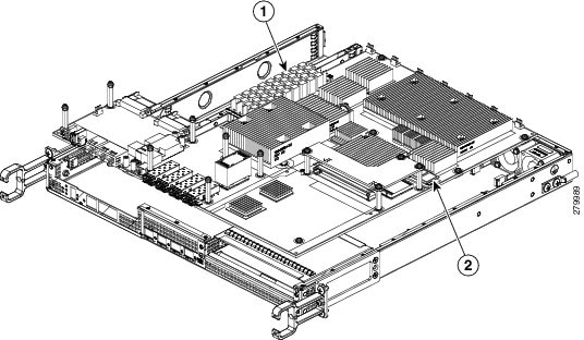

Warning

Never install an AC power module and a DC power module in the same chassis. Statement 1050


SUMMARY STEPS

  1. Insert an AC power supply in power supply slot 0 or power supply slot 1 until it is fully seated.
  2. Tighten the captive screws.
  3. Insert the AC power cable.
  4. Plug the power supply cable into the power source.
  5. Turn the power supply Standby switch to On (|) position.

DETAILED STEPS


Step 1

Insert an AC power supply in power supply slot 0 or power supply slot 1 until it is fully seated.

Step 2

Tighten the captive screws.

Step 3

Insert the AC power cable.

Step 4

Plug the power supply cable into the power source.

Step 5

Turn the power supply Standby switch to On (|) position.


What to do next

This completes the procedure for installing the AC power supply in the Cisco ASR 1004 Router.

Removing and Replacing a DC Power Supply in Cisco ASR 1004 Router

This section provides information about removing and installing a DC power supply in the Cisco ASR 1004 Router.


Warning

When you install the unit, the ground connection must always be made first and disconnected last. Statement 1046


Warning

Before performing any of the following procedures, ensure that power is removed from the DC circuit. Statement 1003


Warning

Only trained and qualified personnel should be allowed to install, replace, or service this equipment. Statement 1030


Warning

Installation of the equipment must comply with local and national electrical codes. Statement 1074


The following figure shows the DC power supply and components for the Cisco ASR 1004 Router.
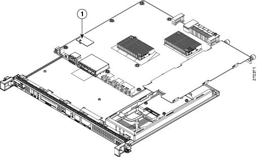
Figure 49. Cisco ASR 1004 Router DC Power Supply

1

DC power supply terminal block and plastic cover

5

DC power supply ground symbol

2

DC power supply LEDs

6

DC power supply On (|)/ Off (O)

3

DB-25 alarm connector*

7

DC power supply handle

4

DC power supply fan

*For information about the DB-25 alarm connector, how it works, and Cisco ASR 1000 route processor LEDs, see the xref “How Cisco ASR1000-RP Alarm Monitoring Works” section on page 2-20.

Note: Shielded cables must be used to connect to the DB-25 alarm connector on both the AC and DC power supplies, in order to comply with FCC/EN55022/CISPR22 Class A emissions requirements.

Removing the DC Power Supply from the Cisco ASR 1004 Router

Before you can remove a DC power supply from the Cisco ASR 1004 Router, you must remove power from the power supply. Follow these steps to remove power and the DC power supply from the chassis.

SUMMARY STEPS

  1. Make certain that the chassis ground is connected before you begin removing the DC power supply.
  2. Switch the power supply circuit breaker switch to Off (O).
  3. Locate the terminal block on the rear of the chassis on the power supply. The following figure shows the DC power supply terminal block.
  4. Remove the slotted plastic cover from the terminal block.
  5. Locate the power supply ground stud (see xref fig). Remove the ground (GND) cable from the DC power supply.
  6. Loosen and remove the Kepnut screw, washer, and ground lug in that order.
  7. Loosen the captive screws on the DC power supply.
  8. Grasping the power supply handles, pull the power supply from the chassis.
  9. Replace the DC power supply within five minutes.

DETAILED STEPS


Step 1

Make certain that the chassis ground is connected before you begin removing the DC power supply.

Step 2

Switch the power supply circuit breaker switch to Off (O).

Step 3

Locate the terminal block on the rear of the chassis on the power supply. The following figure shows the DC power supply terminal block.

Step 4

Remove the slotted plastic cover from the terminal block.

1

Negative terminal

3

Ground stud

2

Positive terminal

4

Terminal block plastic cover screws

  1. Loosen and remove the two #10 screws from the plastic cover. The plastic cover has slots that help to slide it out towards the right.

  2. Using a nut driver (7/16 size), unscrew the positive kepnut, positive cable, and the flat washer, in that order. The terminal block houses two double-hole barrel lugs.

  3. Follow Step 4b and remove the negative cable.

    The following figure shows the DC power supply terminal block with lead wires connected.

    Figure 50. Cisco ASR 1004 Router DC Power Supply Terminal Block Lead Wire Connection

    1

    Ground stud and wire

    4

    Flat washer

    2

    Ground lug nut

    5

    Kepnut screw

    3

    Ground symbol

Step 5

Locate the power supply ground stud (see xref fig). Remove the ground (GND) cable from the DC power supply.

Step 6

Loosen and remove the Kepnut screw, washer, and ground lug in that order.

Warning 

When installing the unit, the ground connection must always be made first and disconnected last.

Step 7

Loosen the captive screws on the DC power supply.

Note 
Four power supplies must be installed in the chassis at all times, with a minimum of two power supplies (one per zone) connected to the mains in order to power on the system and ensure sufficient cooling. The system fans are inside the power supply units and must spin for cooling. Because all the system fans can be powered by one power supply, the second power supply unit does not have to be powered on, but must be connected.
Caution 

If you remove a power supply from a system that has four power supplies that are connected and powered on, the system can run only for a maximum of five minutes before shutting down. However, because the fans and power elements are independent within the power supply, the replacement power supply does not have to be energized within five minutes. The only requirement is that the power supply be installed in the chassis in order to energize the fans and maintain proper system cooling.

Step 8

Grasping the power supply handles, pull the power supply from the chassis.

Step 9

Replace the DC power supply within five minutes.


What to do next

This completes the procedure of removing a DC power supply from the Cisco ASR 1004 Router.
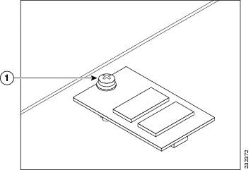
Replacing the DC Power Supply in Cisco ASR 1004 Router


Note

The color coding of the DC input power supply leads depends on the color coding of the DC power source at your site. Typically, green or green/yellow is used for ground (GND), black is used for negative (–) terminal and red is used for the positive (+) terminal. Make certain the lead color coding you choose for the DC input power supply matches lead color coding used at the DC power source.

Warning

When you install the unit, the ground connection must always be made first and disconnected last. Statement 1046


To install the DC power supply, follow these steps:

SUMMARY STEPS

  1. Make certain that the chassis ground is connected before you begin installing the DC power supply.
  2. Grasp the DC power supply by the two handles and carefully slide it into the chassis. Make sure you align the rear connector to the backplane until it is fully seated.
  3. Tighten the captive screws on the power supply.
  4. Locate the power supply terminal block and remove the plastic cover from the terminal block:
  5. You must wrap the positive and negative cables with sleeving. Take each ground wire and cover the area from the lug to the wire with heavy shrink sleeving (see xref fig).
  6. Attach the GND wire first and follow this order:
  7. Tighten the KEP-style hex nut screws (use the screwdriver to tighten the ground screw in the terminal block to a torque of 18-22 in-lbs) on the power supply studs
  8. Insert the positive ground cable. Replace the ground lug with cable in the following order:
  9. Tighten the KEP-style hex nut screws (use the screwdriver to tighten the positive ground screw in the terminal block to a torque of 18-22 in-lbs) on the power supply ground studs and repeat the same steps for the negative ground stud and wire (see xref fig).
  10. Use tie wraps to secure the wires, so that the wires are not pulled from the terminal block by casual contact. Tie-wrap studs are located below the power supply terminal block.
  11. Replace the terminal block plastic cover and tighten the screws. The plastic cover slides in easily over the terminal block.
  12. If you taped the circuit breaker, then remove the tape from the circuit-breaker switch handle and move the circuit-breaker handle to the on position.
  13. Switch the power supply circuit breaker switch to the On (|) position.

DETAILED STEPS


Step 1

Make certain that the chassis ground is connected before you begin installing the DC power supply.

Step 2

Grasp the DC power supply by the two handles and carefully slide it into the chassis. Make sure you align the rear connector to the backplane until it is fully seated.

Step 3

Tighten the captive screws on the power supply.

Step 4

Locate the power supply terminal block and remove the plastic cover from the terminal block:

  1. Unscrew and remove the two #10 screws.

  2. Slide the cover off the terminal block towards the right.

    Caution 

    Before you continue to install the terminal block ground wires, stop and perform Step 5 to prevent any contact with metal lead on the ground wire and the plastic cover.

Step 5

You must wrap the positive and negative cables with sleeving. Take each ground wire and cover the area from the lug to the wire with heavy shrink sleeving (see xref fig).

Step 6

Attach the GND wire first and follow this order:

  1. Flat Washer

  2. Ground lug with grounding wire

  3. KEPnut screw

Step 7

Tighten the KEP-style hex nut screws (use the screwdriver to tighten the ground screw in the terminal block to a torque of 18-22 in-lbs) on the power supply studs

Step 8

Insert the positive ground cable. Replace the ground lug with cable in the following order:

  1. Flat Washer

  2. Ground lug with positive wire

  3. Kepnut screw

Step 9

Tighten the KEP-style hex nut screws (use the screwdriver to tighten the positive ground screw in the terminal block to a torque of 18-22 in-lbs) on the power supply ground studs and repeat the same steps for the negative ground stud and wire (see xref fig).

Note 
Secure the wires coming in from the terminal block so that they cannot be disturbed by casual contact.
Step 10

Use tie wraps to secure the wires, so that the wires are not pulled from the terminal block by casual contact. Tie-wrap studs are located below the power supply terminal block.

Note 
The ground wire must contain a loop when securing it to the tie-wrap tab to prevent it from being pulled out.
Step 11

Replace the terminal block plastic cover and tighten the screws. The plastic cover slides in easily over the terminal block.

Step 12

If you taped the circuit breaker, then remove the tape from the circuit-breaker switch handle and move the circuit-breaker handle to the on position.

Step 13

Switch the power supply circuit breaker switch to the On (|) position.


What to do next

This completes the procedure for connecting the DC power supply in the Cisco ASR 1004 Router.
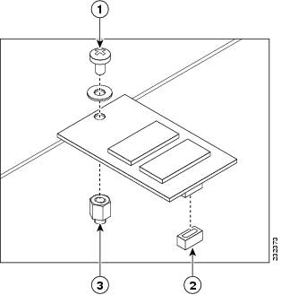
Removing and Replacing the Cisco ASR 1002 Router Power Supplies

The Cisco ASR 1002 Router contains the following power supplies:

  • AC power supply

  • –48 VDC power supply

  • +24 VDC power supply

This section contains the procedures to remove and replace these power supplies in the Cisco ASR 1002 Router, Cisco ASR 1002-F Router, and Cisco ASR 1002-X Router.
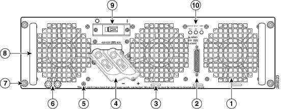

Note

Unless otherwise noted, the Cisco ASR 1002-F Router AC and –48 VDC power supply and removal and installation remain the same as the Cisco ASR 1002 Router.
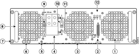

This section contains the following topics:

Removing and Replacing an AC Power Supply in Cisco ASR 1002 Router

This section provides information about removing and replacing an AC power supply in the Cisco ASR 1002 Router.


Note

You must have both power supplies installed in the Cisco router.

The Cisco ASR 1002 Router has two of the same type power supplies in power supply slot 0 and power supply slot 1. The following figure shows the Cisco ASR 1002 Router AC power supply.

Figure 51. Cisco ASR 1002 Router AC Power Supply

1

AC power supply ESD socket

5

Fan

2

AC power supply slot 0 label

6

Captive installation screw

3

AC power supply On (|) /Off (O) switch

7

AC power supply slot 1 label

4

AC power supply LEDs

8

AC power inlet

Removing the AC Power Supply from Cisco ASR 1002 Router

To remove the AC power supply from the Cisco ASR 1002 Router, follow these steps:

SUMMARY STEPS

  1. Slip on the ESD-preventive wrist strap that was included in the accessory kit.
  2. Turn the switch to the Off (O) position, remove wiring, and unplug the AC cord.
  3. Unscrew all of the power supply captive screws.
  4. Grasping the power supply handles, pull the power supply from the chassis.
  5. Replace the AC power supply within five minutes.

DETAILED STEPS


Step 1

Slip on the ESD-preventive wrist strap that was included in the accessory kit.

Step 2

Turn the switch to the Off (O) position, remove wiring, and unplug the AC cord.

Step 3

Unscrew all of the power supply captive screws.

Note 
Two power supplies must be installed in the chassis at all times, with a minimum of one power supply connected to the mains in order to power on the system and ensure sufficient cooling. The system fans are inside the power supply units and must spin for cooling. Because all the system fans can be powered by one power supply, the second power supply unit does not have to be powered on, but must be connected.
Caution 

If you remove a power supply from a system that are connected and powered on, the system can run only for a maximum of five minutes before shutting down. However, because the fans and power elements are independent within the power supply, the replacement power supply does not have to be energized within five minutes. The only requirement is that the power supply be installed in the chassis in order to energize the fans and maintain proper system cooling.

Step 4

Grasping the power supply handles, pull the power supply from the chassis.

Step 5

Replace the AC power supply within five minutes.


What to do next

This completes the procedure for removing the AC power supply from the Cisco ASR 1002 chassis.

Replacing the AC Power Supply in Cisco ASR 1002 Router

This section provides information about installing an AC power supply in the Cisco ASR 1002 Router.


Warning

Never install an AC power module and a DC power module in the same chassis. Statement 1050


SUMMARY STEPS

  1. Insert an AC power supply in power supply slot 0 or power supply slot 1 until it is fully seated.
  2. Tighten the captive screws.

DETAILED STEPS


Step 1

Insert an AC power supply in power supply slot 0 or power supply slot 1 until it is fully seated.

Step 2

Tighten the captive screws.


Replacing the AC Power Supply in Cisco ASR 1002 Router

To connect AC power to the Cisco ASR 1002 Router, follow these steps:

SUMMARY STEPS

  1. At the rear of the router, check that the power switch is in the Off (O) position.
  2. Insert the AC power cable into the AC power inlet and then turn On (|).
  3. To ensure that the AC power cord does not interfere with other cables or wires, dress the AC power cable in one of the following ways.
  4. Plug the AC power supply cable into the AC power source.

DETAILED STEPS


Step 1

At the rear of the router, check that the power switch is in the Off (O) position.

Note 
Turn the power switch to the On (|) position after both power sides of the power cord are connected.
Step 2

Insert the AC power cable into the AC power inlet and then turn On (|).

Step 3

To ensure that the AC power cord does not interfere with other cables or wires, dress the AC power cable in one of the following ways.

  1. Leave a small service loop in the AC power cord from the inlet and then secure the power cord through the AC power supply handle as shown in the following figure. Alternatively, go to step 3b.

    Figure 52. Cisco ASR 1002 Router AC Power Supply and Cord in Slot 1

    1

    AC power cord

  2. Take the power cord and run it below the handles of the power supply in slot 1and the power supply in slot 0 (left). Make sure the power cord is hanging loosely so that it cannot be disconnected from the AC power inlet (see the following figure).

    Figure 53. Cisco ASR 1002 Router AC Power Cord Through AC Power Supply 0 and 1
    Caution 

    Do not run the AC power cord through the either power supply handles as shown in the following figure.

    Figure 54. Cisco ASR 1002 Router Improper AC Power Cord Cabling
    Note 
    Using a tie wrap for the AC power cable is optional and not necessary. However, if you do attach the AC power cable to a power supply tab and then you remove the AC power cable for some reason, check for any damage to the cable after you cut the tie wrap off. If the power cord is damaged, replace it immediately.
Step 4

Plug the AC power supply cable into the AC power source.

Note 
Two power supplies must be installed in the chassis at all times, with a minimum of one power supply connected to the mains in order to power on the system and ensure sufficient cooling. The system fans are inside the power supply units and must spin for cooling. Because all the system fans can be powered by one power supply, the second power supply unit does not have to be powered on, but must be connected.
Caution 

If you remove a power supply from a system that are connected and powered on, the system can run only for a maximum of five minutes before shutting down. However, because the fans and power elements are independent within the power supply, the replacement power supply does not have to be energized within five minutes. The only requirement is that the power supply be installed in the chassis in order to energize the fans and maintain proper system cooling.


What to do next

This completes the procedure for installing the AC power supply in the Cisco ASR 1002 Router.

Removing and Replacing a –48 VDC Power Supply in Cisco ASR 1002 Router

This section provides information about removing and installing a –48 VDC power supply in the Cisco ASR 1002 Router.


Warning

When you install the unit, the ground connection must always be made first and disconnected last. Statement 1046
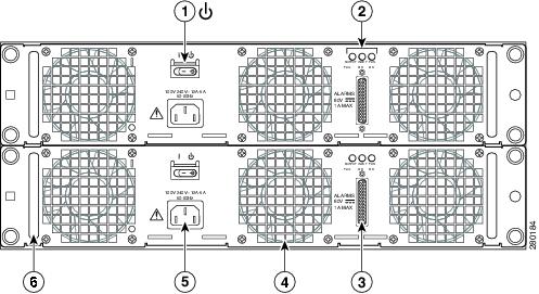


Warning

Before performing any of the following procedures, ensure that power is removed from the DC circuit. Statement 1003


Warning

Only trained and qualified personnel should be allowed to install, replace, or service this equipment. Statement 1030


Warning

Installation of the equipment must comply with local and national electrical codes. Statement 1074


The following figure shows the –48 VDC power supply and components for the Cisco ASR 1002 Router.

Figure 55. Cisco ASR 1002 Router –48 VDC Power Supply

1

Power supply ESD socket

6

Power supply captive installation screw

2

Power supply slot 0 label

7

Power supply slot 1 label

3

Power supply switch Standby/On (|)

8

Ground (GND)

4

Power supply LEDs

9

Positive lead

5

Fan

10

Negative lead

Removing the –48 VDC Power Supply from Cisco ASR 1002 Router

Before you can remove a –48 VDC power supply from the Cisco ASR 1002 Router, you must remove input power going to the power supply.


Caution

Make certain that the chassis ground is connected before you begin removing and installing the power supply.


To remove the –48 VDC power supply from the Cisco ASR 1002 Router, follow this procedure:

SUMMARY STEPS

  1. Slip on the ESD-preventive wrist strap that was included in the accessory kit.
  2. Place the power supply Standby switch in the Standby (see the following figure) position.
  3. Turn off the branch circuit breaker before touching terminal screws. Then start loosening the terminal block screws to remove wires.
  4. Remove the leads from the terminal block in the following order.
  5. Unscrew all of the power supply captive screws.
  6. Grasping the power supply handles, pull the power supply from the chassis.
  7. Replace the –48 VDC power supply within five minutes.

DETAILED STEPS


Step 1

Slip on the ESD-preventive wrist strap that was included in the accessory kit.

Step 2

Place the power supply Standby switch in the Standby (see the following figure) position.

Figure 56. Cisco ASR 1002 Router –48 VDC Power Supply Terminal Block

1

Negative terminal

3

Ground terminal

2

Positive terminal

Step 3

Turn off the branch circuit breaker before touching terminal screws. Then start loosening the terminal block screws to remove wires.

Step 4

Remove the leads from the terminal block in the following order.

  1. Negative lead

  2. Positive lead

  3. Ground lead

Step 5

Unscrew all of the power supply captive screws.

Note 
Two power supplies must be installed in the chassis at all times, with a minimum of one power supply connected to the mains in order to power on the system and ensure sufficient cooling. The system fans are inside the power supply units and must spin for cooling. Because all the system fans can be powered by one power supply, the second power supply unit does not have to be powered on, but must be connected.
Caution 

If you remove a power supply from a system that are connected and powered on, the system can run only for a maximum of five minutes before shutting down. However, because the fans and power elements are independent within the power supply, the replacement power supply does not have to be energized within five minutes. The only requirement is that the power supply be installed in the chassis in order to energize the fans and maintain proper system cooling.

Step 6

Grasping the power supply handles, pull the power supply from the chassis.

Step 7

Replace the –48 VDC power supply within five minutes.


What to do next

This completes the procedure of removing a –48 VDC power supply from the Cisco ASR 1002 Router.

Replacing the –48 VDC Power Supply in Cisco ASR 1002 Router

The –48 VDC power supply input connector is a Euro-style terminal block. Features are provide for strain relieving the input wires from the terminal block on the front panel. The ground wire must contain a loop when secured to prevent any strain on the wires. The connection order is negative (–), positive (+), and GND. The recommended branch circuit breaker for the Cisco ASR 1002 Router –48 VDC power supply is 30 A. Use an AWG #10 gauge wire on the 30 A circuit.

This section describes how to connect the –48 VDC power supply in the Cisco ASR 1002 Router.


Note

The color coding of the –48 VDC input power supply leads depends on the color coding of the –48 VDC power source at your site. Typically, green or green/yellow is used for ground. Make certain the lead color coding you choose for the –48 VDC input power supply matches lead color coding used at the –48 VDC power source.

Warning

When you install the unit, the ground connection must always be made first and disconnected last. Statement 1046


SUMMARY STEPS

  1. At the rear of the router, check that the power Standby switch is in the Standby position.
  2. Ensure that the positive and negative leads are disconnected from the site power source and the source circuit breaker is turned off.
  3. Using a wire stripper, strip approximately 0.55 inch (14 mm) from the negative, positive, and ground leads.
  4. Insert the stripped end of the ground lead all the way into the ground lead receptacle on the –48 VDC input power supply, and tighten the receptacle screw using a 3.5 mm flat-blade screwdriver (see the following figure).
  5. Insert the stripped end of the positive lead all the way into the positive lead receptacle and tighten the receptacle screw using the same 3.5mm flat-blade screwdriver. Repeat this step for the negative lead.
  6. After tightening the receptacle screw for the ground, and leaving the extra service loop in the ground lead, use a cable tie to secure the three leads to the power supply faceplate tie-wrap tab.
  7. Turn on the branch source breaker.
  8. Place the power supply standby switch to the On (|) position. The power supply LEDs light when power is supplied to the router.

DETAILED STEPS


Step 1

At the rear of the router, check that the power Standby switch is in the Standby position.

Step 2

Ensure that the positive and negative leads are disconnected from the site power source and the source circuit breaker is turned off.

Step 3

Using a wire stripper, strip approximately 0.55 inch (14 mm) from the negative, positive, and ground leads.

Step 4

Insert the stripped end of the ground lead all the way into the ground lead receptacle on the –48 VDC input power supply, and tighten the receptacle screw using a 3.5 mm flat-blade screwdriver (see the following figure).

Figure 57. Cisco ASR 1002 Router –48 VDC Power Supply Terminal Block Lead Wire Connection

1

Ground lead wire with service loop

3

Power negative lead wire

2

Power positive lead wire

4

Power supply Standby switch

Step 5

Insert the stripped end of the positive lead all the way into the positive lead receptacle and tighten the receptacle screw using the same 3.5mm flat-blade screwdriver. Repeat this step for the negative lead.

Note 
Make sure the entire stripped end of each lead is inserted all the way into its receptacle. If any exposed wire at the stripped end of a lead is visible after inserting the lead into its receptacle, remove the lead from the receptacle, use the wire stripper to cut the stripped end of the lead, and repeat Step 3 through Step 5.
Step 6

After tightening the receptacle screw for the ground, and leaving the extra service loop in the ground lead, use a cable tie to secure the three leads to the power supply faceplate tie-wrap tab.

Caution 

When securing the ground, positive, and negative –48 VDC-input leads to the power supply faceplate, leave extra service loop in the ground lead to ensure that the ground lead is the last lead to disconnect from the power supply if a great deal of strain is placed on all three leads as shown in xref fig.

Step 7

Turn on the branch source breaker.

Step 8

Place the power supply standby switch to the On (|) position. The power supply LEDs light when power is supplied to the router.


Removing and Replacing a +24 VDC Power Supply in Cisco ASR 1002 Router

This section provides information about removing and replacing a +24 VDC power supply in the Cisco ASR 1002 Router.

Before you begin, read the following notices:

  • The labeling displays +27 VDC INPUT. This labeling describes the nominal voltage provided at a cell site.

  • Observe the polarity location—Unlike the polarity labels of the –48 VDC power supply (ground, positive, negative), the polarity labels on the +24 VDC are ground, negative, positive as shown in xref fig from right to left as they appear on the actual power supply unit.

  • The ground (GND) lead is always installed first and removed last.

  • The +24 VDC power supply uses a spring loaded terminal block; therefore have the recommended screwdriver size available.

  • Review the diagrams to see how the wire is stripped and how the screwdriver is inserted at an angle into the terminal block.

  • Have the following equipment available to install and remove the +24 VDC power supply:

    • Phoenix Contact 3.5mm flat-blade screwdriver or equivalent

    • Wire-stripping tool for stripping 8-gauge wire


Warning

When you install the unit, the ground connection must always be made first and disconnected last. Statement 1046


Warning

Before performing any of the following procedures, ensure that power is removed from the DC circuit. Statement 1003


Warning

Only trained and qualified personnel should be allowed to install, replace, or service this equipment. Statement 1030


Warning

Installation of the equipment must comply with local and national electrical codes. Statement 1074


The following figure shows the +24 VDC power supply and components for the Cisco ASR 1002 Router.

Figure 58. Cisco ASR 1002 Router +24 VDC Power Supply

1

+24 VDC terminal block

6

Standby/On switch

2

Positive (+) lead

7

Captive fastener

3

Negative (-) lead

8

Power supply tabs

4

Ground (GND) lead

9

+27 VDC INPUT label

5

Power supply LEDs

Removing the +24 VDC Power Supply from Cisco ASR 1002 Router

Before you can remove a +24 VDC power supply from the Cisco ASR 1002 Router, you must remove input power going to the power supply.


Caution

Make certain that the chassis ground lead wire is connected before you begin removing and installing the power supply.


To remove the +24 VDC power supply from the Cisco ASR 1002 Router, follow these steps:

SUMMARY STEPS

  1. Slip on the ESD-preventive wrist strap that was included in the accessory kit.
  2. Place the power supply Standby switch in the Standby (see xref fig, item 6) position.
  3. Using the recommended screwdriver, insert the screwdriver at an angle, pushing forward to release the internal spring contact on the lead wire and then gently pull out the wire.
  4. Remove screwdriver and continue removing the remaining lead wires from the terminal block, repeating Step 4 through Step 5 for each lead wire.
  5. Unscrew the two power supply captive screws.
  6. Grasping the power supply handles, pull the power supply from the chassis.
  7. Replace the +24 VDC power supply within five minutes.

DETAILED STEPS


Step 1

Slip on the ESD-preventive wrist strap that was included in the accessory kit.

Step 2

Place the power supply Standby switch in the Standby (see xref fig, item 6) position.

Step 3

Using the recommended screwdriver, insert the screwdriver at an angle, pushing forward to release the internal spring contact on the lead wire and then gently pull out the wire.

The screwdriver remains pushed into the spring release opening until the wire is completely removed.

Step 4

Remove screwdriver and continue removing the remaining lead wires from the terminal block, repeating Step 4 through Step 5 for each lead wire.

Tip 

If the 8-gauge input wiring is very rigid or a solid wire, then a screwdriver might not be necessary. As a result of using few-strand heavy gauge wiring, you can insert the wire into the terminal block to release the spring tension. After inserting the lead wire, gently pull on the wire to make certain that the wire is secured. Make certain that no wire is exposed and that only wire insulation is seen.

Step 5

Unscrew the two power supply captive screws.

Note 
Two power supplies must be installed in the chassis at all times, with a minimum of one power supply connected to the mains in order to power on the system and ensure sufficient cooling. The system fans are inside the power supply units and must spin for cooling. Because all the system fans can be powered by one power supply, the second power supply unit does not have to be powered on, but must be connected.
Caution 

If you remove a power supply from a system that are connected and powered on, the system can run only for a maximum of five minutes before shutting down. However, because the fans and power elements are independent within the power supply, the replacement power supply does not have to be energized within five minutes. The only requirement is that the power supply be installed in the chassis in order to energize the fans and maintain proper system cooling.

Step 6

Grasping the power supply handles, pull the power supply from the chassis.

Step 7

Replace the +24 VDC power supply within five minutes.


What to do next

This completes the procedure of removing a +24 VDC power supply from the Cisco ASR 1002 Router.

Replacing the +24 VDC Power Supply in Cisco ASR 1002 Router

The +24 VDC power supply uses a spring-loaded terminal block. The input terminal block requires 8 AWG multi-strand wiring to support input current. Features are provide for strain relieving the input wires from the terminal block on the front panel. The recommended branch circuit breaker for the Cisco ASR 1002 Router +24 VDC power supply is 40 A UL listed circuit breaker.

Before you begin, read these important notices about the +24 VDC power supply:

  • The labeling displays +27 VDC INPUT. This labeling describes the nominal voltage provided at a cell site.
  • Observe the polarity—Unlike the polarity labels of the –48 VDC power supply (ground, positive, negative), the polarity labels on the +24 VDC are ground, negative, positive as shown in xref fig from right to left as they appear on the actual power supply unit.
  • The ground (GND) lead is always installed first and removed last.
  • The +24 VDC power supply uses a spring loaded terminal block; therefore have the recommended screwdriver size available.
  • Review the diagrams to see how the wire is stripped and how the screwdriver is inserted at an angle into the terminal block.
  • Have the following equipment available to install and remove the +24 VDC power supply:
    • 3.5mm flat-blade screwdriver
    • 8-gauge wire

The following figure shows the +24 VDC power supply for the Cisco ASR 1002 Router.

Figure 59. +24 VDC Power Supply for the Cisco ASR 1002 Router

1

+24 VDC terminal block

6

Standby/On switch

2

Positive (+) lead

7

Captive fastener

3

Negative (-) lead

8

Power supply tabs

4

Ground (GND) lead

9

+27 VDC INPUT label

5

Power supply LEDs

This section describes how to connect the +24 VDC power supply in the Cisco ASR 1002 Router.


Note

The color coding of the +24 VDC input power supply leads depends on the color coding of the +24 VDC power source at your site. Typically, green or green/yellow is used for ground. Make certain the lead color coding you choose for the +24 VDC input power supply matches lead color coding used at the +24 VDC power source. Most commonly used wire color-coding is red for positive (+) lead and black for negative (–) lead.

Warning

When you install the unit, the ground connection must always be made first and disconnected last. Statement 1046


To connect +24 VDC power supply in the Cisco ASR 1002 Router, follow these steps:

SUMMARY STEPS

  1. At the rear of the router, check that the power Standby switch is in the Standby position.
  2. Ensure that the positive and negative leads are disconnected from the site power source and the source circuit breaker is turned off.
  3. Using a wire stripper, strip the recommended amount of wire insulation which is 15mm (0.6 inch) from the negative, positive, and ground leads.
  4. The following figure shows the wire strip and insulation location.
  5. Using a 3.5mm screwdriver, insert the screwdriver at an angle to release the spring while you install the stripped lead wire (see the following figure).
  6. Carefully push the screwdriver at an angle forward until you relieve the spring contact.
  7. With the screwdriver still inserted, gently push the lead wire (ground lead first) in until there is no copper wire showing as shown in the following figure.
  8. Make certain no copper wire is visible as shown in the following figure which shows the lead wire fully inserted.
  9. After the lead wire is fully inserted, hold the lead wire in place by pressing inward while you remove the screwdriver to release the spring to tension down on the installed lead wire, then perform these steps:
  10. Repeat Steps 5 through Step 10 for each lead wire. The following figure shows the leads wires installed in the terminal block.
  11. After inserting the ground wire leave an extra service loop in the ground lead to ensure that the ground lead is the last lead to disconnect from the power supply if a great deal of strain is placed on all three leads as shown in the following figure, callout 1.
  12. After tightening the receptacle screw for the ground, and leaving the extra service loop in the ground lead, use a cable tie to secure the three leads to the power supply faceplate tie-wrap tab as shown in xref fig, callout 5.
  13. Turn on the branch source breaker.
  14. Place the power supply standby switch to the On (|) position. The power supply LEDs light when power is supplied to the router.

DETAILED STEPS


Step 1

At the rear of the router, check that the power Standby switch is in the Standby position.

Step 2

Ensure that the positive and negative leads are disconnected from the site power source and the source circuit breaker is turned off.

Step 3

Using a wire stripper, strip the recommended amount of wire insulation which is 15mm (0.6 inch) from the negative, positive, and ground leads.

Note 
The stripping length is common to all types of wire used.
Step 4

The following figure shows the wire strip and insulation location.

Figure 60. Wire Strip and Lead for the +24 VDC Terminal Block

1

Lead wire stripped area

Step 5

Using a 3.5mm screwdriver, insert the screwdriver at an angle to release the spring while you install the stripped lead wire (see the following figure).

Figure 61. Inserting a Screwdriver into the +24 VDC Power Supply Terminal Block
Step 6

Carefully push the screwdriver at an angle forward until you relieve the spring contact.

Step 7

With the screwdriver still inserted, gently push the lead wire (ground lead first) in until there is no copper wire showing as shown in the following figure.

Caution 

Check that there is no copper portion of the lead wire exposed. Only wire insulation must be visible.

Caution 

Do not install wire into the terminal block that has not had its insulation removed.

The following figure shows the +24 VDC power supply lead wire inserted into the terminal block.

Figure 62. Cisco ASR 1002 Router +24 VDC Power Supply Lead Wire Inserted into the Terminal Block

1

Lead wire insulation

2

Copper wire

Step 8

Make certain no copper wire is visible as shown in the following figure which shows the lead wire fully inserted.

Figure 63. Cisco ASR 1002 Router +24 VDC Power Supply Lead Wire Fully Inserted

1

Fully-inserted lead wire

Step 9

After the lead wire is fully inserted, hold the lead wire in place by pressing inward while you remove the screwdriver to release the spring to tension down on the installed lead wire, then perform these steps:

  1. Hold the lead wire in place while you are removing the screwdriver.

  2. Once the screwdriver is completely removed, gently pull on the lead wire to make certain that the lead wire is securely installed.

    The following figure shows a lead wire fully inserted and the screwdriver removed while you gently pull on the lead to make certain it is secured in the terminal block.

    Figure 64. Removing a Screwdriver from the +24 VDC Power Supply Terminal Block

    1

    Gently pull on lead wire.

Step 10

Repeat Steps 5 through Step 10 for each lead wire. The following figure shows the leads wires installed in the terminal block.

Figure 65. Cisco +24 VDC Power Supply Terminal Block with Lead Wires Installed

1

Positive lead wire

3

Ground lead wire

2

Negative lead wire

Note 
Make sure the stripped end of each lead wire is twisted tightly together. This makes insertion easier. Then make certain the entire lead wire is inserted all the way into its receptacle. If any exposed wire at the stripped end of a lead is visible after inserting the lead into its receptacle, remove the lead from the receptacle, use the wire stripper to cut the stripped end of the lead, and then reinsert.
Caution 

When securing the ground, positive, and negative +24 VDC-input leads to the power supply faceplate, leave extra service loop in the ground (GND) lead to ensure that the ground lead is the last lead wire to disconnect from the power supply if a great deal of strain is placed on all three leads.

Step 11

After inserting the ground wire leave an extra service loop in the ground lead to ensure that the ground lead is the last lead to disconnect from the power supply if a great deal of strain is placed on all three leads as shown in the following figure, callout 1.

Figure 66. Cisco ASR 1002 Router +24 VDC Power Supply Terminal Block Service Loop

1

Ground lead wire with service loop

4

+24 VDC power supply Standby switch

2

Negative lead wire

5

Power supply tabs

3

Positive lead wire

Step 12

After tightening the receptacle screw for the ground, and leaving the extra service loop in the ground lead, use a cable tie to secure the three leads to the power supply faceplate tie-wrap tab as shown in xref fig, callout 5.

Step 13

Turn on the branch source breaker.

Step 14

Place the power supply standby switch to the On (|) position. The power supply LEDs light when power is supplied to the router.


What to do next

This completes the steps for installing the +24 VDC power supply in the Cisco ASR 1002 Router.

Removing and Replacing the Cisco ASR 1013 Router Power Supplies

The Cisco ASR 1013 Router contains power supplies that are field replaceable units. This section contains the following topics:

Removing and Replacing an AC Power Supply in Cisco ASR 1013 Router

This section provides information about removing and replacing an AC power supply in the Cisco ASR 1013 Router.

Removing the AC Power Supply from Cisco ASR 1013 Router

Because of the power supply redundancy, there is no need to power off the Cisco ASR 1013 Router before removing one of the AC power supplies.

The Cisco ASR 1013 Router has two of the same type power supplies in power supply slot 0 and power supply slot 1.

To remove the Cisco ASR 1013 Router AC power supply that is not operating normally (and then replace the AC power supply within five minutes), follow this procedure:

SUMMARY STEPS

  1. Slip on the ESD-preventive wrist strap that was included in the accessory kit.
  2. Before you turn off a power supply, make certain the chassis is grounded.
  3. Turn the power supply standby switch to the Standby position. See the following figure.
  4. Unplug the power cable from the AC inlet on the back of the power supply and the power source.
  5. Unscrew the power supply captive screws.
  6. Grasping the power supply handles, pull the power supply from the chassis.
  7. Replace the AC power supply within five minutes.

DETAILED STEPS


Step 1

Slip on the ESD-preventive wrist strap that was included in the accessory kit.

Step 2

Before you turn off a power supply, make certain the chassis is grounded.

Step 3

Turn the power supply standby switch to the Standby position. See the following figure.

Figure 67. Cisco ASR 1013 Router AC Power Inlet and Standby Switch

1

AC power supply fan

6

AC power inlet

2

DB-25 alarm connector*

7

AC power supply standby switch. A standby switch is not considered a disconnect.

3

Cable tie wrap tabs

8

Protective sides around the standby switch

4

AC power supply captive screws

9

AC power supply LEDs

5

AC power supply handle

*For information about the DB-25 alarm connector, how it works, and Cisco ASR 1000 series route processor LEDs, see the xref section.

Note: Shielded cables must be used to connect to the DB-25 alarm connector on both the AC and DC power supplies, in order to comply with FCC/EN55022/CISPR22 Class A emissions requirements.

Step 4

Unplug the power cable from the AC inlet on the back of the power supply and the power source.

Step 5

Unscrew the power supply captive screws.

Note 
The Cisco ASR 1013 router has two power zones, each containing two power supplies for a redundant system. Power supplies must be installed in the chassis at all times to ensure sufficient cooling. The system fans are inside the power supply units and must spin for cooling. Because all the system fans can be powered by one power supply, the second power supply unit does not have to be powered on, but it must be installed.
Caution 

If you remove a power supply, the system can run for a maximum of five minutes before the system shuts down. The fans and power elements are independent within the power supply. Therefore, it is not required that the replacement power supply be energized within five minutes. The only requirement is that the power supply be installed in the chassis, which energizes the fans and maintains proper system cooling.

Step 6

Grasping the power supply handles, pull the power supply from the chassis.

Step 7

Replace the AC power supply within five minutes.


What to do next

This completes the procedure for removing the AC power supply from the Cisco ASR 1013 chassis.

Replacing the AC Power Supply in Cisco ASR 1013 Router

This section provides information about installing an AC power supply in the Cisco ASR 1013 Router.


DANGER

Never install an AC power module and a DC power module in the same chassis. Statement 1050


SUMMARY STEPS

  1. Insert an AC power supply in power supply slot 0 or power supply slot 1 until it is fully seated.
  2. Tighten the captive screws.
  3. Insert the AC power cable.
  4. Plug the power supply cable into the power source.
  5. Turn the power supply Standby switch to the On (|) position.

DETAILED STEPS


Step 1

Insert an AC power supply in power supply slot 0 or power supply slot 1 until it is fully seated.

Step 2

Tighten the captive screws.

Step 3

Insert the AC power cable.

Step 4

Plug the power supply cable into the power source.

Step 5

Turn the power supply Standby switch to the On (|) position.


What to do next

This completes the procedure for installing the AC power supply in the Cisco ASR 1013 Router.

Removing and Replacing a DC Power Supply in Cisco ASR 1013 Router

This section provides information about removing and installing a DC power supply in the Cisco ASR 1013 Router.


Warning

When you install the unit, the ground connection must always be made first and disconnected last. Statement 1046


Warning

Before performing any of the following procedures, ensure that power is removed from the DC circuit. Statement 1003


Warning

Only trained and qualified personnel should be allowed to install, replace, or service this equipment. Statement 1030


Warning

Installation of the equipment must comply with local and national electrical codes. Statement 1074


The following figure shows the DC power supply and components for the Cisco ASR 1013 Router.

Figure 68. Cisco ASR 1013 Router DC Power Supply

1

Fan

7

DC power supply captive screw

2

DB-25 alarm connector*

8

DC power supply handle

3

Tie-wrap tab

9

Terminal block and plastic cover single screw

4

DC power supply terminal block and plastic cover

10

On/Off (|/O) circuit breaker switch

5

Ground symbol

11

Terminal block and plastic cover slot tab

6

DC power supply ground studs

12

Power supply LEDs

*For information about the DB-25 alarm connector, how it works, and Cisco ASR 1000 route processor LEDs, see the xref section.

Note: Shielded cables must be used to connect to the DB-25 alarm connector on both the AC and DC power supplies, in order to comply with FCC/EN55022/CISPR22 Class A emissions requirements.

Removing the DC Power Supply from Cisco ASR 1013 Router

Before you can remove a DC power supply from the Cisco ASR 1013 Router, you must remove power from the power supply. Follow these steps to remove power and the DC power supply from the chassis.


Caution

Make certain that the chassis ground is connected before you begin removing and installing the power supply.


SUMMARY STEPS

  1. Before servicing the power supply, switch the circuit breaker Off in your equipment area. As an additional precaution, tape the circuit breaker switch in the Off position.
  2. Slip on the ESD-preventive wrist strap that was included in the accessory kit.
  3. Switch the power supply circuit breaker switch to Off (O).
  4. Locate the terminal block on the rear of the chassis on the power supply.
  5. Remove the slotted plastic cover from the terminal block (see xref fig).
  6. Loosen the four captive screws on the DC power supply.
  7. Grasping the power supply handles, pull the power supply from the chassis.
  8. Replace the DC power supply within five minutes.

DETAILED STEPS


Step 1

Before servicing the power supply, switch the circuit breaker Off in your equipment area. As an additional precaution, tape the circuit breaker switch in the Off position.

Step 2

Slip on the ESD-preventive wrist strap that was included in the accessory kit.

Step 3

Switch the power supply circuit breaker switch to Off (O).

Step 4

Locate the terminal block on the rear of the chassis on the power supply.

The following figure shows the DC power supply terminal block and plastic cover.

Figure 69. Cisco ASR 1013 Router DC Power Supply Terminal Block and Plastic Cover

1

Negative terminal

4

Plastic cover slotted area

2

Positive terminal

5

Terminal block plastic cover single screw

3

Terminal block plastic cover

Step 5

Remove the slotted plastic cover from the terminal block (see xref fig).

  1. Loosen and remove the single screw on the plastic cover. The plastic cover has slots that help to slide it out diagonally from the terminal block.

  2. Using a nut driver (7/16 size), unsrew the positive kepnut, positive cable, and the flat washer, in that order. The terminal block houses two double-hole barrel lugs.

  3. Follow Step 4b and remove the negative cable. The following figure shows the DC power supply terminal block.

    Figure 70. Cisco ASR 1013 Router DC Power Supply Terminal Block Cable Connections

    1

    Negative lead

    3

    Protective sleeving around the stud and cable

    2

    Positive lead

    4

    Ground stud and cable

    Warning 

    When removing the unit, the ground connection must always be made first and disconnected last.

Step 6

Loosen the four captive screws on the DC power supply.

Note 
Four power supplies must be installed in the chassis at all times, with a minimum of two power supplies (one per zone) connected to the mains in order to power on the system and ensure sufficient cooling. The system fans are inside the power supply units and must spin for cooling. Because all the system fans can be powered by one power supply, the second power supply unit does not have to be powered on, but must be connected.
Caution 

If you remove a power supply from a system that has four power supplies that are connected and powered on, the system can run only for a maximum of five minutes before shutting down. However, because the fans and power elements are independent within the power supply, the replacement power supply does not have to be energized within five minutes. The only requirement is that the power supply be installed in the chassis in order to energize the fans and maintain proper system cooling.

Step 7

Grasping the power supply handles, pull the power supply from the chassis.

Step 8

Replace the DC power supply within five minutes.


What to do next

This completes the procedure of removing a DC power supply from the Cisco ASR 1013 Router.

Replacing the DC Power Supply in Cisco ASR 1013 Router


Note

The color coding of the DC input power supply leads depends on the color coding of the DC power source at your site. Typically, green or green/yellow is used for ground (GND), black is used for –48 V on negative (–) terminal and red is used for RTN on the positive (+) terminal. Make certain the lead color coding you choose for the DC input power supply matches lead color coding used at the DC power source.

Warning

When you install the unit, the ground connection must always be made first and disconnected last. Statement 1046


To install the DC power supply, follow these steps:

SUMMARY STEPS

  1. Grasp the DC power supply by the two handles and carefully slide it into the chassis. Make sure you align the rear connector to the backplane until it is fully seated.
  2. Tighten the captive screws on the power supply.
  3. Make certain that the chassis ground is connected before you begin installing the DC power supply.
  4. Locate the ground stud on the DC power supply for the GND connection which must be installed first and follow these steps:
  5. Attach the other end of the ground cable to the site ground associated to the DC power supply system that you are working on.
  6. Remove the plastic cover from the terminal block if it is still on.
  7. You must wrap the positive and negative power cables with sleeving. Take each wire and cover the area from the lug to the wire with heavy shrink sleeving as pointed out in callout 3 (see xref fig).
  8. For easier cable-management, insert the positive cable first. Replace the ground lug with cable in the following order as shown in:
  9. Tighten the Kepnut screw (use the screwdriver to tighten the ground screw in the terminal block to a torque of 20+/–2 in-lbs / 2 per.) and repeat the same steps for the negative wires.
  10. Use tie wraps to secure the wires, so that the wires are not pulled from the terminal block by casual contact. Ti-wrap studs are located below the power supply terminal block.
  11. Replace the terminal block plastic cover, which is slotted and keyed to fit correctly over the terminal block; then tighten the black screw (use the screwdriver to tighten the screw to a torque of 5 in-lbs / 1 per.).
  12. Remove the tape from the circuit-breaker On/Off switch (if there was any).
  13. Switch the circuit breaker On/Off switch to the On (|) position.

DETAILED STEPS


Step 1

Grasp the DC power supply by the two handles and carefully slide it into the chassis. Make sure you align the rear connector to the backplane until it is fully seated.

Step 2

Tighten the captive screws on the power supply.

Step 3

Make certain that the chassis ground is connected before you begin installing the DC power supply.

Step 4

Locate the ground stud on the DC power supply for the GND connection which must be installed first and follow these steps:

  1. Using the grounding lug, replace the washers and Kepnut screw in the following order.

      • Flat washer
      • Grounding cable lug
      • Kepnut screw
  2. Tighten the Kepnut screws (use the screwdriver to tighten the ground screw to a torque of 20+/–2 in-lbs / 2 per.) on the power supply ground studs.

Step 5

Attach the other end of the ground cable to the site ground associated to the DC power supply system that you are working on.

Step 6

Remove the plastic cover from the terminal block if it is still on.

Caution 

Before you continue to install the terminal block ground wires, stop and perform Step 7. This is to prevent any contact between the metal power lugs and plastic cover.

Step 7

You must wrap the positive and negative power cables with sleeving. Take each wire and cover the area from the lug to the wire with heavy shrink sleeving as pointed out in callout 3 (see xref fig).

Step 8

For easier cable-management, insert the positive cable first. Replace the ground lug with cable in the following order as shown in:

  1. Flat Washer

  2. Ground lug with positive wire

  3. Kepnut screw

    The following figure shows the DC power supply terminal block with the order of installing the screws and washers on the ground lug.

    Figure 71. Cisco ASR 1013 Router DC Power Supply Ground Lug Installation

    1

    DC power supply grounding stud with wire

    4

    Flat washer

    2

    Grounding screws

    5

    Kepnut screw

    3

    DC power supply ground symbol

Step 9

Tighten the Kepnut screw (use the screwdriver to tighten the ground screw in the terminal block to a torque of 20+/–2 in-lbs / 2 per.) and repeat the same steps for the negative wires.

Note 
Secure the wires coming in from the terminal block so that they cannot be disturbed by casual contact.
Step 10

Use tie wraps to secure the wires, so that the wires are not pulled from the terminal block by casual contact. Ti-wrap studs are located below the power supply terminal block.

The following figure shows the DC power supply terminal block with cables connected.

Figure 72. Cisco ASR 1013 Router DC Power Supply Terminal Block Cable Connections

1

Negative lead

3

Protective sleeving around the stud and cable

2

Positive lead

4

Ground stud and cable

Step 11

Replace the terminal block plastic cover, which is slotted and keyed to fit correctly over the terminal block; then tighten the black screw (use the screwdriver to tighten the screw to a torque of 5 in-lbs / 1 per.).

Step 12

Remove the tape from the circuit-breaker On/Off switch (if there was any).

Step 13

Switch the circuit breaker On/Off switch to the On (|) position.


What to do next

Note

The requirement for maximum torque applied to the power or ground Kepnuts must be 8 in-lb when the power or ground lug is not present.

This completes the procedure for installing the DC power supply into the Cisco ASR 1013 Router.

Removing and Replacing the Cisco ASR 1001 Router Power Supplies

The Cisco ASR 1001 Router AC and DC power supplies are shipped installed in the chassis. You must connect the power supplies when they arrive.


Note

The Cisco ASR 1001 Router can support either two AC or two DC power supplies. Do not mix the AC and DC power supply units in the same chassis.

The following figure shows both the AC and DC power supplies for the Cisco ASR 1001 Router.

Figure 73. Cisco ASR 1001 Router AC Power Supply and DC Power Supply

1

AC and DC power supply fasteners

5

DC power supply ground symbol

2

AC power supply inlet

6

DC power supply terminal block connection

3

DC power supply negative (-) connection

7

AC and DC power supply handles

4

DC power supply positive (+) connection

This section contains the following topics:


Warning

The covers are an integral part of the safety design of the product. Do not operate the unit without the covers installed. Statement 1077


Warning

When you install the unit, the ground connection must always be made first and disconnected last. Statement 1046


Warning

Before performing any of the following procedures, ensure that power is removed from the DC circuit. Statement 1003


Warning

Only trained and qualified personnel should be allowed to install, replace, or service this equipment. Statement 1030


Installing the AC Power Supply into Cisco ASR 1001 Router

The Cisco ASR 1001 Router has two AC power supplies at the rear of the chassis. The input receptacle is an IEC60320 C14 type of filtered AC Inlet. The current rating on the connector is 10 A. The following figure shows the ASR 1001 Router AC power supply.

Figure 74. Cisco ASR 1001 Router AC Power Supply

To connect an AC-input power supply to the Cisco ASR 1001 Router, follow these steps:

SUMMARY STEPS

  1. There are two power supplies installed. At the rear of the chassis, check whether the power switch on the chassis is in the Standby position.
  2. Turn off the circuit breaker to the power supply.
  3. For easier installation, plug the power cable into the inlet on power supply slot 1 first.
  4. Insert the power supply cable into the power supply in slot 0 on the left.
  5. Ensure that the AC power cords are positioned, as shown in the following figure.
  6. Plug the AC power supply cables into the AC power source.
  7. Turn on the AC breaker.
  8. Turn the Standby switch to On (|) on the chassis.
  9. The power supply LEDs illuminate green.

DETAILED STEPS


Step 1

There are two power supplies installed. At the rear of the chassis, check whether the power switch on the chassis is in the Standby position.

Warning 

Do not install the Cisco ASR 1001 Router power supplies without the top cover on the Cisco ASR 1001 chassis.

The following figure shows the Cisco ASR 1001 Router AC power supply standby switch.

Figure 75. Cisco ASR 1001 Router AC Power Supply Standby Switch

1

Cisco ASR 1001 Router AC power supply Standby switch. This switch does not disconnect power from the power source.

Step 2

Turn off the circuit breaker to the power supply.

Step 3

For easier installation, plug the power cable into the inlet on power supply slot 1 first.

Step 4

Insert the power supply cable into the power supply in slot 0 on the left.

Step 5

Ensure that the AC power cords are positioned, as shown in the following figure.

Figure 76. Correct Position of the Cisco ASR 1001 Router AC Power Supply Cables

1

AC power supply in PS0

3

AC power supply in PS1

2

Position of power supply cable from PS0

Step 6

Plug the AC power supply cables into the AC power source.

Step 7

Turn on the AC breaker.

Step 8

Turn the Standby switch to On (|) on the chassis.

Step 9

The power supply LEDs illuminate green.


What to do next

This completes the procedure for connecting AC-input power.

Removing AC Power Supply from the Cisco ASR 1001 Router

This section describes how to remove an AC power supply from the Cisco ASR 1001 Router. The Cisco ASR 1001 Router has two power supply slots, slot 1 next to the Standby switch and power supply slot zero (PS0) to the left. Follow these steps:

SUMMARY STEPS

  1. On the rear of the router, turn the power switch to the Standby position.
  2. Unplug the power cable from the power source.
  3. You must remover the top cover from the chassis before you remove any power supply.
  4. To remove the power cord from PS1, you must position the power supply cable in order to access the power supply fasteners. Hold back the power supply cable in PS0, as shown in the following figure making sure not to unplug the power cable.
  5. Continue to hold back the power supply cable in PS0, to gain access to the fastener. Unscrew the both fasteners on the power supply in slot 1.
  6. Once the power supply fasteners are loosened, grasp the handle with one hand and support the weight of power supply with the other hand and pull the power supply out of the slot (see the following figure).
  7. Repeat the same steps to remove the AC power supply from Slot PS0.

DETAILED STEPS


Step 1

On the rear of the router, turn the power switch to the Standby position.

Step 2

Unplug the power cable from the power source.

Step 3

You must remover the top cover from the chassis before you remove any power supply.

Step 4

To remove the power cord from PS1, you must position the power supply cable in order to access the power supply fasteners. Hold back the power supply cable in PS0, as shown in the following figure making sure not to unplug the power cable.

Figure 77. Positioning the AC Power Supply Cable in Slot PS0
Step 5

Continue to hold back the power supply cable in PS0, to gain access to the fastener. Unscrew the both fasteners on the power supply in slot 1.

Tip 

The Cisco ASR 1001 power supplies are long and narrow. It is recommended that while you pull the power supply out of the chassis, support the power supply from the bottom with the other hand.

Step 6

Once the power supply fasteners are loosened, grasp the handle with one hand and support the weight of power supply with the other hand and pull the power supply out of the slot (see the following figure).

Figure 78. Removing the Cisco ASR 1001 Router AC Power Supply Cables
Step 7

Repeat the same steps to remove the AC power supply from Slot PS0.


What to do next

This completes the procedure for removing an AC power supply from the Cisco ASR 1001 Router.

Installing DC Power Supply into Cisco ASR 1001 Router

The Cisco ASR 1001 Router DC input connector is compatible with a pluggable Euro-style plug. The input connector and plug must be UL recognized under UL 486 for field wiring. The connection polarity shall be from left to right: negative (–), positive (+), and ground.

The power supply has a handle, to assist in insertion and extraction. The module must be supported with one hand because of its length. The following figure shows the Cisco ASR 1001 Router DC power supply.

Figure 79. Cisco ASR 1001 Router DC Power Supply Rear View

1

DC power supply in slot PS0

2

DC power supply in slot PS1


Note

Two types of DC connector plugs are supported for use with the DC power supply for the Cisco ASR 1001 Router. In one type of connector plug, the screw holes are raised above the connector plug body. In the second type, the screw holes are not raised above the connector plug body. xref fig shows the connector plug in which the screw holes are not raised. The only difference in the method for using these two types of connector plugs is related to the wire-strip length, which is mentioned later in this section.

This section describes how to install the DC power supply ground leads and input power leads to the Cisco ASR 1001 Router DC input power supply. Before you begin, read these important notices:

  • The color coding of the DC input power supply leads depends on the color coding of the DC power source at your site. Typically, green or green/yellow is used for ground (GND), black is used for –48 V on negative (–) terminal and red is used for RTN on the positive (+) terminal. Make certain the lead color coding you choose for the DC input power supply matches lead color coding used at the DC power source.
  • Make certain that the chassis ground is connected on the chassis before you begin installing the DC power supply. Follow the steps in the xref “Attaching a Chassis Ground Connection” section.

Warning

When you install a power supply unit, the ground connection should always be made first and disconnected last. Statement 1046


To connect the DC power supply on the Cisco ASR 1001 Router, follow these steps:

SUMMARY STEPS

  1. Make certain that the chassis ground is connected on the chassis before you begin installing the DC power supply as shown in the xref “Attaching a Chassis Ground Connection” section.
  2. On the rear of the chassis next to the power supply bay PS1 as shown in the figure on page 5, make certain the power supply switch is in Standby position.
  3. Turn off the circuit breaker to the power supply.

DETAILED STEPS


Step 1

Make certain that the chassis ground is connected on the chassis before you begin installing the DC power supply as shown in the xref “Attaching a Chassis Ground Connection” section.

Step 2

On the rear of the chassis next to the power supply bay PS1 as shown in the figure on page 5, make certain the power supply switch is in Standby position.

Step 3

Turn off the circuit breaker to the power supply.


Removing DC Input Power from the Cisco ASR 1001 Router

This section describes how to remove a DC power supply from the Cisco ASR 1001 Router. Follow these steps:

SUMMARY STEPS

  1. Turn off the circuit breaker.
  2. On the rear of the chassis, place the Standby switch in the Standby position (|).
  3. Pull the terminal block plug connector out of the terminal block head in the power supply.
  4. Unscrew the two power supply fasteners on the unit.
  5. Grasping the power supply handle with one hand, pull the power supply out from the chassis, while at the same time, supporting it with the other hand.

DETAILED STEPS


Step 1

Turn off the circuit breaker.

Step 2

On the rear of the chassis, place the Standby switch in the Standby position (|).

Step 3

Pull the terminal block plug connector out of the terminal block head in the power supply.

Step 4

Unscrew the two power supply fasteners on the unit.

Step 5

Grasping the power supply handle with one hand, pull the power supply out from the chassis, while at the same time, supporting it with the other hand.


What to do next

This completes the procedure for removing the DC power supply from the ASR 1001 Router.

Wiring the DC Input Power Source

The Cisco ASR 1001 Router DC power supply has a connector plug that is installed into the power supply terminal block header. The following figure shows a view of a DC power supply with a DC connector plug inserted (no wires installed) into the power supply block header in power supply PS0 (on the left) and the other power supply with no connector plug inserted into power supply PS1 (on the right).

Figure 80. Cisco ASR 1001 Router DC Power Supply Terminal Block With a Connector Plug in Slot PS01 and Without a Plug in PS0

Note

The color coding of the DC input power supply leads depends on the color coding of the DC power source at your site. Make certain the lead color coding you choose for the DC input power supply matches lead color coding used at the DC power source.

Warning

When installing or replacing the unit, the ground connection must always be made first and disconnected last. Statement 1046


Warning

This product relies on the building’s installation for short-circuit (overcurrent) protection. Ensure that the protective device is rated not greater than: 120 VAC, 20A U.S. (240 VAC, 10A international). Statement 1005


Warning

Before performing any of the following procedures, ensure that power is removed from the DC circuit. Statement 1003


Warning

Only trained and qualified personnel should be allowed to install, replace, or service this equipment. Statement 1030


Use the information in this section to wire the DC input power source.

SUMMARY STEPS

  1. At the front of the router, make sure the power switch is in the standby (|) position.
  2. Move the circuit-breaker switch handle to the off position, and apply tape to hold it in the off position.
  3. Gather the DC power supply terminal block plug.
  4. Insert the lead wires before inserting the plug into the terminal block header on the DC power supply.
  5. Use a 10 gauge wire-stripping tool to strip each of the three wires coming from the DC input power source. If you are using the connector plug with the raised screw holes, strip the wires to 0.39 inch (10 mm) + 0.02 inch (0.5 mm). If you are using the connector plug with the screw holes that are not raised, strip the wires to 0.27 inch (7 mm) + 0.02 inch (0.5 mm). Do not strip more than the recommended length of wire because doing so could leave the wire exposed from the terminal block plug. The following figure shows a stripped DC input power source wire.
  6. Identify the positive, negative, and ground feed positions for the terminal block connection. The recommended wiring sequence is:
  7. Insert the exposed wire of one of the ground wire into the terminal block plug. Make sure that you cannot see any wire lead. Only wire with insulation should extend from the terminal block.
  8. Use a ratcheting torque screwdriver to torque the terminal block plug captive screw (above the installed wire lead) to from 0.5 Nm (4.425 lbf in. to 0.6 Nm (5.310 lbf in.) as shown in the following figure.
  9. Repeat Step 6 through Step 8 for the remaining two DC input power source wires, the positive lead wire and the negative lead wire (see the following figure).
  10. Use a tie wrap to secure the wires to the rack, so that the wires are not pulled from the terminal block plug by casual contact. Make sure the tie wrap allows for some slack in the ground wire as shown in the following figure.
  11. Make certain the terminal block plug is fully seated in the terminal block header on the DC power supply panel. You will hear a snap or click when installed properly.
  12. Remove the tape (if any) from the circuit-breaker switch handle and move the circuit-breaker switch handle to the on position.
  13. On the rear of the router, place the power supply Standby switch in the on position (O) to turn on the router.

DETAILED STEPS


Step 1

At the front of the router, make sure the power switch is in the standby (|) position.

Step 2

Move the circuit-breaker switch handle to the off position, and apply tape to hold it in the off position.

Step 3

Gather the DC power supply terminal block plug.

Step 4

Insert the lead wires before inserting the plug into the terminal block header on the DC power supply.

Step 5

Use a 10 gauge wire-stripping tool to strip each of the three wires coming from the DC input power source. If you are using the connector plug with the raised screw holes, strip the wires to 0.39 inch (10 mm) + 0.02 inch (0.5 mm). If you are using the connector plug with the screw holes that are not raised, strip the wires to 0.27 inch (7 mm) + 0.02 inch (0.5 mm). Do not strip more than the recommended length of wire because doing so could leave the wire exposed from the terminal block plug. The following figure shows a stripped DC input power source wire.

Figure 81. Stripping the DC Input Power Source Wire

1

0.39 inch (10 mm) is the recommended wire-strip length for the connector plug that has raised screw holes. 0.27 inch (7 mm) is the recommended wire-strip length for the connector plug that does not have raised screw holes.

Warning 

An exposed wire lead from a DC input power source can conduct harmful levels of electricity. Be sure that no exposed portion of the DC input power source wire extends from the terminal block plug. Statement 122

Step 6

Identify the positive, negative, and ground feed positions for the terminal block connection. The recommended wiring sequence is:

  1. Ground lead wire (right)

  2. Positive (+) lead wire (middle)

  3. Negative (–) lead wire (left)

    The following figure shows the DC power supply with lead wires.

    Figure 82. DC Power Supply with Lead Wires

    1

    Negative (–) lead wire

    3

    Ground lead wire

    2

    Positive (+) lead wire

Step 7

Insert the exposed wire of one of the ground wire into the terminal block plug. Make sure that you cannot see any wire lead. Only wire with insulation should extend from the terminal block.

Caution 

Do not overtorque the terminal block plug captive screws. The recommended maximum torque is from 0.5 Nm (4.425 lbf in.) to 0.6 Nm (5.310 lbf in.).

Step 8

Use a ratcheting torque screwdriver to torque the terminal block plug captive screw (above the installed wire lead) to from 0.5 Nm (4.425 lbf in. to 0.6 Nm (5.310 lbf in.) as shown in the following figure.

Figure 83. Torquing the DC Power Supply Terminal Block Plug Screws

1

Torque is from 0.5 Nm (4.425 lbf in. to 0.6 Nm (5.310 lbf in.)

Step 9

Repeat Step 6 through Step 8 for the remaining two DC input power source wires, the positive lead wire and the negative lead wire (see the following figure).

Figure 84. Inserting the DC Power Supply Terminal Block Plug in the Block Header

1

DC power supply negative (-) lead wire

3

DC power supply ground lead wire

2

DC power supply positive (+) lead wire

Caution 

Secure the wires coming in from the terminal block plug so that they cannot be disturbed by casual contact.

Step 10

Use a tie wrap to secure the wires to the rack, so that the wires are not pulled from the terminal block plug by casual contact. Make sure the tie wrap allows for some slack in the ground wire as shown in the following figure.

Figure 85. Complete DC Terminal Block Plug Insertion and Secure Tie Wrap

1

Lead wires secured with a tie wrap

2

DC power supply terminal block plug being inserted into terminal block header.

Step 11

Make certain the terminal block plug is fully seated in the terminal block header on the DC power supply panel. You will hear a snap or click when installed properly.

Step 12

Remove the tape (if any) from the circuit-breaker switch handle and move the circuit-breaker switch handle to the on position.

Step 13

On the rear of the router, place the power supply Standby switch in the on position (O) to turn on the router.

The power supply LEDs light when power is supplied to the router.


What to do next

This completes the procedure for connecting the DC power supply in the Cisco ASR 1001 Router.

Repacking the Router

If your system is damaged, you must repack it for return shipment.

Before you return the router or move the router to a different location, follow these instructions to repack the system, using the original packaging material:

SUMMARY STEPS

  1. Place the bottom packing material section inside the bottom of the shipping container.
  2. Use at least two people to place the Cisco ASR 1000 Series Router inside the container. Be sure that the chassis is positioned correctly before you lower it inside the container.
  3. Place the top packing material over the top of the Cisco ASR 1000 Series Router.
  4. Place both accessory boxes inside the cutouts in the top section of the packing material.
  5. Fold the outside carton down over the top of the accessory boxes and seal with packing tape.
  6. Wrap two packaging straps tightly around the top and bottom of the package to hold the outside carton and the bottom pallet.

DETAILED STEPS


Step 1

Place the bottom packing material section inside the bottom of the shipping container.

Step 2

Use at least two people to place the Cisco ASR 1000 Series Router inside the container. Be sure that the chassis is positioned correctly before you lower it inside the container.

Step 3

Place the top packing material over the top of the Cisco ASR 1000 Series Router.

Step 4

Place both accessory boxes inside the cutouts in the top section of the packing material.

Step 5

Fold the outside carton down over the top of the accessory boxes and seal with packing tape.

Step 6

Wrap two packaging straps tightly around the top and bottom of the package to hold the outside carton and the bottom pallet.

Caution 

Do not use tape to hold the outside carton to the bottom pallet. Packaging straps must be used.


What to do next

This completes the procedure for repacking the shipping container.