Cisco ASR 1002-X Router Description
The Cisco ASR 1002-X Router is a part of the Cisco ASR 1000 Aggregation Services Routers. The Cisco ASR 1002-X Router is a compact, small form factor router (SSF) that fulfil customer demands such as low power consumption and decreased usage of rack space.
The Cisco ASR 1002-X Router supports three half-height SPAs and a built-in 6xGE SPA, as also all the general-purpose routing and security features of the Cisco ASR 1000 Series Aggregation Services Routers.
The Cisco ASR 1002-X Router supports:
-
An integrated embedded services processor that provides a forwarding bandwidth of 5 Gbps, 10 Gbps, 20 Gbps, or 36 Gbps, depending on the Cisco software license that is installed on the router.
-
Hardware-based encryption with 4 Gbps of cryptography bandwidth.
-
An integrated route processor with upgradeable BootROM and 8 GB eUSB bulk storage.
-
4 GB, 8GB, or 16 GB memory. The memory unit is field replaceable. By default, the router is shipped with the 4 GB memory unit.
 Note |
If you plan to use the software redundancy feature on the router, you must order either the 8 GB memory unit or the 16 GB memory unit. |
-
Two USB ports for USB flash sticks.
-
1 + 1 redundant AC or DC power supplies.
-
Stratum 3 network clocking per GR-1244-CORE, with T1/E1 BITS interface, SPAs, or any of the six built-in Gigabit Ethernet ports can be used as timing sources.
-
Console ports and auxiliary ports, Ethernet 10/100/1000 Mbps network management ports.
-
Clocking, which includes Stratum 3/G.813 Clocking, BITS, In/Out, and GPS input/output interface as well as a ToD interface. The router supports network synchronization clock prioritization.
-
Three half-height SPA slots, which can accommodate any combination of three half-height SPAs or one half-height SPA and one full-height SPA. Each SPA slot can support a throughput of up to 10 Gbps. With the exception of the 2-Port Gigabit Synchronous Ethernet SPA (SPA-2X1GE-SYNCE) and the Cisco WebEx Node SPA, all the SPAs supported by the other Cisco ASR 1000 Series Aggregation Services Routers are supported by the Cisco ASR 1002-X Router.
 Note |
On the Cisco ASR 1002-X Router, the copper small form-factor pluggable (SFP) port's flow control is on, regardless of the duplex setting. In contrast, on the Cisco ASR 1002 Router, the copper SFP port's flow control is off when the duplex setting is Half. |
-
Built-in 6x1GE SPA providing six SPF-based Gigabit Ethernet connections, designated as SPA bay 0. For optical SFPs, the Gigabit Ethernet ports are SyncE capable. The Gigabit Ethernet ports are not SyncE capable for copper SFPs.
For information about the SFP transceiver modules that are compatible with the Cisco ASR 1002-X Built-in Gigabit Ethernet Ports (6x1GE), refer to the “Modular Optics Compatibility” section in the Cisco ASR 1000 Series Aggregation Services Routers SIP and SPA Hardware Installation Guide .
-
An optional hard drive.
The forwarding bandwidth provided by the Cisco ASR 1002-X Router's ESP can be upgraded to 36 Gbps, depending on the Cisco software license that you install. The power supply modules of the router are field-replaceable units.
This section contains the following topics:
Front View of the Cisco ASR 1002-X Router
The following image shows the front view of the Cisco ASR 1002-X Router.

|
1 |
Built-in 6x1GE SPA in slot 0 |
4 |
SPA slot 2 |
|
2 |
SPA slot 1 |
5 |
ESP LEDs |
|
3 |
SPA slot 3 |
 Note |
The SPAs that you insert in slots 1 to 3 are field upgradeable. |
Rear View of the Cisco ASR 1002-X Router
The following image shows the Cisco ASR 1002-X Router AC power supply.
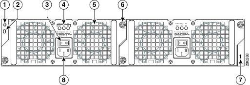
|
1 |
Chassis ESD socket |
5 |
AC power supply fan |
|
2 |
AC power supply slot number 0 |
6 |
AC power supply captive installation screw |
|
3 |
AC power supply On (|)/Off (O) switch |
7 |
AC power supply slot number 1 |
|
4 |
AC power supply LEDs |
8 |
AC power inlet |
The following imave shows the Cisco ASR 1002-X Router DC power supply.
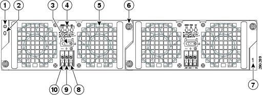
|
1 |
Chassis ESD socket |
6 |
DC power supply captive installation screw |
|
2 |
DC power supply slot 0 label |
7 |
DC power supply slot 1 label |
|
3 |
DC power supply switch Standby/On (|) |
8 |
Ground lead |
|
4 |
DC power supply LEDs |
9 |
Positive lead |
|
5 |
Power supply fan |
10 |
Negative lead |
Internal fans draw cooling air into the chassis and across internal components to maintain an acceptable operating temperature. The fans are located at the rear of the chassis. A two-hole grounding lug is located on the side of the chassis. Two power supplies, either two AC power supplies or two DC power supplies, can be accessed from the rear of the router.
 Caution |
Use only the AC power supplies or the DC power supplies in the Cisco ASR 1002-X Router. Do not mix power supply types. |
Cisco ASR 1002-X Router Slot Numbering
The Cisco ASR 1002-X Router contains an integrated SIP that supports three half-height SPAs or one half-height SPA and one full-height SPA. The SPA bays are Bay 1, Bay 2, and Bay 3. The router provides a built-in 6 Gigabit Ethernet interface, and this SPA is physically located on the integrated route processor board. The built-in 6xGE SPA ports are located in the SPA Bay 0 and addressed as GE 0/0/x.
The following image shows the Cisco ASR 1002-X Router slot numbering.

|
1 |
Built-in 6x1GE SPA in slot 0 |
4 |
SPA slot 2 |
|
2 |
SPA slot 1 |
5 |
ESP LEDs |
|
3 |
SPA slot 3 |
The Cisco ASR 1002-X Router has an integrated ESP which is not field upgradeable. Depending on the Cisco optional software license that is installed, the ESP forwarding bandwidth can be software field upgraded from the default bandwidth of 5 Gbps to 10 Gbps, 20 Gbps, or 36 Gbps. For more information about the software license, see the Cisco ASR 1000 Series Aggregation Services Routers Release Notes at: http://www.cisco.com/en/US/docs/routers/asr1000/release/notes/asr1k_rn_rel_notes.html
The following table describes the LEDs on the integrated ESP.
|
No. |
LED Label |
LED |
Color |
Behavior in the Power-Up State |
|---|---|---|---|---|
|
1 |
PWR |
Power |
Solid green |
All the power supplies are within operational limits. |
|
Off |
Off. The router is in standby mode. |
|||
|
2 |
ACTV |
Active |
Green |
The ESP is green when active. |
|
3 |
STAT |
STATUS |
Green |
Code has successfully downloaded, and is operational. |
|
Yellow |
Boot ROM has successfully loaded. |
|||
|
Red |
Not booted. |
|||
|
4 |
STBY |
Standby |
None |
Will always be off. |
Power Supplies in the Cisco ASR 1002-X Router
The Cisco ASR 1002-X Router power supply module supports the following Cisco power supplies:
-
AC power supply operates between 85 V ac to 264 V ac
-
–48 V DC power supply operates between –40.5 V dc and –72 V dc
-
+24 V DC power supply operates between 21 V dc and 36 V dc
The power supplies are installed in the rear of the chassis and are hot pluggable. The Cisco ASR 1002-X Router supports up to 588 W input power from an infrastructure standpoint (cooling capacity, midplane, and power distribution), but the initial power supply development limit is up to 470 W output (AC and DC input).
AC Power Supply for the Cisco ASR 1002-X Router
The AC power supply input inlet is an International Electrotechnical Commission (IEC) connector with an AC switch. The current rating on the connector and switch is 10 A. The AC power supply is secured into the chassis with two captive screws mounted on the faceplate.
The following table describes the AC power supply LEDs on the Cisco ASR 1002-X Router.
|
LED Label |
LED |
Color |
Description |
|---|---|---|---|
|
INPUT OK |
Power supply activity |
Green |
The AC input voltage is greater than 85V. |
|
None |
If the LED is not illuminated, then either the input voltage is less than 70V, or the power supply is turned off. If the AC input voltage is between 70V and 85V, the INPUT OK LED can be on, off, or flashing. |
||
|
FAN OK |
Power supply fan activity A bi-color LED indicates fan status. |
Green |
All fans are operational. |
|
Red |
A fan failure is detected. |
||
|
OUTPUT FAIL |
Power supply activity |
Red |
If the INPUT OK LED is illuminated, this LED is red if the DC output voltages are below the minimum limit or above the maximum limit. If the INPUT OK LED is not illuminated, this LED might be off or red. |
The following image shows the AC power supply for the Cisco ASR 1002-X Router.

|
1 |
Chassis ESD socket |
5 |
AC power supply fan |
|
2 |
AC power supply slot number 0 |
6 |
AC power supply captive installation screw |
|
3 |
AC power supply On (|) /Off (O) switch |
7 |
AC power supply slot number 1 |
|
4 |
AC power supply LEDs |
8 |
AC power supply inlet |
--48 VDC Power Supply for the Cisco ASR 1002-X Router
The –48 VDC power supply input connector is a Euro-style terminal block. It is compliant with safety agencies’ guidelines and electrical requirements of the supply. The DC power supply operates within specification from –40.5 VDC to –72 VDC continuously after the power supply DC input is turned on a threshold of –43.5 V is reached.
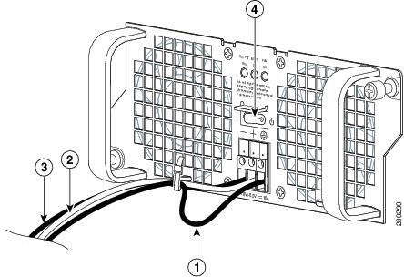
The –48 VDC power input connector accepts three wires: one positive polarity, one negative polarity, and one ground (GND) wire. There are provisions on the front panel to wire tie and strain relief the DC input wiring. The connection order is negative (–), positive (+), and GND. The DC power supply is secured into the system chassis with two captive screws mounted on the faceplate.
The following image shows the –48 VDC power supply for the Cisco ASR 1002-X Router.

|
1 |
Chassis ESD socket |
6 |
Power supply captive installation screw |
|
2 |
Power supply slot 0 label |
7 |
Power supply slot 1 label |
|
3 |
Power supply switch Standby/On (|) |
8 |
Ground lead |
|
4 |
Power supply LEDs |
9 |
Positive lead |
|
5 |
Fan |
10 |
Negative lead |
The following table lists the Cisco ASR 1002-X Router –48 VDC power supply LEDs.
|
LED Label |
LED |
Color |
Description |
|---|---|---|---|
|
INPUT OK |
A bi-color LED indicates the presence of input voltage |
Green |
The LED turns green to signal that the DC power supply input voltage is greater than 43.5VDC at turn-on and remains green until the level of 39 VDC is reached. |
|
Amber |
The LED turns amber if the power supply turns off due to low input voltage (falls below 39VDC) and indicates that a hazard (voltage on the terminal block) is still present. The LED remains amber and is active until around 20 V +/-5 V. If the input is below 15 V, the LED is not illuminated |
||
|
FAN OK |
A bi-color LED indicates power supply fan status |
Green |
The LED turns green when all fans are operational. |
|
Red |
The LED turns red when a fan failure is detected. |
||
|
OUTPUT FAIL |
Power supply activity |
Red |
When the LED is off, it signals that the DC output voltage is within the normal operating range. Output voltage between the minimum limit and maximum limit will not create an Output Fail alarm, but output voltages below the minimum limit or above the maximum limit will create an Output Fail alarm. Led turns red to indicate that the DC output is out of the specified range. When you turn on the power supply, the LED turns red for two to three seconds to test the LED operation before going off. |
The output voltage alarm is raised when the output voltage is below the low end of the minimum limit or above the high end of the maximum limit. When the output voltage is above the high end of the minimum or below the low end of the maximum limit, the red state is not activated.
The following table shows the –48 VDC power supply output voltage alarm ranges.
|
Output |
Minimum |
Maximum |
|---|---|---|
|
12 V |
10.0-11.2 V |
12.8-13.8 V |
|
3.3 V |
2.6-3.0 V |
None |
+24 VDC Power Supply for the Cisco ASR 1002-X Router
This section provides information about the +24 VDC power supply at the rear of the Cisco ASR 1002-X Router. The recommended branch circuit breaker for the Cisco ASR 1002-X Router +24 VDC power supply is a 40 A UL-listed circuit breaker.
The Cisco ASR 1002-X Router has two same-type power supplies in power supply slot 0 and power supply slot 1. The power supply slot identifiers are zero (0) on the left side of the chassis, rear side, and one (1) on the right side of the chassis, rear side. The power supply switch is a Standby switch and is not considered a disconnect.
The +24 VDC power supply uses a spring-loaded terminal block. The input terminal block requires a maximum of 8 AWG multistrand wiring to support the input current. The terminal block is compliant with safety agencies’ guidelines and the electrical requirements of the supply. Use the tie wraps to dress the input cable wires; there are two tie wrap tabs on the +24 VDC power supply. The +24 VDC power supply unit is secured into the system chassis with two captive screws mounted on the faceplate.
The following image shows the +24 VDC power supply for the Cisco ASR 1002-X Router.
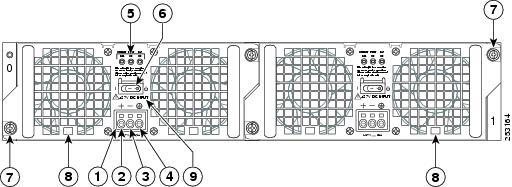
|
1 |
+24 VDC terminal block |
6 |
Standby/On switch |
|
2 |
Positive (+) lead |
7 |
Captive fastener |
|
3 |
Negative (-) lead |
8 |
Power supply tabs |
|
4 |
Ground (GND) lead |
9 |
+27 VDC INPUT label |
|
5 |
Power supply LEDs |
— |
— |
The following table shows the definitions of the Cisco ASR 1002-X Router +24 VDC power supply LEDs.
|
LED Label |
LED |
Color |
Description |
|---|---|---|---|
|
OUTPUT FAIL |
Power supply activity |
Red |
When the LED is off, it signals that the +24 VDC output voltage is within the normal operating range. Output voltage between the minimum limit and maximum limit will not create an output fail alarm, but output voltages below the minimum limit or above the maximum limit will create an Output Fail alarm. When you turn the power supply on, LED turns red for two to three seconds to test the LED operation before going off. |
|
INPUT OK |
A bicolor LED indicates the presence of input voltage |
Green |
The LED turns green to signal that voltage is > or = to 20 VDC at turn-on and the voltage reduces to 19.0VDC (+/- 0.5 V tolerance). |
|
Amber |
The LED turns to amber when the input voltage is active and is reduced to 16.0 VDC and indicates that a voltage on the terminal block is still present. The LED remains amber and is active until around 10 V. The LED should be OFF below 15.8 VDC. |
||
|
FAN OK |
A bicolor LED indicates the power supply fan status |
Green |
The LED turns to green when all fans are operational. |
|
Red |
The LED turns to red when a fan failure is detected. |
+24 VDC Power System Input for the Cisco ASR 1002-X Router
The +24 VDC power supply operates within specification between +21 VDC and +36 VDC continuously after the power supply DC input is turned on. The power supply measures the input voltage at the power supply terminals and turns off the supply when the input voltage reaches 19.0 V +/- 0.5 V when this low voltage threshold is reached, the power supply does not resume operation until the input voltage reaches 20.0 V +/- 0.5 V. When the turn-on threshold of 20 V is reached, then the +24 VDC power supply meets all specification requirements down to the low voltage threshold of 19 V (+/- tolerance).
+24 VDC Power System Output for the Cisco ASR 1002-X Router
The +24 VDC power supply output tolerance is defined in the following table, under all combinations of +24 VDC input line variation. The total system power consumption should not exceed 470 W or output rating of each power supply.
 Note |
Two power supplies are used for the redundant operation. The system’s total power consumption should not exceed the rating of one power supply to maintain redundancy. |
|
Output Voltage |
+12 VDC |
+3.3 V |
|---|---|---|
|
Minimum |
11.80 VDC |
3.20 V |
|
Nominal |
12.00 VDC |
3.30 V |
|
Maximum |
12.20 VDC |
3.40 V |
|
Output Current |
||
|
Minimum |
2.0 A |
0.10 A |
|
Maximum |
39 A |
3.125 A |
 Note |
Any combination of output voltage and current cannot exceed the total power rating of 470 W. |
The following are the important notes regarding the +24 VDC power supply in the Cisco ASR 1002-X Router:
-
Output Voltage Alarm Threshold—The Output Voltage Alarm is raised when the output voltage is below the low end of the minimum limit or above the high end of the maximum limit (as shown in the following table). When the output voltage is above the high end of the minimum limit or below the low end of the maximum limit, the LED does not turn to red.
|
Output |
Minimum |
Maximum |
|---|---|---|
|
12 V |
10.0-11.2 V |
12.8-13.8 V |
|
3.3 V |
2.6 – 3.0 V |
None |
-
Temperature—If a fan fails, the power supply meets the functional requirements specified in above table. The calculated MTBF does not apply above 55°C with less than two fans. However, all the component stress remains within the manufacturer’s specified rating.
-
Thermal shutdown—The +24 VDC power supply shuts down to protect its components due to excessive internal temperature. The +24 VDC power supply then automatically restarts after the internal temperature returns to a safe operating level.
Power Cords Supported by the Cisco ASR 1002-X Router
The following table lists the power cords that are supported by the Cisco ASR 1002-X Router.
|
Power Cord Item Number |
Description |
|---|---|
|
CAB-AC-RA |
Power Cord, 110 V, Right Angle |
|
CAB-ACA-RA |
Plug, Power Cord, Australia, 10 A, Right Angle |
|
CAB-ACB10A-RA |
Power Cord, Brazil, Right Angle, 10 A |
|
CAB-ACB16A-RA |
Power Cord, Brazil, Right Angle, 16 A |
|
CAB-ACC-RA |
Power Cord, China, Right Angle |
|
CAB-ACE-RA |
Power Cord, Europe, Right Angle |
|
CAB-ACI-RA |
Power Cord, Italy, Right Angle |
|
CAB-ACR-RA |
Power Cord, Argentina, Right Angle |
|
CAB-ACS-RA |
Power Cord, Switzerland, Right Angle |
|
CAB-ACU-RA |
Power Cord, UK, Right Angle |
|
CAB-IND-RA |
Power Cord, India, Right Angle |
|
CAB-JPN-RA |
Power Cord, Japan, Right Angle |






 Feedback