Cisco 4G Indoor Ceiling-Mount Omnidirectional Antenna (4G-ANTM-OM-CM)

This chapter contains the following:

Overview

The 4G-ANTM-OM-CM antenna is a ceiling-mount omnidirectional antenna that operates in any of the 3G or 4G bands. These bands cover the following frequencies: 700, 800, 900, 1700, 1800, 1900, 2100,and 2600 MHz.

This antenna is designed for use with Cisco 3G cellular Enhanced High-Speed WAN Interface Cards (EHWICs) and is compatible with Cisco 3G cellular products using a threaded Neill-Concelman (TNC) Male connector.

The following graphic shows a front view of the 4G-ANTM-OM-CM antenna. The green circle around the Cisco logo means that this is a 4G antenna.
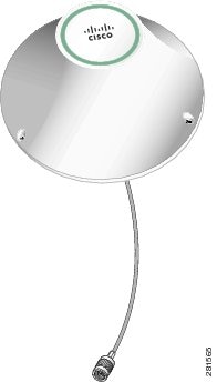
Figure 1. Cisco 4G-ANTM-OM-CM Antenna (Front View)

The following graphic shows a side view of the 4G-ANTM-OM-CM antenna.
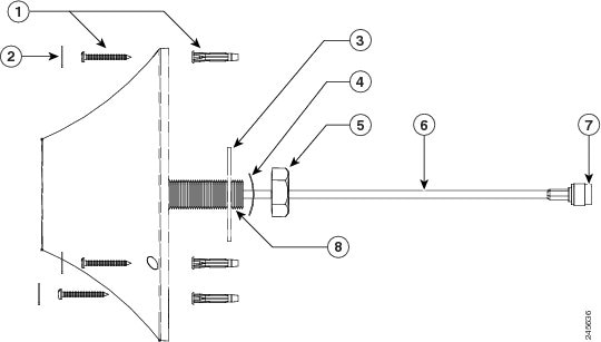
Figure 2. Cisco 4G-ANTM-OM-CM Antenna (Side View)

1

Mounting screws and anchors (#6 x 1-1/4”) for mounting on a hard ceiling

2

Self-adhesive screw covers

3

Flat washer (wide series)

4

Curved spring washer

5

Mounting nut

6

Antenna cable

7

TNC male connector

8

Thread (3/4”-16)

The following graphic shows a top view of the 4G-ANTM-OM-CM antenna.
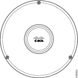
Figure 3. Cisco 4G-ANTM-OM-CM Antenna (Top View)

Technical Specifications

The following table lists the technical specifications for the 4G-ANTM-OM-CM antenna.
Antenna type

Low profile, ceiling-mount omnidirectional

Operating frequency range

698–806 MHz

824–894 MHz

925 –960 MHz

1575 MHz

1710–1885 MHz

1920–1980 MHz

2110–2170 MHz

2500–2690 MHz

Nominal Impedance

50 Ohms

Voltage Standing Wave Ratio (VSWR)

2.0:1

3.01:1 or less for GPS

Gain

700–960 MHz (1 and 1.5 dBi)

1700–2200 MHz (1.7 and 3.2 dBi)

2500–2700 MHz (3 and 4 dBi)

Radiation Pattern:

Vertical plane (-3 dB beam-width)

700–960 MHz (80 and 95 degrees)

1700 MHz (80 and 90 degrees)

1800 MHz (75 and 95 degrees)

1900 MHz (65 and 90 degrees)

2100 MHz (50 and 65 degrees)

2500–2700 MHz (50 and 65 degrees)

Azimuth plane ripple

3.5 dB over all frequencies

Efficiency

70-85% over all supported frequencies

Connector type

TNC-Male

Polarization

Linear (vertical)

Power withstanding

3 W

Weight

0.7 lb (0.34 kg)

Color

White

Flammability

UL94 V0

Environment

Indoor

Mounting

Nut, flat washer, curved spring washer, #6 x 1-1/4” mounting screws and anchors to be used for mounting to a hard ceiling, self adhesive screw covers.

Operating temperature

–22° to 158°F (–30° to 70°C)

Storage temperature

–40° to 185°F (–40° to 85°C)

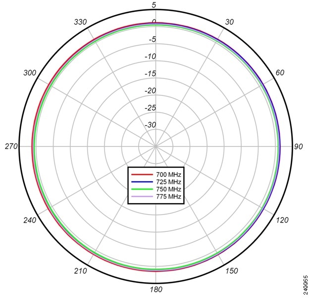
The following graphic shows the azimuth plane patterns for the 700 MHz band for the 4G-ANTM-OM-CM antenna.
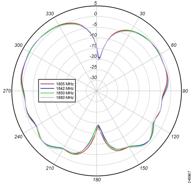
Figure 4. Azimuth Plane Patterns for the 700 MHz Band

The following graphic shows the azimuth plane patterns for the 800 MHz band for the 4G-ANTM-OM-CM antenna.

Figure 5. Azimuth Plane Patterns for the 800 MHz Band

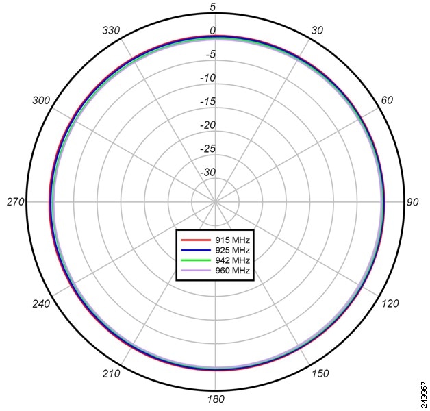
The following graphic shows the azimuth plane patterns for the 900 MHz band for the 4G-ANTM-OM-CM antenna.
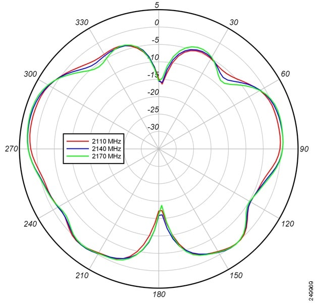
Figure 6. Azimuth Plane Patterns for the 900 MHz Band

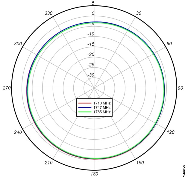
The following graphic shows the azimuth plane patterns for the 1700 MHz band for the 4G-ANTM-OM-CM antenna.
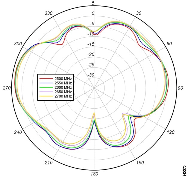
Figure 7. Azimuth Plane Patterns for the 1700 MHz Band

The following graphic shows the azimuth plane patterns for the 1800 MHz band for the 4G-ANTM-OM-CM antenna.
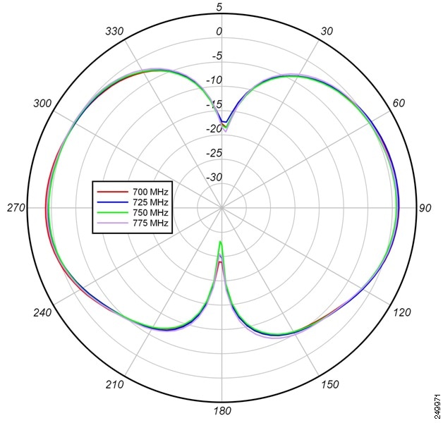
Figure 8. Azimuth Plane Patterns for the 1800 MHz Band

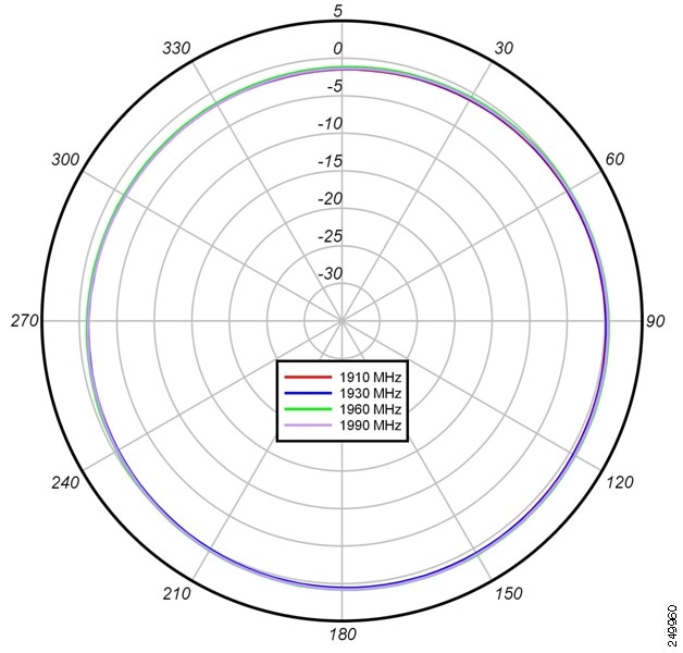
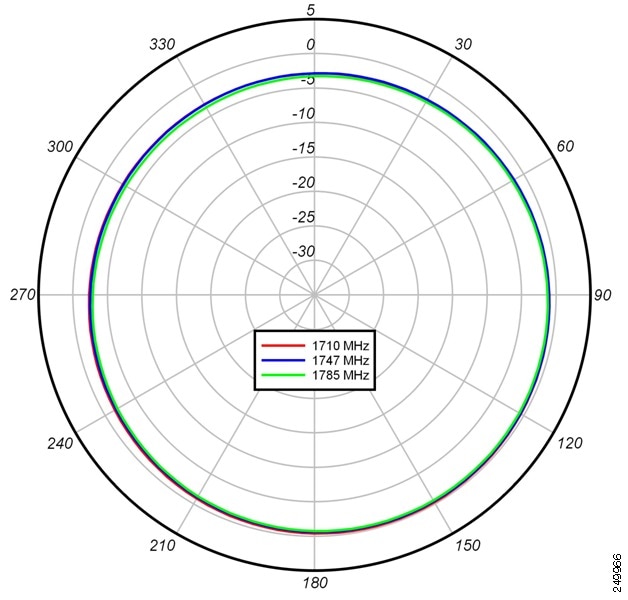
The following graphic shows the azimuth plane patterns for the 1900 MHz band for the 4G-ANTM-OM-CM antenna.
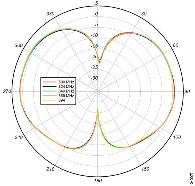
Figure 9. Azimuth Plane Patterns for the 1900 MHz Band

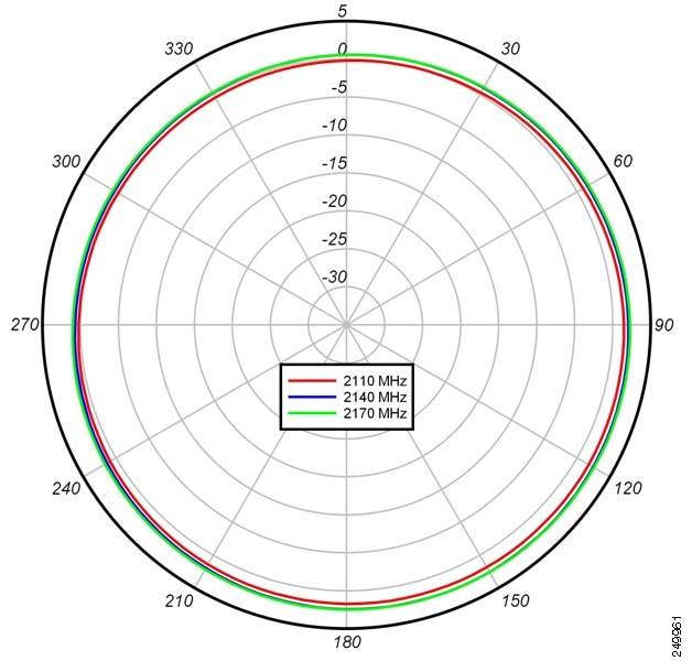
The following graphic shows the azimuth plane patterns for the 2100 MHz band for the 4G-ANTM-OM-CM antenna.

Figure 10. Azimuth Plane Patterns for the 2100 MHz Band

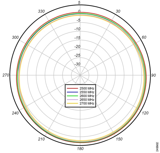
The following graphic shows the azimuth plane patterns for the 2600 MHz band for the 4G-ANTM-OM-CM antenna.
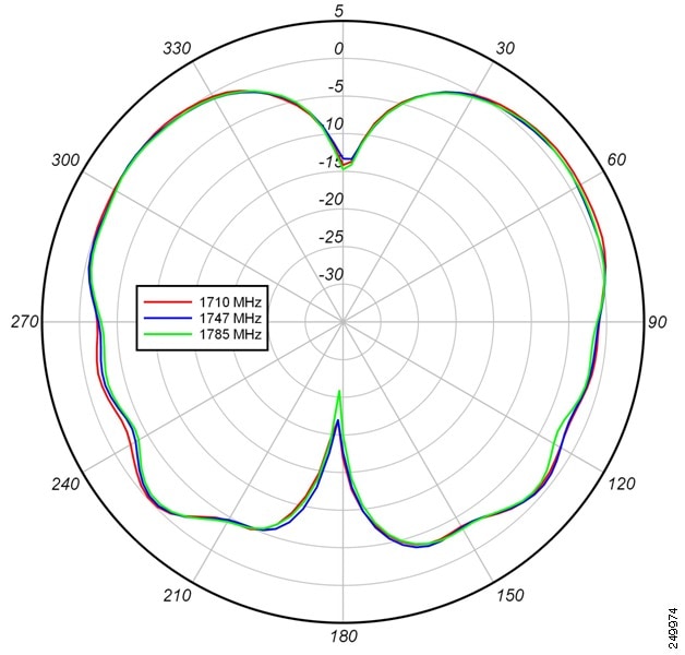
Figure 11. Azimuth Plane Patterns for the 2600 MHz Band

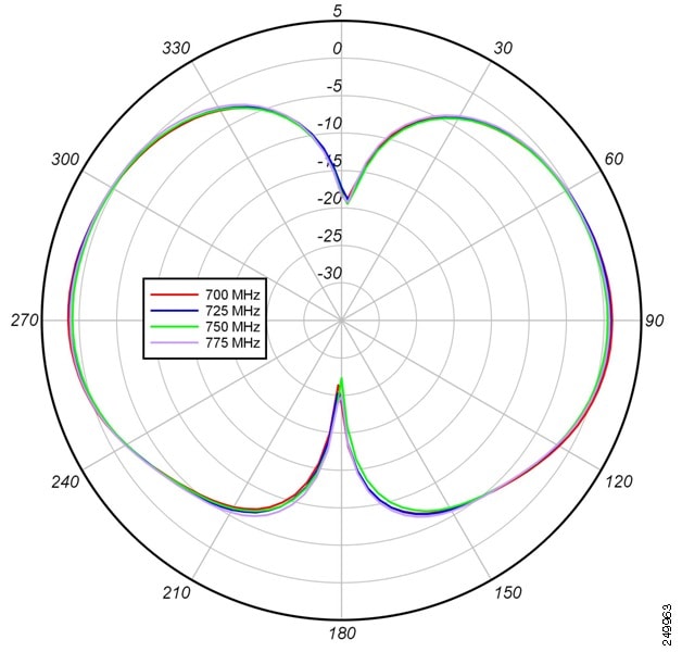
The following graphic shows the elevation plane patterns (Phi = 0 degree plane cut) for the 700 MHz band for the 4G-ANTM-OM-CM antenna.
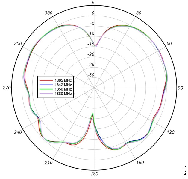
Figure 12. Elevation Plane Patterns (Phi = 0 degree Plane Cut) for the 700 MHz Band

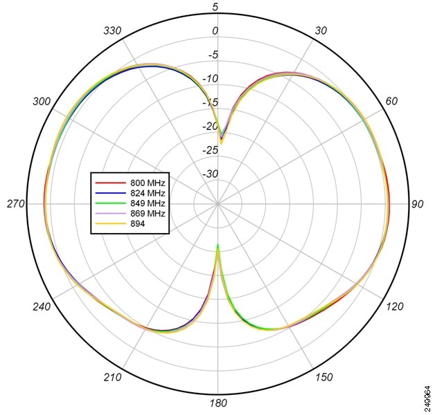
The following graphic shows the elevation plane patterns (Phi = 0 degree plane cut) for the 800 MHz band for the 4G-ANTM-OM-CM antenna.
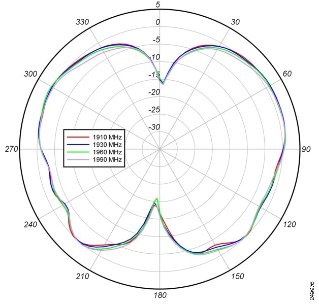
Figure 13. Elevation Plane Patterns (Phi = 0 degree Plane Cut) for the 800 MHz Band

The following graphic shows the elevation plane patterns (Phi = 0 degree plane cut) for the 900 MHz band for the 4G-ANTM-OM-CM antenna.
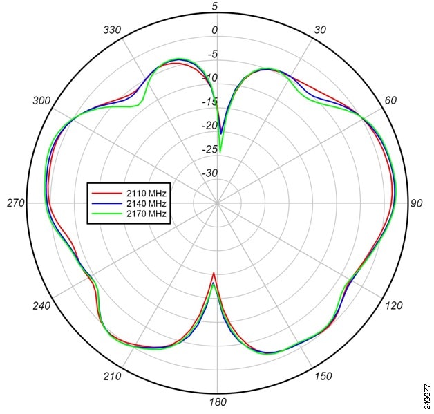
Figure 14. Elevation Plane Patterns (Phi = 0 degree Plane Cut) for the 900 MHz Band

The following graphic shows the elevation plane patterns (Phi = 0 degree plane cut) for the 1700 MHz band for the 4G-ANTM-OM-CM antenna.

Figure 15. Elevation Plane Patterns (Phi = 0 degree Plane Cut) for the 1700 MHz Band

The following graphic shows the elevation plane patterns (Phi = 0 degree plane cut) for the 1800 MHz band for the 4G-ANTM-OM-CM antenna.

Figure 16. Elevation Plane Patterns (Phi = 0 degree Plane Cut) for the 1800 MHz Band

The following graphic shows the elevation plane patterns (Phi = 0 degree plane cut) for the 1900 MHz band for the 4G-ANTM-OM-CM antenna.

Figure 17. Elevation Plane Patterns (Phi = 0 degree Plane Cut) for the 1900 MHz Band

The following graphic shows the elevation plane patterns (Phi = 0 degree plane cut) for the 2100 MHz band for the 4G-ANTM-OM-CM antenna.
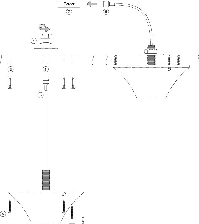
Figure 18. Elevation Plane Patterns (Phi = 0 degree Plane Cut) for the 2100 MHz Band

The following graphic shows the elevation plane patterns (Phi = 0 degree plane cut) for the 2600 MHz band for the 4G-ANTM-OM-CM antenna.

Figure 19. Elevation Plane Patterns (Phi = 0 degree Plane Cut) for the 2600 MHz Band

The following graphic shows the elevation plane patterns (Phi = 90 degree plane cut) for the 700 MHz band for the 4G-ANTM-OM-CM antenna.

Figure 20. Elevation Plane Patterns (Phi = 90 degree Plane Cut) for the 700 MHz Band

The following graphic shows the elevation plane patterns (Phi = 90 degree plane cut) for the 800 MHz band for the 4G-ANTM-OM-CM antenna.

Figure 21. Elevation Plane Patterns (Phi = 90 degree Plane Cut) for the 800 MHz Band

The following graphic shows the elevation plane patterns (Phi = 90 degree plane cut) for the 900 MHz band for the 4G-ANTM-OM-CM antenna.

Figure 22. Elevation Plane Patterns (Phi = 90 degree Plane Cut) for the 900 MHz Band

The following graphic shows the elevation plane patterns (Phi = 90 degree plane cut) for the 1700 MHz band for the 4G-ANTM-OM-CM antenna.

Figure 23. Elevation Plane Patterns (Phi = 90 degree Plane Cut) for the 1700 MHz Band

The following graphic shows the elevation plane patterns (Phi = 90 degree plane cut) for the 1800 MHz band for the 4G-ANTM-OM-CM antenna.

Figure 24. Elevation Plane Patterns (Phi = 90 degree Plane Cut) for the 1800 MHz Band

The following graphic shows the elevation plane patterns (Phi = 90 degree plane cut) for the 1900 MHz band for the 4G-ANTM-OM-CM antenna.

Figure 25. Elevation Plane Patterns (Phi = 90 degree Plane Cut) for the 1900 MHz Band

The following graphic shows the elevation plane patterns (Phi = 90 degree plane cut) for the 2100 MHz band for the 4G-ANTM-OM-CM antenna.

Figure 26. Elevation Plane Patterns (Phi = 90 degree Plane Cut) for the 2100 MHz Band

The following graphic shows the elevation plane patterns (Phi = 90 degree plane cut) for the 2600 MHz band for the 4G-ANTM-OM-CM antenna.

Figure 27. Elevation Plane Patterns (Phi = 90 degree Plane Cut) for the 2600 MHz Band

System Requirements

The 4G-ANTM-OM-CM antenna requires a Cisco 3G EHWIC that uses a TNC-Male connector.

Installation Notes

This antenna is designed to be mounted indoors on a ceiling. The antenna is mountable to ceiling tiles less than 1” thick or to hard ceilings with the included installation accessories.

Follow these guidelines to ensure the best possible performance:

The antenna must be mounted to a ceiling to maximize its omnidirectional propagation characteristics. Mounting it on a wall may noticeably decrease the antenna range and overall performance.

Wherever possible, mount the EHWIC and antenna where the wireless devices would be within sight and avoid physical obstructions. Barriers along the line of sight between antenna and EHWIC degrades the wireless radio signals.

Install the EHWIC and any antennas away from appliances that share the same frequency bands. Microwave ovens, cordless telephones, and security monitors can temporarily interfere with wireless performance.

We recommend you avoid installing wireless antennas in or near rack-mounted installations that include networking equipment and computer servers whose radiated noise emissions can severely degrade radio performance.

General Safety Precautions


Warning


This warning symbol means danger. You are in a situation that could cause bodily injury. Before you work on any equipment, be aware of the hazards involved with electrical circuitry and be familiar with standard practices for preventing accidents. Use the statement number provided at the end of each warning to locate its translation in the translated safety warnings that accompanied this device. Statement 1071

Warning


Do not work on the system or connect or disconnect cables during periods of lightning activity. Statement 1001

Warning


Do not locate the outdoor antenna near overhead power lines or other electric light or power circuits, or where it can come into contact with such circuits. When installing the antenna, take extreme care not to come into contact with such circuits, as they may cause serious injury or death. For proper installation and grounding of the antenna, please refer to national and local codes (for example, U.S.:NFPA 70, National Electrical Code, Article 810, Canada:Canadian Electrical Code, Section 54). Statement 1052

Warning


In order to comply with FCC radio frequency (RF) exposure limits, antennas should be located at a minimum of 7.9 inches (20 cm) or more from the body of all persons. Statement 332

Note


For your safety, and to help you achieve a good installation, please read and follow these safety precautions.

Mast Mounted or Building Mounted Installations

The following instructions are common to most mast mounted or building mounted installations. For specific installation instructions for each antenna, see the antenna data-sheet and the router hardware installation guide.

  • Find someone to help you—installing an antenna is often a two-person job.

  • Select your installation site with safety, as well as performance, in mind. Remember that electric power lines and phone lines look alike. For your safety, assume that any overhead line can kill you.

  • Contact your electric power company. Tell them your plans and ask them to come look at your proposed installation.

  • Do not use a metal ladder.

  • Do not work on a wet or windy day.

  • Do dress properly—wear shoes with rubber soles and heels, rubber gloves, and a long-sleeved shirt or jacket.

  • If the assembly starts to drop, move away from it and let it fall. Because the antenna, mast, cable, and metal guy wires are all excellent conductors of electrical current, even the slightest touch of any of these parts to a power line completes an electrical path through the antenna and the installer.

  • If any part of the antenna system should come in contact with a power line, do not touch it or try to remove it yourself. Call your local power company to have it removed safely.

  • If an accident should occur with the power lines, call for qualified emergency help immediately.

  • Assemble your new antenna on the ground or a level surface at the installation site.

  • Connect its coaxial cable while you are on the ground and attach the antenna to the mast.

  • Ensure that the mast does not fall as you raise or remove it. Use a durable non-conductive rope secured at each two foot level as the mast is raised. Have an assistant tend the rope, ready to pull the mast clear of any hazards (such as power lines) should it begin to fall.

  • Use the mounting bracket provided with the antenna.

  • If the installation will use guy wires:

    • Install guy anchor bolts.

    • Estimate the length of guy wire and cut it before raising the mast.

    • Attach guy wires to a mast using guy rings.

    • In the case of a guyed (tall, thin mast) installation, you must have at least one assistant to hold the mast upright while the guy wires are attached and tightened to the anchor bolts.

  • Attach a “DANGER” label at eye level on the mast.

  • Install ground rods to remove any static electricity buildup and connect a ground wire to the mast and ground rod. Use ground rods designed for that purpose, not a spare piece of pipe.

Unused Antenna Ports

Port plugs must be installed in any unused antenna ports.

The weatherproof caps on the connectors protect the router interior from environmental elements including water, heat, cold, and dust. They are installed on unused ports before the router is shipped.

When you install a new antenna in a port with an N-connector:

  • Chassis-mounted antennas—Remove the weather proof cap before installing a chassis-mounted antenna.

  • External antennas—Remove weatherproof cap, then connect the supported Cisco cable to the connector.

Installation Instructions

To install the Cisco 4G-ANTM-OM-CM antenna on a ceiling:

Procedure


Step 1

Drill a 3/4” diameter hole in the ceiling where you want to mount the antenna.

Step 2

(Optional) Drill three pilot holes and insert the supplied screw anchors.

Note

 
You can secure the antenna in place using only the mounting nut. However, for additional support, you can also use the supplied mounting screws. To use the mounting screws, you must first drill three pilot holes and insert the supplied screw anchors in place.
  1. Insert the antenna’s cable and thread through the hole you drilled in Step 1 until the base of the antenna is flush with the ceiling.

  2. Using a pencil or pen, mark the screw positions on the ceiling.

  3. Remove the antenna from the ceiling.

  4. Using a 3/16” drill bit, drill three holes for the screw anchors.

  5. Properly insert the three screw anchors into the pilot holes.

Step 3

Insert the antenna’s cable and thread through the hole you drilled in Step 1 until the base of the antenna is flush with the ceiling.

Step 4

From above the ceiling:

  1. Thread the supplied flat washer through the antenna’s cable and thread..

  2. Thread the supplied spring washer through the antenna’s cable and thread.

  3. Thread the supplied mounting nut through the antenna’s cable.

  4. Attach the mounting nut to the antenna’s thread by manually turning the nut clockwise until the antenna is secured in place.

  5. (Optional) Insert the mounting screws, then cover them with the white screw covers.

Step 5

Connect the antenna’s cable to one of the supported extension cables.

To extend the coaxial cable included with your antenna, we recommend an ultra-low-loss coaxial cable for installation flexibility without a significant loss in range. The following table lists insertion loss information about ULL extension coaxial cables available from Cisco.

Table 1.
Cisco Product Number Cable Length Frequency Range Insertion Loss
3G-CAB-ULL-20 20 foot (6 m) 500-2000 MHz –1.50 dB, maximum
3G-CAB-ULL-50 50 foot (15 m) 500-2000 MHz –3.50 dB, maximum
3G-CAB-LMR240-25 25 foot (7.5 m) 2200 MHz –3.50 dB, maximum
3G-CAB-LMR240-50 50 foot (15 m) 2200 MHz –6.90 dB, maximum
3G-CAB-LMR240-75 75 foot (23 m) 2200 MHz –10.50 dB, maximum

The callouts in the following figure correspond to the steps listed above.

Figure 28. Installation Instructions for the Cisco 4G-ANTM-OM-CM Antenna

Communications, Services, and Additional Information

  • To receive timely, relevant information from Cisco, sign up at Cisco Profile Manager.

  • To get the business impact you’re looking for with the technologies that matter, visit Cisco Services.

  • To submit a service request, visit Cisco Support.

  • To discover and browse secure, validated enterprise-class apps, products, solutions, and services, visit Cisco DevNet.

  • To obtain general networking, training, and certification titles, visit Cisco Press.

  • To find warranty information for a specific product or product family, access Cisco Warranty Finder.

Cisco Bug Search Tool

Cisco Bug Search Tool (BST) is a web-based tool that acts as a gateway to the Cisco bug tracking system that maintains a comprehensive list of defects and vulnerabilities in Cisco products and software. BST provides you with detailed defect information about your products and software.

Documentation Feedback

To provide feedback about Cisco technical documentation, use the feedback form available in the right pane of every online document.

Cisco Support Community

Cisco Support Community is a forum for you to ask and answer questions, share suggestions, and collaborate with your peers. Join the forum at https://supportforums.cisco.com/index.jspa.