Industrial Wireless 2-port High Gain Panel Antenna (IW-ANT-PNL5615-NS=)

This chapter contains the following sections:

Overview

The Industrial Wireless high gain panel antenna (IW-ANT-PNL5615-NS=) is a directional 2-port array solution deployed in a variety of applications. Its versatile mounting solutions and unique and highly efficient radiation properties make this antenna a suitable solution for point-to-point communications in the industrial wireless space.

Figure 1. Antenna Side
Figure 2. Antenna Front
Figure 3. Antenna Back
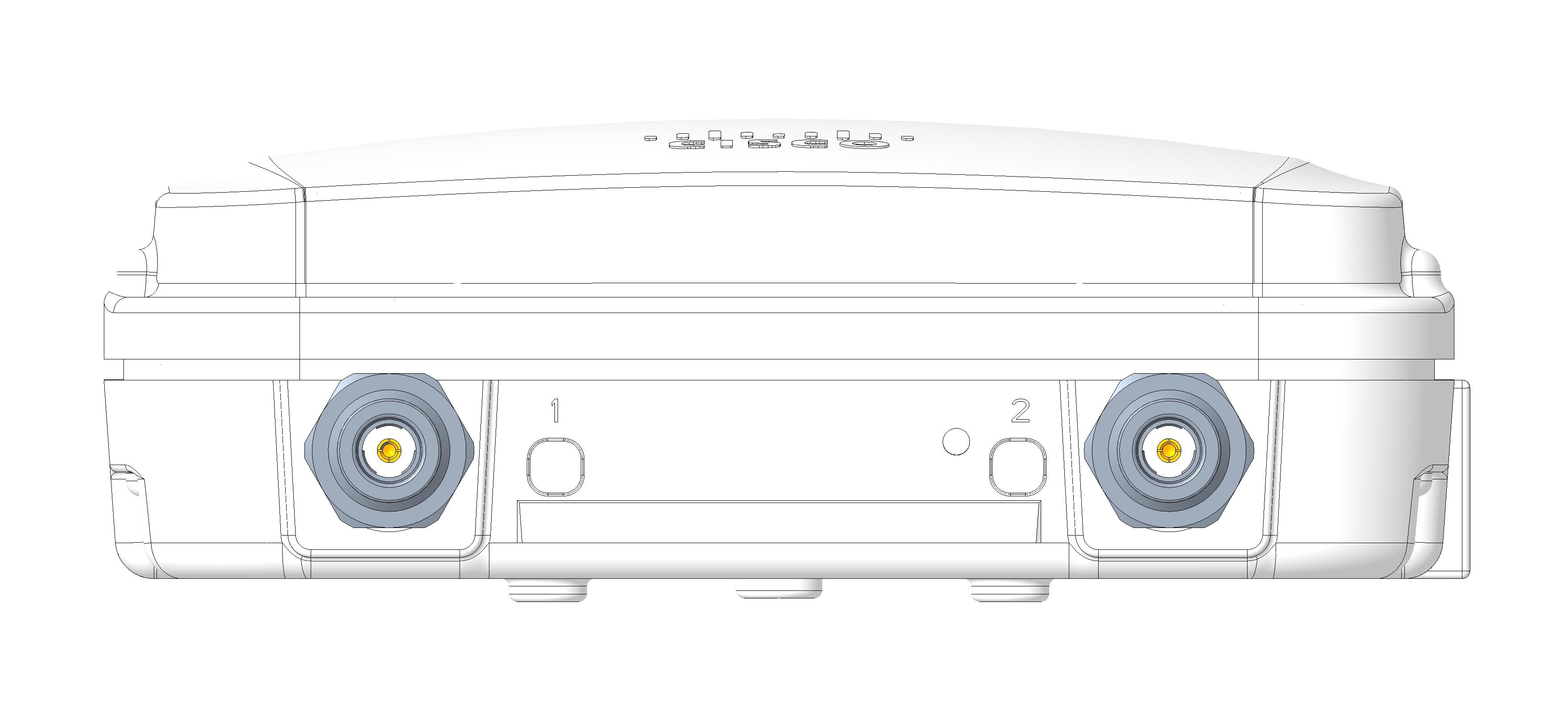
Figure 4. Antenna Bottom

Note


Port 2 contains Self-Identifying Antenna (SIA) circuitry as denoted by the dot next to the port. Connect Port 2 to the port supporting self-identification on the Access Point..

Features include the following:

  • Compact design

  • Self-Identifying Antenna (SIA) circuit

  • 15 dBi Gain

  • 2x N(f) ports

  • IP66/67 rated

  • High port-to-port isolation

Specifications

The following table lists the specifications for the antenna:

Specification

Description

Frequency

4900–5925; 5925–7125 MHz

Polarization

±45°

VSWR

< 2.2:1

Port-to-Port Isolation

> 25 dB

Maximum Gain

15 dBi

Maximum Gain above +30° Elevation

3 dBi

HPBW (V, H)

21±4 deg, 28±5 deg

Size

7.5 in x 6.9 in x 2.3 in

191.3mm x 175.3mm x 57.8mm

Wind rating

200 km/h

Operating temp

-40 to +85 °C

Flammability

UL-94 V0

IP rating

IP66, IP67

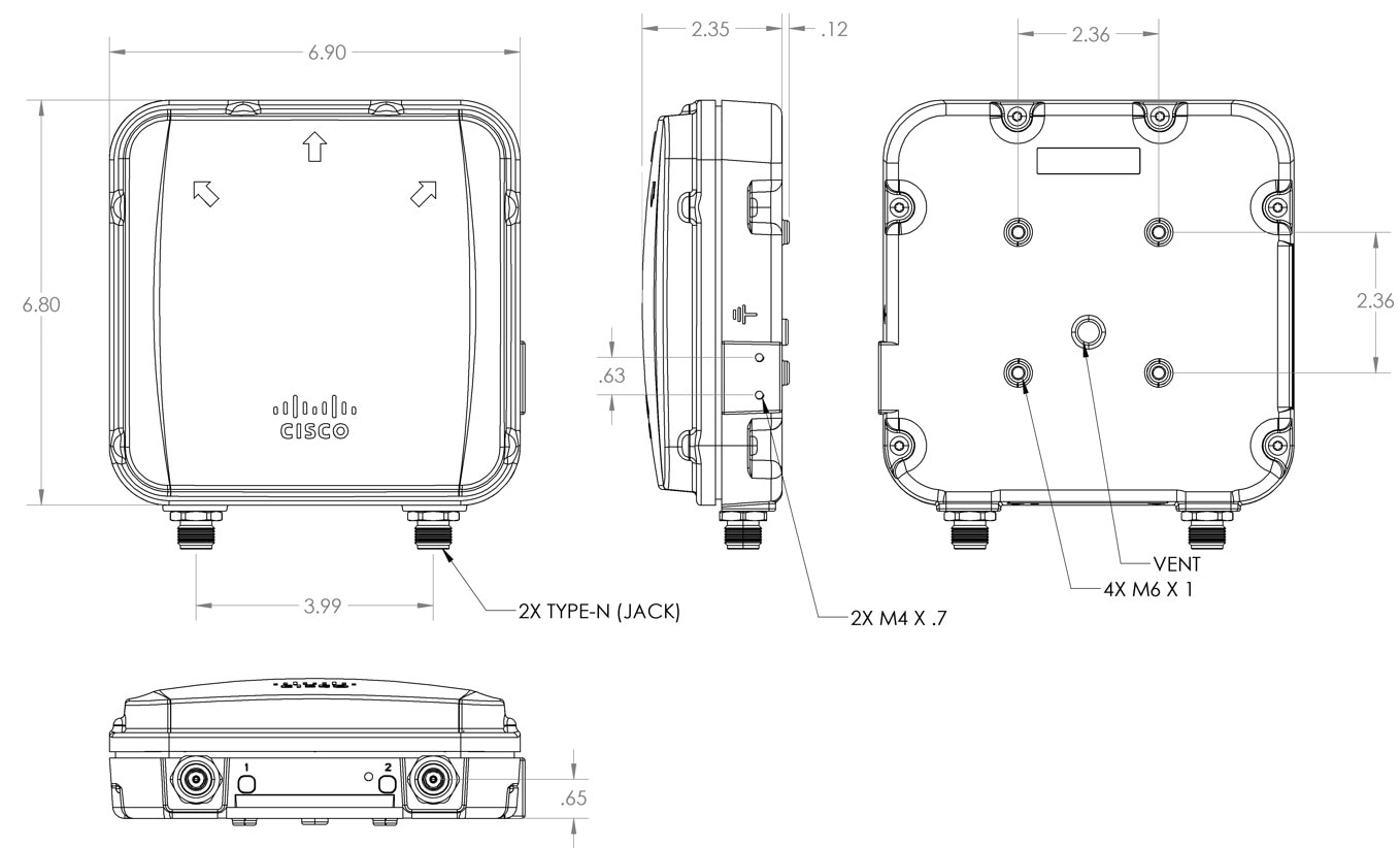
Mechanical Drawings

The following images show details about the antenna:

Radiation Charts

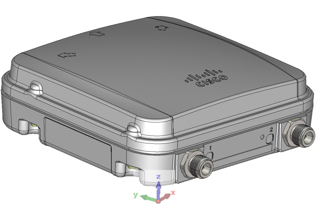
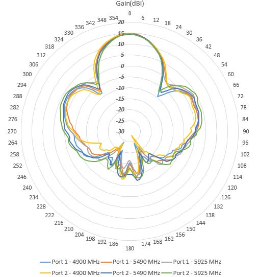
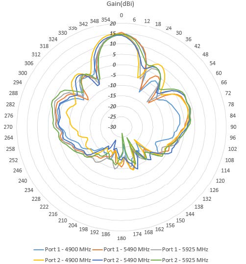
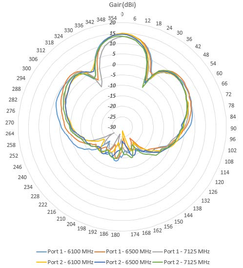
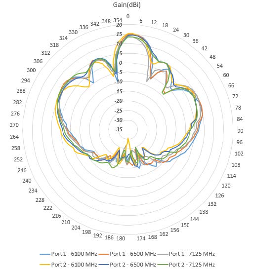
The 5–GHz and 6–GHz band radiation patterns are shown below. For illustration purposes, the reference coordinates of such polar plots are mapped to the following device orientation.

Table 1. IW-ANT-PNL5615-NS= Radiation Patterns
Figure 5. 5 GHz Radiation Pattern—Horizontal Plane (X-Z)
Figure 6. 5 GHz Radiation Pattern—Vertical Plane (Y-Z)
Figure 7. 6 GHz Radiation Pattern—Horizontal Plane (X-Z)
Figure 8. 6 GHz Radiation Pattern—Vertical Plane (Y-Z)

Installation Options

The IW-ANT-PNL5615-NS= high gain antenna can be wall or pole mounted. There are two optional mounting kits:

Cisco PID

Description

IW-ACC-PMK1=

Pole/Wall mounting bracket with tilt and rotation.

AIR-ACC1530-PMK1=

Standard Pole/Wall mount bracket

Both of these mounts are also compatible with, among others, the IW9165D access point.

To mount the antenna with the IW9165D AP, see the procedure for each mounting kit in the IW9165D Hardware Installation Guide.

Table 2. Mounting Instructions for IW9165D AP

Using the fixed mounting kit AIR-ACC1530-PMK1=

https://www.cisco.com/c/en/us/td/docs/wireless/outdoor_industrial/iw9165d/hardware/installation/b-iw9165d-hig/m-installation-overview.html#wall-mounting-the-access-point-with-the-fixed-mounting-kit

Using the tiltable mounting kit IW-ACC-PMK1=

https://www.cisco.com/c/en/us/td/docs/wireless/outdoor_industrial/iw9165d/hardware/installation/b-iw9165d-hig/m-installation-overview.html#pole-mounting-the-access-point-with-the-tiltable-mount-kit