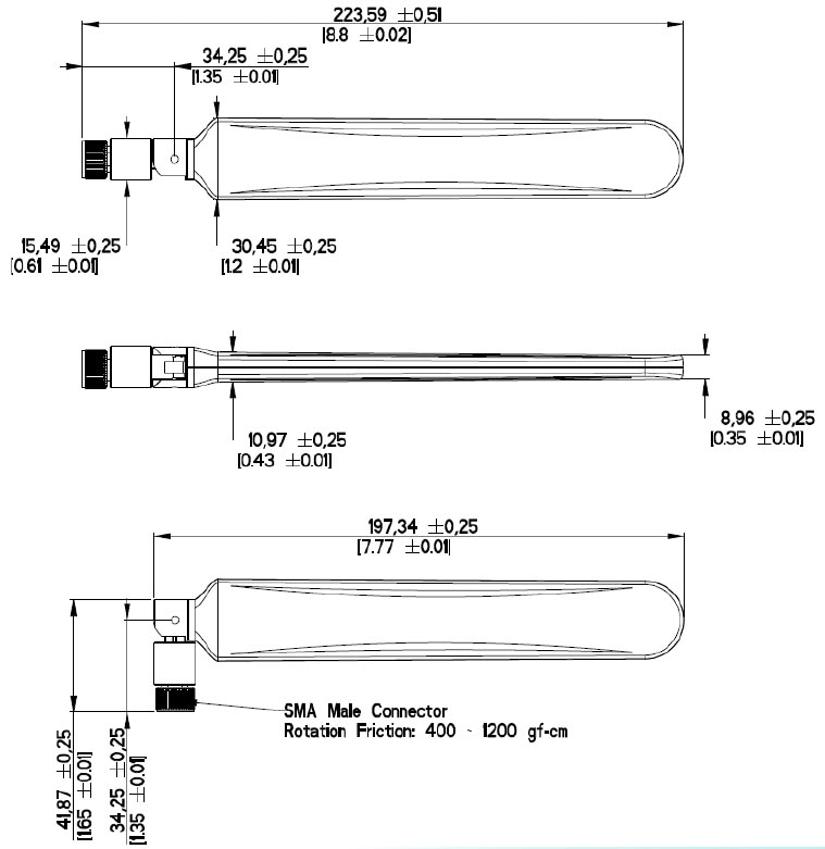
The following section contains information for installing the LTE-ANTM2-SMA-D antenna:
This antenna is designed to be mounted either directly or on an antenna extension stand to any Cisco 3G/4G wireless ISR, LTE
and LTEA router with an SMA(f) connector by threading it onto the mating connector. Refer to the routers technical documentation
for recommendations of direct mounting of antenna to the router versus installing the antenna on an antenna extension stand.
Mount and deploy the antenna at the 0° position, 45° position, or the 90° position, and then change that position at will.
The rotation of the antenna into the proper position can take place while the antenna is still loose on the mating connector.
No software is required for this installation.
In addition to the antenna orientation, the installation location of 4G routers and cellular modules play a significant role
in determining overall network performance. Routers located at the farthest coverage points might have 10 to 50 percent of
the bandwidth available compared to routers located closer to the cellular base station tower.
Because antennas transmit and receive radio signals, their performance can be adversely affected by the surrounding environment,
including physical obstructions. Radio frequency (RF) interference may occur between wireless systems located close to each
other, especially if the antennas of these systems are located close to each other.
Follow these guidelines to ensure the best possible performance:
-
When you use the antenna on a modular router with an LTE pluggable module, always mount the antenna on an appropriate extension
cable and antenna stand. The antenna performance, and therefore that of the router, will not be optimal if mounted directly
to the pluggable module.
-
Mounting of the antenna directly to smaller physical size routers is allowed.
-
For optimal performance, space multiple antennas apart by at least 17 inches (43 cm).
-
The lowest LTE frequency of 700 MHz 17 inches represents 1 wavelength. Spacing of 0.5 wavelength or 8.5 inch (22.5cm) results
in good performance.
-
Spacing of less than 8.5 inch may result in significantly reduced MIMO performance.
-
Spacing antennas close to each other (e.g. 3") results in antennas detuning from their original designed performance due to
antenna coupling.
-
Wherever possible, mount the ISR cellular router or the pluggable LTE module and antenna where the cellular base station or
tower are within sight and without physical obstructions. Barriers along the line of sight between the device and the local
base station will degrade the wireless radio signals. Install ISR cellular routers, pluggable modules and antennas above floor
level in office environments or near the ceiling for better performance because most obstructions tend to be near the floor
level.
-
The density of the materials used in a building’s construction determines the number of walls the signal must pass through
while still maintaining adequate coverage. Consider the following before choosing the location for installing your antenna:
-
Paper and vinyl walls have very little effect on signal penetration.
-
Solid and precast concrete walls limit signal penetration to one or two walls without degradation of coverage.
-
Concrete and wood block walls limit signal penetration to three or four walls.
-
A signal can penetrate five or six walls constructed of drywall or wood.
-
A thick metal wall or wire-mesh stucco wall causes signals to reflect back and causes poor penetration.
-
Avoid mounting the antenna next to a column or vertical support that could create a shadow zone and reduce the coverage area.
-
Keep the antenna away from reflective metal objects such as heating and air-conditioning ducts, large ceiling trusses, building
superstructures, and major power cabling runs. If necessary, use an extension cable to relocate the antenna away from these
obstructions.


 Feedback