W-ANTM2050D-RPSMA

Overview

This document provides the description, supported features, and installation instructions for the Cisco WLAN/Wi-Fi indoors omnidirectional dipole antenna (W-ANTM2050D-RPSMA).


Caution

Read the information in Safety Instructions before installing or replacing antennas.

The W-ANTM2050D-RPSMA omnidirectional dipole antenna is designed for indoor use with Cisco Wi-Fi 5, 6 solutions and applicable Wi-Fi input modules (WIMs) with reverse-polarity SMA (RP-SMA) connectors.

This antenna has the following features:

  • Support for frequencies of 2400-2480 MHz and 5150-5850 MHz.
  • Articulating joint that can maneuver into three stop positions: 0°, 45°, and 90°.
  • Reverse-polarity sub-miniature A connector that allows direct mounting of the antenna to applicable Cisco Wi-Fi pluggable input modules with RP-SMA connector(s)
  • The RP-SMA connector design has added rotational frictional torque to ensure the SMA interface stays properly mated, and to reduce chances of a disconnect. The design is also more finger friendly compared to a classic SMA hex nut design.
Figure 1. Cisco W-ANTM2050D-RPSMA Omnidirectional Dipole Antenna

Specifications

Table 1. Specifications of the W-ANTM2050D-RPSMA antenna

Operating Frequencies

  • 2400-2480 MHz

  • 5150-5850 MHz

Polarization

Linear, Vertical

Nominal Impedance

50 Ohms

Peak Gain

  • 2400-2480 MHz - 1.5 dBi

  • 5150-5850 MHz - 3.5 dBi

Note 
The standalone antenna peak gain numbers are provided above. When you install an antenna close to metallic objects or directly on chassis, the peak gain will be affected. We recommend that you keep antennas away from very large chassis and metallic objects. You can install antennas directly on smaller or medium size chassis. In all cases, we recommend that you keep different antennas away from each other and from various known sources of electromagnetic radiation.

VSWR

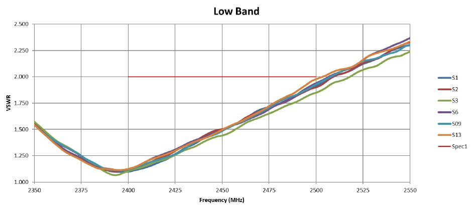
  • 2.0:1 @ 2400-2480 MHz

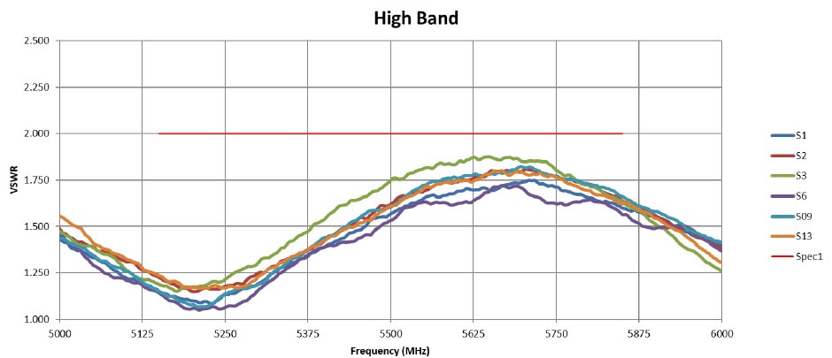
  • 2.0:1 @ 5150-5850 MHz

Power withstanding

3 W

DC Power

No DC power required for W-ANTM2050D-RPSMA antenna operation.

Dimensions

6.4” (L) x 0.83” (W) (161 x 21 mm)

Weight

33.5 grams

Average Efficiency

> 65% @ 2400MHz - 2480MH

>70% @ 5150MHz - 5850MHz

Temperature Range

-20°C to + 60°C (Operating)

-40°C to + 85°C (Storage)

Figure 2. Mechanical Drawing

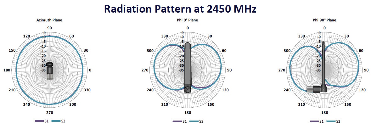
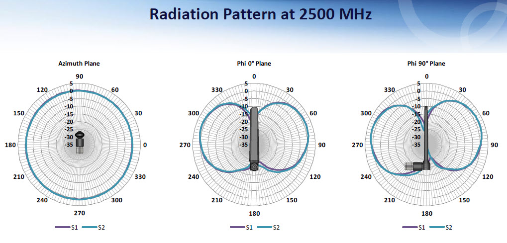
Antenna Radiation Patterns

The following graphics show the radiation patterns at different frequencies.

Antenna Impedance/VSWR

The following two graphics show the Low Band (2.4 GHz band) and High Band (5 GHz band) VSWR Performance.


Note

Said performance is measured across multiple antennas under test (AUTs).

Other Patterns

The following three graphics show the 3D Max Gain, Azimuth Plane Ripple, and the E-Plane 3dB BW.

Installation Instructions

The following section contains information for installing the W-ANTM2050D-RPSMA antenna:

This antenna is designed to be mounted either directly or on an antenna extension stand to Cisco Wi-Fi input modules (WIMs) with reverse-polarity SMA (RP-SMA) connectors by threading it onto the mating connector. Refer to the routers technical documentation for recommendations of direct mounting of antenna to the router versus installing the antenna on an antenna extension stand. Mount and deploy the antenna at the 0° position, 45° position, or the 90° position, and then change that position at will. The rotation of the antenna into the proper position can take place while the antenna is still loose on the mating connector. No software is required for this installation.

In addition to the antenna orientation, the installation location of Wi-Fi/WLAN routers and cellular modules play a significant role in determining overall network performance. Routers located at the farthest coverage points might have 10 to 50 percent of the bandwidth available compared to routers located closer to the cellular base station tower.

Because antennas transmit and receive radio signals, their performance can be adversely affected by the surrounding environment, including physical obstructions. Radio frequency (RF) interference may occur between wireless systems located close to each other, especially if the antennas of these systems are located close to each other.

Follow these guidelines to ensure the best possible performance:

  • When you use the antenna on a modular router with an LTE pluggable module, always mount the antenna on an appropriate extension cable and antenna stand. The antenna performance, and therefore that of the router, will not be optimal if mounted directly to the pluggable module.
  • Mounting of the antenna directly to smaller physical size routers is allowed.
  • For optimal performance, space multiple antennas apart by at least 17 inches (43 cm).
  • The lowest LTE frequency of 700 MHz 17 inches represents 1 wavelength. Spacing of 0.5 wavelength or 8.5 inch (22.5cm) results in good performance.
  • Spacing of less than 8.5 inch may result in significantly reduced MIMO performance.
  • Spacing antennas close to each other (e.g. 3") results in antennas detuning from their original designed performance due to antenna coupling.
  • Wherever possible, mount the ISR cellular router or the pluggable LTE module and antenna where the cellular base station or tower are within sight and without physical obstructions. Barriers along the line of sight between the device and the local base station will degrade the wireless radio signals. Install ISR cellular routers, pluggable modules and antennas above floor level in office environments or near the ceiling for better performance because most obstructions tend to be near the floor level.
  • The density of the materials used in a building’s construction determines the number of walls the signal must pass through while still maintaining adequate coverage. Consider the following before choosing the location for installing your antenna:
    • Paper and vinyl walls have very little effect on signal penetration.
    • Solid and precast concrete walls limit signal penetration to one or two walls without degradation of coverage.
    • Concrete and wood block walls limit signal penetration to three or four walls.
    • A signal can penetrate five or six walls constructed of drywall or wood.
    • A thick metal wall or wire-mesh stucco wall causes signals to reflect back and causes poor penetration.
  • Avoid mounting the antenna next to a column or vertical support that could create a shadow zone and reduce the coverage area.
  • Keep the antenna away from reflective metal objects such as heating and air-conditioning ducts, large ceiling trusses, building superstructures, and major power cabling runs. If necessary, use an extension cable to relocate the antenna away from these obstructions.

Unused Antenna Ports

Port plugs must be installed in any unused antenna ports.

The weatherproof caps on the connectors protect the router interior from environmental elements including water, heat, cold, and dust. They are installed on unused ports before the router is shipped.

When you install a new antenna in a port with an N-connector:

  • Chassis-mounted antennas—Remove the weather proof cap before installing a chassis-mounted antenna.
  • External antennas—Remove weatherproof cap, then connect the supported Cisco cable to the connector.

Communications, Services, and Additional Information

  • To receive timely, relevant information from Cisco, sign up at Cisco Profile Manager .
  • To get the business impact you’re looking for with the technologies that matter, visit Cisco Services .
  • To submit a service request, visit Cisco Support .
  • To discover and browse secure, validated enterprise-class apps, products, solutions and services, visit Cisco Marketplace .
  • To obtain general networking, training, and certification titles, visit Cisco Press .
  • To find warranty information for a specific product or product family, access Cisco Warranty Finder .

Modifications to this product not authorized by Cisco could void the FCC approval and negate your authority to operate the product.

The Cisco implementation of TCP header compression is an adaptation of a program developed by the University of California, Berkeley (UCB) as part of UCB’s public domain version of the UNIX operating system. All rights reserved. Copyright © 1981, Regents of the University of California.

NOTWITHSTANDING ANY OTHER WARRANTY HEREIN, ALL DOCUMENT FILES AND SOFTWARE OF THESE SUPPLIERS ARE PROVIDED “AS IS” WITH ALL FAULTS. CISCO AND THE ABOVE-NAMED SUPPLIERS DISCLAIM ALL WARRANTIES, EXPRESSED OR IMPLIED, INCLUDING, WITHOUT LIMITATION, THOSE OF MERCHANTABILITY, FITNESS FOR A PARTICULAR PURPOSE AND NONINFRINGEMENT OR ARISING FROM A COURSE OF DEALING, USAGE, OR TRADE PRACTICE.

IN NO EVENT SHALL CISCO OR ITS SUPPLIERS BE LIABLE FOR ANY INDIRECT, SPECIAL, CONSEQUENTIAL, OR INCIDENTAL DAMAGES, INCLUDING, WITHOUT LIMITATION, LOST PROFITS OR LOSS OR DAMAGE TO DATA ARISING OUT OF THE USE OR INABILITY TO USE THIS MANUAL, EVEN IF CISCO OR ITS SUPPLIERS HAVE BEEN ADVISED OF THE POSSIBILITY OF SUCH DAMAGES.

Any Internet Protocol (IP) addresses and phone numbers used in this document are not intended to be actual addresses and phone numbers. Any examples, command display output, network topology diagrams, and other figures included in the document are shown for illustrative purposes only. Any use of actual IP addresses or phone numbers in illustrative content is unintentional and coincidental.

All printed copies and duplicate soft copies of this document are considered uncontrolled. See the current online version for the latest version.

Cisco has more than 200 offices worldwide. Addresses, phone numbers, and fax numbers are listed on the Cisco website at www.cisco.com/go/offices .

© 2015-2021 Cisco Systems, Inc. All rights reserved.