Overview
This section provides the description, supported features, and installation instructions of the Cisco Dual LTE-Single GPS Multi-band (4G-LTE-ANTM-O-3-B) Antenna.
 Caution |
Read the information in the installation instructions before installing or replacing antennas. |
Deciding which antenna to use involves multiple factors, such as coverage area, maximum distance, indoor location, outdoor location, and antenna height.
When an antenna is used indoors, the building construction, ceiling height, and internal obstructions must be considered. In outdoor environments, obstructions such as trees, vehicles, buildings, and hills must be considered. Distance is the primary factor when using outdoor-wireless communications. However, coverage area also becomes important when you use wireless client devices to communicate with a wireless device.
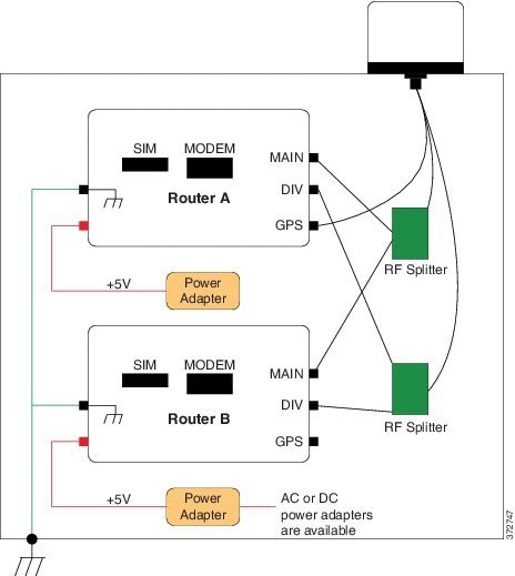
4G-LTE-ANTM-O-3-B antenna is an integrated 3-in-1- indoor and outdoor antenna. It comes with two Long Term Evolution (LTE) antennas and one Global Positioning System (GPS) antenna in a single radome. The following graphic shows the 4G-LTE-ANTM-O-3 antenna.

Parts List
The shipment of your antenna includes the following items:
- One Antenna Unit
- Two SMA-Female to TNC-Male Adapters
- Installation Guide
Features of the 4G-LTE-ANTM-O-3-B Antenna
The 4G-LTE-ANTM-O-3-B antenna supports the following features:
- No tune, multiband coverage, dual 4G LTE, and GPS L1 frequencies.
- Metal 5/8-inch stud mount with serrated face nut provides single cable exit for easier installation or antenna replacement.
- Attractive low-profile housing for added overhead clearance.
- IP67-compliant design provides maximum protection against water or dust under severe environmental conditions.
- High-performance, low-loss cable, and high-quality connectors for maximum Radio Frequency (RF) system efficiency.
- UV-resistant red, blue, black, or white radome.
Technical Specifications
The following table lists the specifications for the RF antenna.
|
Operating Frequencies |
698-960 MHz 1710-2700 MHz |
|
Polarization |
Vertical, linear |
|
Nominal Impedance |
50 Ohms |
|
Gain (Typical) Note 1 |
2.5 dBi |
|
Maximum Power |
3 Watts |
|
VSWR Note 2 |
< 2.5:1 |
|
Elevation Plane (3 dB Beamwidth) |
30° (nominal) |
|
Azimuth Plane (3 dB Beamwidth) |
Omni-directional |
|
Connector type |
SMA-Male |
|
Cable |
4 foot RG174 VW-1 compliant |
|
Height |
90 mm |
|
Base Diameter |
137 mm |
|
Color |
White, Black, Red or Blue |
|
Flammability |
UL-94 V0 |
|
Environment |
Indoor and outdoor |
|
Mounting |
5/8 inch lug with serrated face nut, optional adhesive backing (peel-off), 17 sq. inches area (minimum) on a flat smooth surface, 5/8 inch diameter hole through mounting surface |
|
Operating and storage temperature |
-40 to +85 degree C |
|
Ingress Protection Note 3 |
IP67 |
Note 1: Total gain, free space test when mounted on a 1-foot diameter ground plane with unused ports loaded.
Note 2: Free space Voltage Standing Wave Ratio (VSWR) over all operating frequency ranges when mounted on a 1-foot diameter ground plane with unused ports loaded.
Note 3: When mounted per installation instructions.
The following table lists the specifications for the GPS Antenna.
|
Frequency Band |
1575.42 MHz (GPS L1) |
|
Amplifier Gain |
26 dBc ± 3 dB |
|
Nominal Impedance |
50 Ohms |
|
Output VSWR |
1.5:1 typical |
|
DC Current |
20 mA nominal; < 30 mA @ -40°C to +85° C |
|
DC Voltage |
3.3-5 V |
|
Noise Figure |
1.8 dB typical |
|
Filtering |
> 40 dB rejection @ ± 50 MHz from center frequency |
The following graphic shows the parts of 4G-LTE-ANTM-O-3-B Antenna.

|
1 |
GPS and 2 LTE antennas inside |
4 |
Mounting stud |
|
2 |
Radome available in 4 colors: White, Black, Red or Blue (Indoor or Outdoor) |
5 |
Cables |
|
3 |
Gasket |
The following graphic shows the antenna with cable labels.

|
1 |
MPN LABEL |
2 |
LTE-ID LABEL 2EA |
|
3 |
GPS ID LABEL |
The following figure shows the Low Band 698-960 MHz EL (PHI=0).

The following figure shows the Low Band 698-960 MHz EL (PHI=90).

The following figure shows the Low Band 698-960 MHz AZ (THETA=90).

The following figure shows High Band 1710-2700 MHz EL (PHI=0).

The following figure shows High Band 1710-2700 MHz EL (PHI=90).

The following figure shows High Band 1710-2700 MHz AZ (THETA=90).


 Feedback