Basic Interface Configuration for Firepower 1010 and Secure Firewall 1210/1220 Switch Ports

You can configure each Firepower 1010 or Secure Firewall 1210/1220 interface to run as a regular firewall interface or as a Layer 2 hardware switch port. This chapter includes tasks for starting your switch port configuration, including enabling or disabling the switch mode and creating VLAN interfaces and assigning them to switch ports. This chapter also describes how to customize Power over Ethernet (PoE) on supported interfaces.

About Firepower 1010 and Secure Firewall 1210/1220 Switch Ports

This section describes the switch ports of the Firepower 1010 and Secure Firewall 1210/1220.

Understanding Switch Ports and Interfaces

Ports and Interfaces

For each physical Firepower 1010 or Secure Firewall 1210/1220 interface, you can set its operation as a firewall interface or as a switch port. See the following information about physical interface and port types as well as logical VLAN interfaces to which you assign switch ports:

  • Physical firewall interface—In routed mode, these interfaces forward traffic between networks at Layer 3, using the configured security policy to apply firewall and VPN services. In transparent mode, these interfaces are bridge group members that forward traffic between the interfaces on the same network at Layer 2, using the configured security policy to apply firewall services. In routed mode, you can also use Integrated Routing and Bridging with some interfaces as bridge group members and others as Layer 3 interfaces. By default, the Ethernet 1/1 interface is configured as a firewall interface.

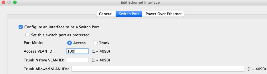
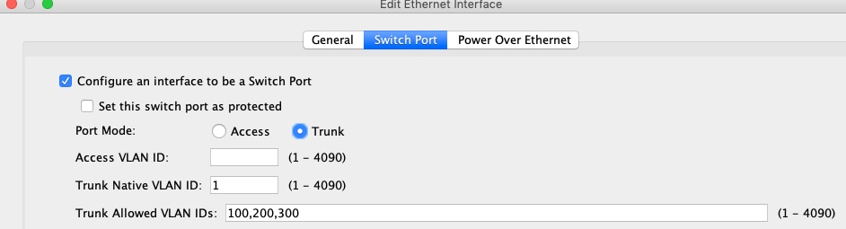
  • Physical switch port—Switch ports forward traffic at Layer 2, using the switching function in hardware. Switch ports on the same VLAN can communicate with each other using hardware switching, and traffic is not subject to the ASA security policy. Access ports accept only untagged traffic, and you can assign them to a single VLAN. Trunk ports accept untagged and tagged traffic, and can belong to more than one VLAN. By default, Ethernet 1/2 through 1/8 (1010 and 1210) or Ethernet 1/2 through 1/10 (1220) are configured as access switch ports on VLAN 1. You cannot configure the Management interface as a switch port.

  • Logical VLAN interface—These interfaces operate the same as physical firewall interfaces, with the exception being that you cannot create subinterfaces, or EtherChannel interfaces. When a switch port needs to communicate with another network, then the ASA device applies the security policy to the VLAN interface and routes to another logical VLAN interface or firewall interface. You can even use Integrated Routing and Bridging with VLAN interfaces as bridge group members. Traffic between switch ports on the same VLAN are not subject to the ASA security policy, but traffic between VLANs in a bridge group are subject to the security policy, so you may choose to layer bridge groups and switch ports to enforce the security policy between certain segments.
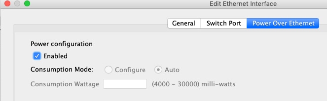
Power Over Ethernet

Power over Ethernet+ (PoE+) is supported on Ethernet 1/7 and Ethernet 1/8 on the Firepower 1010.

Auto-MDI/MDIX Feature

For all switch ports, the default auto-negotiation setting also includes the Auto-MDI/MDIX feature. Auto-MDI/MDIX eliminates the need for crossover cabling by performing an internal crossover when a straight cable is detected during the auto-negotiation phase. Either the speed or duplex must be set to auto-negotiate to enable Auto-MDI/MDIX for the interface. If you explicitly set both the speed and duplex to a fixed value, thus disabling auto-negotiation for both settings, then Auto-MDI/MDIX is also disabled. When the speed and duplex are set to 1000 and full, then the interface always auto-negotiates; therefore Auto-MDI/MDIX is always enabled and you cannot disable it.

Guidelines and Limitations for Switch Ports

Context Mode

The Firepower 1010 and Secure Firewall 1210/1220 does not support multiple context mode.

Failover and Clustering

  • No cluster support.

  • Active/Standby failover support only.

  • You should not use the switch port functionality when using Failover. Because the switch ports operate in hardware, they continue to pass traffic on both the active and the standby units. Failover is designed to prevent traffic from passing through the standby unit, but this feature does not extend to switch ports. In a normal Failover network setup, active switch ports on both units will lead to network loops. We suggest that you use external switches for any switching capability. Note that VLAN interfaces can be monitored by failover, while switch ports cannot. Theoretically, you can put a single switch port on a VLAN and successfully use Failover, but a simpler setup is to use physical firewall interfaces instead.

  • You can only use a firewall interface as the failover link.

Logical VLAN Interfaces

  • You can create up to 60 VLAN interfaces.

  • If you also use VLAN subinterfaces on a firewall interface, you cannot use the same VLAN ID as for a logical VLAN interface.

  • MAC Addresses:

    • Routed firewall mode—All VLAN interfaces share a MAC address. Ensure that any connected switches can support this scenario. If the connected switches require unique MAC addresses, you can manually assign MAC addresses. See Configure the Manual MAC Address, MTU, and TCP MSS.

    • Transparent firewall mode—Each VLAN interface has a unique MAC address. You can override the generated MAC addresses if desired by manually assigning MAC addresses. See Configure the Manual MAC Address, MTU, and TCP MSS.

Bridge Groups

You cannot mix logical VLAN interfaces and physical firewall interfaces in the same bridge group.

VLAN Interface and Switch Port Unsupported Features

VLAN interfaces and switch ports do not support:

  • Dynamic routing

  • Multicast routing

  • Policy based routing

  • Equal-Cost Multi-Path routing (ECMP)

  • VXLAN

  • EtherChannels

  • Failover and state link

  • Traffic zones

  • Security group tagging (SGT)

Other Guidelines and Limitations

  • You can configure a maximum of 60 named interfaces on the Firepower 1010 and Secure Firewall 1210/1220.

  • You cannot configure the Management interface as a switch port.

Default Settings

  • Ethernet 1/1 is a firewall interface.

  • On Firepower 1010 and Secure Firewall 1210, Ethernet 1/2 through Ethernet 1/8 are switch ports assigned to VLAN 1.

  • On Secure Firewall 1220, Ethernet 1/2 through Ethernet 1/10 are switch ports assigned to VLAN 1.

  • Default Speed and Duplex—By default, the speed and duplex are set to auto-negotiate.

Configure Switch Ports and Power Over Ethernet

To configure switch ports and PoE, complete the following tasks.

Configure a VLAN Interface

This section describes how to configure VLAN interfaces for use with associated switch ports.

Procedure


Step 1

Choose Configuration > Device Setup > Interface Settings > Interfaces, and choose Add > VLAN Interface.

Step 2

In the VLAN ID field, enter the VLAN ID for this interface, between 1 and 4070, excluding IDs in the range 3968 to 4047, which are reserved for internal use.

Step 3

(Optional) In the Block Traffic From this Interface to drop-down list, choose the VLAN to which this VLAN interface cannot initiate traffic.

For example, you have one VLAN assigned to the outside for internet access, one VLAN assigned to an inside business network, and a third VLAN assigned to your home network. The home network does not need to access the business network, so you can use the Block Traffic From this Interface to option on the home VLAN; the business network can access the home network, but the home network cannot access the business network.

Step 4

Click OK.

Step 5

Click Apply.


Configure Switch Ports as Access Ports

To assign a switch port to a single VLAN, configure it as an access port. Access ports accept only untagged traffic. By default, Ethernet 1/2 through Ethernet 1/8 switch ports are enabled and assigned to VLAN 1 on Firepower 1010 and Secure Firewall 1210. On the Secure Firewall 1220, by default, Ethernet 1/2 through Ethernet 1/10 switch ports are enabled and assigned to VLAN 1.


Note


The device does not support Spanning Tree Protocol for loop detection in the network. Therefore you must ensure that any connection with the ASA does not end up in a network loop.


Procedure


Step 1

Choose Configuration > Device Setup > Interface Settings > Interfaces, select the interface you want to edit, and click Edit.

Step 2

Click Switch Port.

Step 3

Check the Configure an interface to be a Switch Port check box.

Step 4

(Optional) Check the Set this switch port as protected check box to prevent the switch port from communicating with other protected switch ports on the same VLAN.

You might want to prevent switch ports from communicating with each other if: the devices on those switch ports are primarily accessed from other VLANs; you do not need to allow intra-VLAN access; and you want to isolate the devices from each other in case of infection or other security breach. For example, if you have a DMZ that hosts three web servers, you can isolate the web servers from each other if you apply the Set this switch port as protected option to each switch port. The inside and outside networks can both communicate with all three web servers, and vice versa, but the web servers cannot communicate with each other.

Step 5

For the Port Mode, click the Access radio button.

Step 6

Enter the Access VLAN ID associated with this switch port, between 1 and 4070.

The default is VLAN 1.

Step 7

Click General.

Step 8

Check Enable Interface.

Note


Other fields on the General page, such as the Interface Name, are not applicable to switch ports.

Step 9

(Optional) Set hardware properties.

  1. Click Configure Hardware Properties.

  2. Choose the Duplex.

    The default is Auto.

  3. Choose the Speed.

    The default is Auto.

  4. Click OK.

Step 10

Click OK.

Step 11

Click Apply.


Configure Switch Ports as Trunk Ports

This procedure describes how to create a trunk port that can carry multiple VLANs using 802.1Q tagging. Trunk ports accept untagged and tagged traffic. Traffic on allowed VLANs pass through the trunk port unchanged.

When the trunk receives untagged traffic, it tags it to the native VLAN ID so that the ASA can forward the traffic to the correct switch ports, or can route it to another firewall interface. When the ASA sends native VLAN ID traffic out of the trunk port, it removes the VLAN tag. Be sure to set the same native VLAN on the trunk port on the other switch so that the untagged traffic will be tagged to the same VLAN.

Procedure


Step 1

Choose Configuration > Device Setup > Interface Settings > Interfaces, select the interface you want to edit, and click Edit.

Step 2

Click Switch Port.

Step 3

Check the Configure an interface to be a Switch Port check box.

Step 4

(Optional) Check the Set this switch port as protected check box to prevent the switch port from communicating with other protected switch ports on the same VLAN.

You might want to prevent switch ports from communicating with each other if: the devices on those switch ports are primarily accessed from other VLANs; you do not need to allow intra-VLAN access; and you want to isolate the devices from each other in case of infection or other security breach. For example, if you have a DMZ that hosts three web servers, you can isolate the web servers from each other if you apply the Set this switch port as protected option to each switch port. The inside and outside networks can both communicate with all three web servers, and vice versa, but the web servers cannot communicate with each other.

Step 5

For the Port Mode, click the Trunk radio button.

Step 6

Enter the Trunk Native VLAN ID, between 1 and 4070. The default is VLAN 1.

Each port can only have one native VLAN, but every port can have either the same or a different native VLAN.

Step 7

Enter the Trunk Allowed VLAN IDs associated with this switch port, separated by commas, between 1 and 4070.

If you include the native VLAN in this field, it is ignored; the trunk port always removes the VLAN tagging when sending native VLAN traffic out of the port. Moreover, it will not receive traffic that still has native VLAN tagging.

Step 8

Click General.

Step 9

Check Enable Interface.

Note


Other fields on the General page, such as the Interface Name, are not applicable to switch ports.

Step 10

(Optional) Set hardware properties.

  1. Click Configure Hardware Properties.

  2. Choose the Duplex.

    The default is Auto.

  3. Choose the Speed.

    The default is Auto.

  4. Click OK.

Step 11

Click OK.

Step 12

Click Apply.


Configure Power Over Ethernet

On Firepower 1010, Ethernet 1/7 and Ethernet 1/8 support Power over Ethernet (PoE) for devices such as IP phones or wireless access points. On Secure Firewall 1210CP, Ethernet 1/5-1/8 support PoE.The Firepower 1010 and Secure Firewall 1210CP supports both IEEE 802.3af (PoE) and 802.3at (PoE+). PoE+ uses Link Layer Discovery Protocol (LLDP) to negotiate the power level. PoE+ can deliver up to 30 watts to a powered device. Power is only supplied when needed.

If you shut down the interface, then you disable power to the device.

On Firepower 1010, PoE is enabled by default on Ethernet 1/7 and Ethernet 1/8. On Secure Firewall 1210CP, PoE is enabled by default on Ethernet 1/5-1/8. This procedure describes how to disable and enable PoE and how to set optional parameters.

Procedure


Step 1

Choose Configuration > Device Setup > Interface Settings > Interfaces, select the interface you want to edit (either Ethernet 1/7 or 1/8 on Firepower 1010, or any interface from Ethernet 1/5-1/8 on Secure Firewall 1210CP), and click Edit.

Step 2

Click Power Over Ethernet.

Step 3

Check Enabled.

Step 4

Click the Consumption Mode: Configure or Auto radio button.

  • Auto—Delivers power automatically to the powered device using a wattage appropriate to the class of the powered device. The Firepower 1010 and Secure Firewall 1210CP uses LLDP to further negotiate the correct wattage.

  • Configure—Manually specifies the wattage in milliwatts in the Consumption Wattage field, from 4000 to 30000. Use this option if you want to set the watts manually and disable LLDP negotiation.

Step 5

Click OK.

Step 6

Click Apply.

Step 7

Choose Monitor > Interfaces > Power Over Ethernet to view the current PoE+ status.


Monitoring Switch Ports

  • Monitoring > Interfaces > ARP Table

    Displays the ARP table, including static and dynamic entries. The ARP table includes entries that map a MAC address to an IP address for a given interface.

  • Monitoring > Interfaces > MAC Address Table

    Shows the static and dynamic MAC address entries.

  • Monitoring > Interfaces > Interface Graphs

    Shows interface statistics in graph or table form.

  • Monitoring > Interfaces > L2 Switching

    Shows the VLAN–to–switch port association and the static and dynamic MAC address entries.

  • Monitoring > Interfaces > Power Over Ethernet

    Shows the PoE+ status.

History for Switch Ports

Table 1. History for Switch Ports

Feature Name

Version

Feature Information

Secure Firewall 1210/1220 hardware switch support

9.22(1)

The Secure Firewall 1210/1220 supports setting each Ethernet interface to be a switch port or a firewall interface.

Secure Firewall 1210CP PoE+ support on Ethernet ports 1/5-1/8

9.22(1)

The Secure Firewall 1210CP supports Power over Ethernet+ (PoE+) on Ethernet ports 1/5-1/8.

Firepower 1010 hardware switch support

9.13(1)

The Firepower 1010 supports setting each Ethernet interface to be a switch port or a firewall interface.

New/Modified screens:

  • Configuration > Device Setup > Interface Settings > Interfaces > Edit > Switch Port

  • Configuration > Device Setup > Interface Settings > Interfaces > Add VLAN Interface

  • Monitoring > Interfaces > L2 Switching

Firepower 1010 PoE+ support on Ethernet 1/7 and Ethernet 1/8

9.13(1)

The Firepower 1010 supports Power over Ethernet+ (PoE+) on Ethernet 1/7 and Ethernet 1/8.

New/Modified screens:

  • Configuration > Device Setup > Interface Settings > Interfaces > Edit > Power Over Ethernet

  • Monitoring > Interfaces > Power Over Ethernet